Lionel SC-2 User manual

Lionel SC-2 Switch and
Accessory Controller
Owner’s Manual
CAUTION-ELECTRIC TOY NOT RECOMMENDED FOR CHILDREN UNDER EIGHT
YEARS OF AGE. AS WITH ALL ELECTRIC PRODUCTS, PRECAUTIONS SHOULD
BE OBSERVED DURING HANDLING AND USE TO PREVENT ELECTRIC SHOCK.
TRANSFORMER RATING-INPUT:120VAC;60 HZ ONLY;AC OUTPUT:12 VAC;3.6VA.
72-2980-250
2/07

2
Congratulations
Congratulations on your purchase of the
Lionel TrainMaster SC-2 Switch and
Accessory Controller! With this device you
can experience the benefits of TrainMaster
Command Control when operating your
switches and accessories with your CAB-1
Remote Controller.
The SC-2 listens for and responds to
switch (SW), route (RTE), and accessory
(ACC) commands from your CAB-1 Remote
Controller and Command Base.
You may choose to operate your SC-2 in its
standard configuration or in either of the two
alternate modes. The standard configuration
controls four switches and four accessories.
When operating in the alternate modes, you
may control up to six switches, or twelve acces-
sory actions.
A CAB-1 Remote Control (6-12868) and a Command Base (6-12911) are required
to operate the SC-2. Find them both at your authorized Lionel dealer.
Note!
The following Lionel marks may be used throughout this instruction manual and are protected under
law. All rights reserved.
Lionel®, TrainMaster®, Odyssey®, RailSounds™, CrewTalk™, TowerCom™, DynaChuff™,
StationSounds™, Pullmor®, ElectroCoupler™, Magne-Traction®, CAB-1 Remote Controller®,
PowerMaster®, Lionel ZW®, ZW®, PowerHouse®, TMCC™, Lionelville™

3
Table of contents
Installing the SC-2 on your railroad
SC-2 basics 4-5
Powering your SC-2 6-7
Connecting Lionel switches to the SC-2 8-9
Modifying O-27 switches for use with the SC-2 10
Connecting hi-rail switch motors to SC-2 11-12
Operating switches with your SC-2
Programming the SC-2 switch numbers 13
Controlling switches with CAB-1 14
Creating routes around your railroad 15-16
Activating routes 17
Modifying routes 17
Clearing Routes 18
Operating accessories with your SC-2
Connecting accessories to the SC-2 19
Programming SC-2 accessory ID#’s 20
Controlling accessories with your CAB-1 21
Advancd opertions
Operating switches only 22
Operating accessories only 23
Operating output terminal connections 24
Troubleshooting
Replacing the fuse 25
Answers to questions 26-27
Accessory connections
Rotary beacon/Control tower/Floodlight tower/Icing station 28
Water tower 28
Lumber mill/Sawmill 29
Switch tower 29
Diesel fueling station 30
Oil derrick 30
Lumber loader 31
Log loader 31
Coal tower 32
Whistle shack 32
Freight station 33
Aircraft pylon 33
Oil drum loader 34
Bascule bridge 34
Uncoupling track 35
Lionel Service 36

4
Each SC-2 can control switches and acces-
sories through commands from the
CAB-1 Remote Controller and Command Base.
All SC-2 outputs are rated for 15 amps and
can control most switches and accessories
directly. Use the sheet of labels (included) to
identify the SC-2 ID#’s on your switches and
accessories.
The SC-2 has a built-in antenna to receive
signals from the TrainMaster Command Base.
Place the SC-2 anywhere near track connected
to a Command Base, and it will receive its
commands.
There are three sets of terminals on the
SC-2. Within each terminal block are an
upper and a lower row of three set screws.
The center screw of each group is for the
transformer Common/Ground/U or Power/A
terminal, depending on the application. The
left and right set screws are wired to a switch
or accessory to activate it. When a terminal is
programmed to control a switch, the opera-
tion will be momentary. If the terminal is set
to operate an accessory then you may select
AUX1 for a momentary operation or AUX2 to
toggle the accessory on or off. Refer to
Figure 1 on page 5 to identify the arrange-
ment of the terminals.
The SC-2 is designed for three operating
modes:
1. Control four switches through the left
and center terminal blocks. Control two
momentary and two on/off accessory func-
tions through the right terminal block.
2. Control six switches using all three
terminal blocks.
3. Control six momentary and six on/off
accessory functions using all three
terminal blocks.
To connect a switch or accessory to the
SC-2, use a screwdriver to loosen the set screws
on the terminal, then insert a stripped wire in
the opening directly beneath the set screw and
tighten the screw. Refer to
Figure 2.
You do not need to remove the
screws.
SC-2 basics
Installing the SC-2 on your railroad
Note! The labels printed on the SC-2 near the terminals refer to standard operation only.
If you program the SC-2 to operate only switches or only accessories, the action of
the terminals will change and will not correspond to the arrangement printed on
the circuit board.
Note!

5
SC-2 basics (continued)
Installing the SC-2 on your railroad
ACC3 ACC4
ACC1 ACC2
SW 3
SW 1
Auxiliary or
track power
7-20V AC
SW 2 SW 4
Acc 1
Acc 2
SC-2
Toggle
On/Off
Momentary
Figure 1. SC-2 connections
Figure 2. Wire connections

6
Powering your SC-2
Installing the SC-2 on your railroad
There are three ways to power the SC-2. The
type of devices connected to the SC-2 deter-
mines which of these options will work with
your application. The SC-2 requires
7-20 VAC to operate correctly, and a fixed
voltage source is required. When powered
correctly, the green light on the SC-2 will illu-
minate.
All switches and accessories must
be powered by a separate power
supply. This power supply must not
be used to power the track.
If you use the SC-2 to operate
at least one switch, the power can be supplied
through the switch itself. No special wiring is
needed; however, one of the switches must be
properly connected to the Switch #1 terminals
at the upper left. These terminals are labeled
“1” in Figure 3.
Do not use the wall pack or the
separate power terminals on the
SC-2 if you are using it to operate
switches.
If your SC-2 serves only as an accessory
controller (no switches are connected), you
must power the controller with the included
Lionel AC wall pack or through track power. Do
not power the SC-2 with both the wall pack and
through track power.
To use the wall pack, simply plug the cord
into the socket in the back of the SC-2, then
plug the wall pack into the wall.
To use track power, attach a wire to the
outside rail or to the #2 terminal on a Lionel
Lock-On, and connect it to the top power
terminal. This is the Common/Ground/U
terminal. Attach another wire to the inside
rail (the #1 terminal on a Lionel Lock-On)
and connect the powered rail to the bottom
terminal. These terminals are labeled “3” in
Figure 3. Also, you can use these terminals to
attach a separate transformer directly to the
SC-2.
To use track power, you must be
operating in Command mode so
that the track voltage is constant.
Varying track voltage will cause
erratic operation of the SC-2.
Note! Note!
Note!

7
Installing the SC-2 on your railroad
Powering your SC-2 (continued)
ACC3 ACC4
ACC1 ACC2
Track (Command only) or Auxiliary Power
Power/A
Common/Ground/U
Wall Pack
Connection
2
1
3
Connect switch
here to power from
switch power
Figure 3. Powering the SC-2

8
Connecting Lionel switches to the SC-2
Installing the SC-2 on your railroad
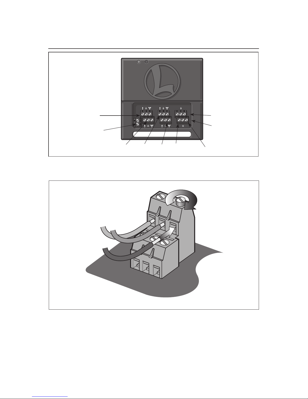
Connect three switch wires to the SC-
2 terminals. Begin with the ground
(common) for each switch. Listed below are
ground terminal locations for some popular
Lionel switches. Connect the ground terminal
of each switch to the center screws of each
terminal block on the SC-2.
HOW TO FIND THE
RIGHT POST
If you’re in doubt about which binding post
connects to the outside (ground) rail, check
it with a meter or continuity tester, available
from your local electronics supply store.
• On contemporary Lionel O gauge switches
(6-23010 and 6-23011), ground is terminal
number 2. Refer to Figure 4.
• On postwar 022 and MPC/early LTI
O gauge switches (5132 and 5133), O-31
(14062, 14063) and O-72 (65165, 65166)
ground is the center binding post. Refer to
Figure 5.
• On many O-27 switches, including the
O-42 and O-27 versions sold in the 1950s
(1122 and 1122), and during the modern
era (5121 and 5122e), ground is closest to
the switch motor. See page 10 for special
instructions for using O-27 with Command
control. Refer to Figure 6.
• On super O switches (where two posts are
together and one post is positioned on the
side) ground is the side post.
Each of the SC-2’s ground termi-
nals are independent of all other
ground terminals. You must
connect a ground wire for each
device to the center set screw on that
terminal.
When connecting the left and right terminal
wires, make sure the wire throwing the switch
“out” (curved) connects to the SC-2’s “Switch
Out” terminal (#3). The wire throwing the
switch “through” (straight) should connect to
the SC-2’s “Switch Through” terminal (#1).
To identify which wire controls which switch
function, begin by powering up each switch.
Touch each of the two remaining switch wires
to its ground terminal and note the action
of the switch. Once the functions have been
determined, power to the switch should be
disconnected until the wiring to the SC-2 is
completed.
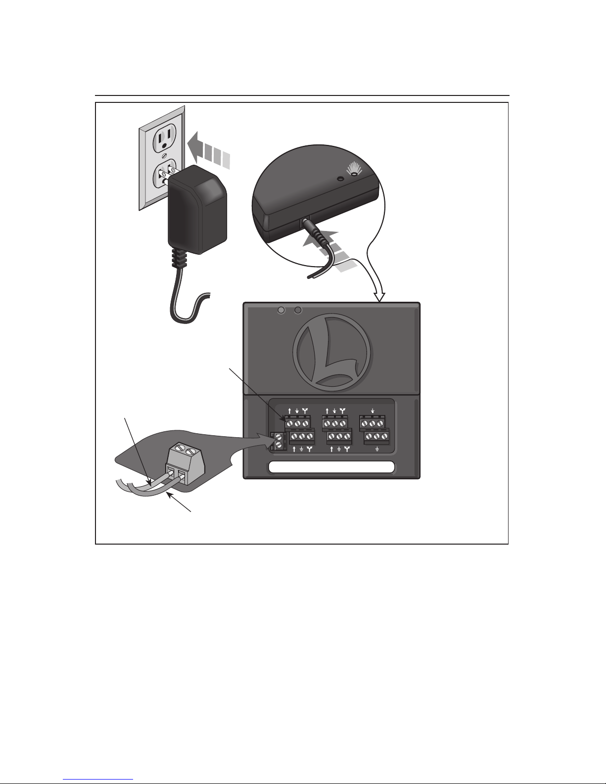
When a switch is properly connected to the
upper left terminals on the SC-2 and switch
power is on, the SC-2’s green light should
illuminate. This indicates the SC-2 is properly
powered.
Note!
Hint!

9
Connecting Lionel switches to the SC-2 (continued)
Installing the SC-2 on your railroad
ACC3 ACC4
ACC1 ACC2
1
2
3ATRACK
AUX.
3
1
2
2
1
3
#1 through (straight)
#2 common
#3 out (curved)
SC-2
You can still control your switches manually. The
manual controller is connected as shown above. No
modification is required to this wiring.
Note
Connect one switch
to these terminals to
power the SC-2 from
switch power
Switch
controller
(optional)
0-31 switch
6-23011
6-23010
Figure 4. Wiring Lionel O gauge switches
ACC3 ACC4
ACC1 ACC2
U
Accessory Power
Fixed Voltage Plug
Switch controller
(optional)
Figure 5. Wiring Lionel O-31 and O-72 gauge switches

10
Installing the SC-2 on your railroad
Modifying O-27 switches for use with the SC-2
O
-27 type switches receive their power from
variable track voltage. In order to operate
this type of switch with the SC-2 controller, you
need to make the following modifications to
allow the switch to operate from a fixed voltage
power source.
First, take the top cover off of the switch
by removing the screw. This will expose the
double coils. Next, find the two wires that are
located at the center of the two coils. These
wires are contained inside one piece of insula-
tion. Gently pull on the insulation to expose
the wires. Now, clip the two wires about 1/2˝
from the coils. Using electrical tape, wrap the
wire ends that come up from the bottom of
the switch. Use the heat from your soldering
iron to remove 1/4˝ of the varnish insulation
from the remaining wires, then twist the wires
together. Using your soldering iron, put a
small amount of solder on the ends of these
wires and solder a jumper wire to them. Wrap
this connection with electrical tape to keep it
from coming in contact with the coil housing.
Before you replace the switch cover, you
may need to cut a notch (using a hobby knife)
for the wire to come through. You may also
route the wire through the holes used to vent
any heat generated by the coils on top of the
cover. Replace the cover on the switch, then
attach the jumper wire to a fixed voltage power
source.
You will need to attach a ground wire from
this separate power source to the outside rail of
your track, or you can attach this ground wire
to the “U” post on the PowerMaster.
Your switches can now be operated using the
SC-2 Controller.
Control Rails
Ground
Coils and Plunger
Clip Wires
Here
Control Rails
Ground
Jumper Wire
(Connect to Fixed Voltage Power Source)
To SC-2
To SC-2
Figure 6. Wiring Lionel O-27 gauge switches

11
Connecting hi-rail switch motors to SC-2
The SC-2 can control high current switch
machines directly through its terminals.
Follow Figures 7 and 8 for proper installation.
Do not use the SC-2 to control any device that
draws more than 15 Amps when operating. The
controller can also be used with DC type switch
machines according to the wiring diagram
below. Additional parts are required for these
machines and are available through any elec-
tronics supply house.
Installing the SC-2 on your railroad
ACC3 ACC4
ACC1 ACC2
High current solenoid switch motors
(NJ International) less than 15 amps.
A
U
NJ1
switch
motor
The SC-2 can be powered from
your switch power supply if one
switch is connected to the upper
left terminal posts on the SC-2.
Note!
Figure 7. Wiring NJ1 switches

12
Connecting hi-rail switch motors to SC-2 (continued)
Installing the SC-2 on your railroad
ACC3 ACC4
ACC1 ACC2
DC-type Hookup
switch
motor
transformer
(12 VAC)
A
USwitch Motor
1N4001, 2, 3 or 4
470ς
1N4001, 2, 3, or 4
Wallpack
(required)
Note!
Parts needed for each DC-type switch motor:
2-1N4001, 1N4002, 1N4003, or 1N4004 diodes
1-470Ω2-watt resistor
Available from Newark Electronics or Radio Shack
(To find the nearest Newark Electronics Sales Office, call 1-800-463-9275.)
You must hold down the AUX1
and AUX2 buttons until the
switch has fully thrown.
Figure 8. Wiring DC-type switches

If you reprogram your SC-
2 switch or accessory ID#s,
your routes may not function
properly. We recommend that you
clear and reprogram all routes.
See page 18.
Program switch ID#’s
1, 2, 3, and 4
Command Base plugged in
Switch/turnout power ON
SC-2 ON
Slide SC-2 RUN/PROG switch to PROG
Press SW
Press 1 (the switch number)
Press SET
SC-2’s red light illuminates for-two
seconds
You have assigned ID# 1 to the first
switch connected to the SC-2. The
next switch ID#’s (2, 3, and 4) are
automatically assigned
Slide your SC-2 RUN/PROG switch to
RUN; repeat these steps for other
SC-2s installed on your railroad
The next SC-2 programmed
will be Switch #5 or higher
Example
Note!
SW ACC RTE TR ENG
WSTL / HRN
BELL
DIR
BOOST
AUX 1
COUPLER BRAKE
AUX 2
COUPLER
HALT
123
456
789
0
SW ACC RTE TR ENG
WSTL / HRN
BELL
DIR
BOOST
AUX 1
COUPLER BRAKE
AUX 2
COUPLER
HALT
1 2 3
4 5 6
7 8 9
0
SW ACC RTE TR ENG
WSTL / HRN
BELL
DIR
BOOST
AUX 1
COUPLER BRAKE
AUX 2
COUPLER
HALT
123
456
789
0
SET
13
Programming the SC-2 switch numbers
Every switch needs an ID#. Take the
time now to label your switches and
the terminals they connect to on the SC-
2. Start numbering with #1 on the first
SC-2 at the upper left corner. Follow the
numbering scheme shown in Figure 1 on
page 5.
SC-2 switch numbers are consecutive.
Only program the first switch position
on each SC-2. The next switch ID#s are
programmed automatically by the SC-2.
For example, if you program the first
switch connected to your SC-2 as switch #1,
the switch numbers on that SC-2 become
1, 2, 3, and 4 (1 through 6 if programmed
to control switches only). If you program
the first switch connected to your SC-2
as switch #9, the numbers become 9, 10,
11, and 12 (9 through 14 if programmed
to control switches only). See page 22 for
instructions to program the SC-2 in switch
only mode.
Choose switch numbers between
1 and 99 (99 switches total).
ID# 0 is reserved for clearing
the settings.
To program the switch numbers, be sure
the Command Base and SC-2 are both
powered up. Slide the SC-2 RUN/PROG
switch (see Figure 9) to PROG. Press SW,
the switch ID#, then SET. The SC-2’s red
light will turn on for two seconds. Now
slide the RUN/PROG switch back to RUN.
Note!
Note!
fig 8 page 11 SC-1 switch to program
PROG / RUN
Operating switches with your SC-2
Figure 9. RUN/PROG switch

Controlling switches with CAB-1
Now that you've programmed the
switch numbers, you can throw
the switches using the CAB-1 Remote
Controller.
To operate another switch,
you can just enter the
ID# and select OUT or
THROUGH without pressing
SW again. This "short-
hand" continues to work
until you press another
top-row address button
(ENG, TR, ACC, RTE).
If the switch operates
but throws to the wrong
position, swap the wires
connected to the outer set
screws of the SC-2 termi-
nals for that switch.
Operating switches with your SC-2
14
Throw switch #1 OUT
Press SW
Press 1
Press OUT
Switch #1 is now curved, or OUT
Throw Switch #12
THROUGH
Press SW
Press 12
Press THROUGH
Switch #12 is now straight, or THROUGH
Example
Example
WSTL / HRN
BELL
DIR
BOOST
AUX 1
COUPLER BRAKE
AUX 2
COUPLER
SW ACC RTE TR ENG
WSTL / HRN
BELL
DIR
BOOST
AUX 1
COUPLER BRAKE
AUX 2
COUPLER
HALT
123
456
789
0
SW ACC RTE TR ENG
WSTL / HRN
BELL
DIR
BOOST
AUX 1
COUPLER BRAKE
AUX 2
COUPLER
HALT
123
456
789
0
SW ACC RTE TR ENG
WSTL / HRN
BELL
DIR
BOOST
AUX 1
COUPLER BRAKE
AUX 2
COUPLER
HALT
123
456
789
0
SW ACC RTE TR ENG
WSTL / HRN
BELL
DIR
BOOST
AUX 1
COUPLER BRAKE
AUX 2
COUPLER
HALT
123
456
789
0
SW ACC RTE TR ENG
WSTL / HRN
BELL
DIR
BOOST
AUX 1
COUPLER BRAKE
AUX 2
COUPLER
HALT
123
456
789
0
WSTL / HRN
BELL
DIR
BOOST
AUX 1
COUPLER BRAKE
AUX 2
COUPLER
Note!
Note!

15
Creating routes around your railroad
Here’s a common scenario: to travel from
the main line to the yard, you must
travel on a certain route. In Figure 10, for
example, Switch #2 is THROUGH (straight),
Switch #4 is OUT (curved), and Switch #14
is THROUGH. With TrainMaster Command,
you can throw all those switches with a
single command—RTE.
Always check your RTE programming. Throw switches opposite the RTE
direction, then press RTE and the ID#. Your route should immediately throw.
To avoid overloading your power supply, switches in a route will operate in
consecutive order, one at a time.
You can add more switches to a route at any time.
Any switch can be part of any route. A route may consist of any number of
switches, although each switch may only be used once in the same route. Any
switch can be included in any number of routes, creating a wealth of possibili-
ties. Discover new pathways around your railroad with RTE. Routes are remem-
bered forever—or until you clear them.
Note!
Operating switches with your SC-2
Figure 10. Switches in a route

Creating routes around your railroad (continued)
Assign switches #2
(THROUGH),
#4 (OUT) and #14 (THROUGH)
to Route #1
You do not have to program a route
in sequential order. Any switch can
be added to any route at any time.
Establish the route; press RTE
Press 1 (the route number)
Press 2 (the switch number)
Press THROUGH
Press SET
SC-2’s red light illuminates for two
seconds.
Address the route; press RTE
Press 1 (the route number)
The SC-2 will operate previously
programmed switch #2 briefly.
Switch #2 is in the “through” direc-
tion on Route #1.
Press 4 (the switch number)
Press OUT
Press SET
SC-2’s red light illuminates for two
seconds.
Address the route;
press RTE
Press 1 (the route number)
The SC-2 will operate previously
programmed switch #2 and 4
briefly. Switch #4 is in the “out”
direction on Route #1.
Press 14
(the switch number)
Press THROUGH
Press Set
SC-2’s red light illuminates for
two seconds
Example
RTE
SW ACC RTE TR ENG
WSTL / HRN
BELL
DIR
BOOST
AUX 1
COUPLER BRAKE
AUX 2
COUPLER
HALT
1 2 3
4 5 6
7 8 9
0
SW ACC RTE TR ENG
WSTL / HRN
BELL
DIR
BOOST
AUX 1
COUPLER BRAKE
AUX 2
COUPLER
HALT
123
456
789
0
SET
SW ACC RTE TR ENG
WSTL / HRN
BELL
DIR
BOOST
AUX 1
COUPLER BRAKE
AUX 2
COUPLER
HALT
123
456
789
0
SW ACC RTE TR ENG
WSTL / HRN
BELL
DIR
BOOST
AUX 1
COUPLER BRAKE
AUX 2
COUPLER
HALT
1 2 3
4 5 6
7 8 9
0
SET
SW ACC RTE TR ENG
WSTL / HRN
BELL
DIR
BOOST
AUX 1
COUPLER BRAKE
AUX 2
COUPLER
HALT
1 2 3
4 5 6
7 8 9
0
You may find it helpful before program-
ming routes to make a list of all your
switches and their settings for each route.
Refer to this list when programming and to
identify routes later.
When a route is activated, there
will be a delay between the activa-
tion of each switch.
The SC-2 can control a maximum of nine
routes. When assigning a route ID#, choose
a number between 1 and 9. Refer to the
example below to create a route.
All SC-2’s must be on with the
RUN/PROG switches in the
RUN position during all route
programming. The route will
activate every time RTE and the
ID# is pressed during program-
RTE
SW ACC RTE TR ENG
WSTL / HRN
BELL
DIR
BOOST
AUX 1
COUPLER BRAKE
AUX 2
COUPLER
HALT
1 2 3
4 5 6
7 8 9
0
SW ACC RTE TR ENG
WSTL / HRN
BELL
DIR
BOOST
AUX 1
COUPLER BRAKE
AUX 2
COUPLER
HALT
123
456
789
0
SET
SW ACC RTE TR ENG
WSTL / HRN
BELL
DIR
BOOST
AUX 1
COUPLER BRAKE
AUX 2
COUPLER
HALT
123
456
789
0
RTE
SW ACC RTE TR ENG
WSTL / HRN
BELL
DIR
BOOST
AUX 1
COUPLER BRAKE
AUX 2
COUPLER
HALT
123
456
789
0
SW ACC RTE TR ENG
WSTL / HRN
BELL
DIR
BOOST
AUX 1
COUPLER BRAKE
AUX 2
COUPLER
HALT
123
456
789
0
Operating switches with your SC-2
Note!
Note!
Note!
You cannot remove an individual switch from RTE; you must clear the entire route
and start again.
If you make an error during RTE programming, do not press SET. You must start
over—press RTE, Route #, the switch number, its position, and then press SET.
16

Select any route you’ve programmed
by pressing RTE and entering the RTE
ID#. Make sure you press and hold the ID#
button for one full second. This ensures the
command is issued to every SC-2 on your
railroad.
When you are pressing the ID# button,
some of the switches may not actually throw
until you’ve released the button. Switches
activate at different times once you’ve
selected the route —this keeps your system
(and your railroad’s power supplies) from
overloading due to simultaneous activation.
Be sure to let one route operate completely
before selecting another. This will ensure
trouble-free operation of the SC-2’s.
Unlike switch control, there is no
“shorthand” for route control.
Each time you wish to activate
a route you must first press the
RTE key. This must be done even
if the last command issued was a
route activation.
17
Operating switches with your SC-2
Activating routes
After a route is programmed, you may
reprogram an individual switch setting
by following the steps on page 16. The
existing switch direction assignment (AUX1
or AUX2) will be reassigned.
You cannot delete individual
switches from a route assign-
ment. You must clear the entire
route and reprogram.
Modifying routes
activate Route #1
Press RTE
Press 1 for one full second
Route #1 has been selected:
Switch #2 is THROUGH, Switch
#4 is OUT, and Switch #14 is
THROUGH
Example
RTE
SW ACC RTE TR ENG
WSTL / HRN
BELL
DIR
BOOST
AUX 1
COUPLER BRAKE
AUX 2
COUPLER
HALT
123
456
789
0
Note!
Note!

Operating switches with your SC-2
18
Clear Route #1 (erase all
switch assignments)
Be sure the SC-2 RUN/PROG switch is set to
RUN.
Press RTE
Press 1 (the Route ID #)
The RTE will activate.
Press SET-Hold for 2 seconds.
The red LED on the SC-2 will blink on and
off for two seconds to indicate the route is
cleared.
Route #1 is now ready for new switch
assignments.
Example
RTE
SW ACC RTE TR ENG
WSTL / HRN
BELL
DIR
BOOST
AUX 1
COUPLER BRAKE
AUX 2
COUPLER
HALT
1 2 3
4 5 6
7 8 9
0
Clearing routes
SW ACC RTE TR ENG
WSTL / HRN
BELL
DIR
BOOST
AUX 1
COUPLER BRAKE
AUX 2
COUPLER
HALT
123
456
789
0
SET
To clear a route, press RTE, the
RTE ID#, then press and hold
SET for two seconds. The route
will operate one time then the
route will be cleared from the
SC-2. The red LED on the SC-2
will blink on and off for two
seconds to indicate the route is
cleared. Check that the route
has been cleared by setting some
switches for that route in the
opposite direction then pressing
RTE, then the RTE ID#. No
switches should operate.

19
Operating accessories with your SC-2
Most Lionel accessories can be
controlled by an SC-2. Start by
sequentially numbering the accessory termi-
nals with the adhesive labels (included).
Refer to Figure 11 for proper numbering
order. Each accessory ID# can be used for
either momentary or on/off functions. For
any given accessory number, press AUX1 for
Momentary operation of loaders and similar
products or press AUX2 to toggle the acces-
sory functions such as lights. Turn to pages
28-35 for wiring examples.
Keep in mind that accessories need to be
externally powered. If the SC-2 will only
operate accessories then you must either
power the SC-2 through the track auxiliary
power connection terminals or by a wall
pack. Operating accessories may be powered
by PowerMasters. This gives you keypad
control over their voltage levels. See your
Command Control instruction manual for
details.
Connecting accessories to the SC-2
ACC3 ACC4
ACC1 ACC2
ACC2
ACC3 ACC4
Accessory 2 momentary
Accessory 2 on/off
Common
Accessory 1 on/off
Accessory 1 momentary
Common
Figure 11. Accessory terminals
Note! Refer to pages 28-35 for accessory wiring diagrams.

20
Programming SC-2 accessory ID#’s
Just like switches, accessories
need ID#’s. To program the
ID#’s follow the example to the
left.
Accessory ID#’s on the SC-
2 are consecutive. When you
program the first of the accessory
terminals, you also program all
remaining accessory terminals.
Choose accessory ID#’s between
1 and 99 (maximum accessory
number is 99). Do not use 0
as an ID#. This is reserved for
clearing the settings.
Program accessory (ACC)
ID#’s 1 and 2
Command Base plugged in
SC-2 ON
Slide SC-2 RUN/PROG switch to PROG
Press ACC
Press 1 (the accessory number)
Press SET
SC-2’s red light illuminates for two seconds
You have assigned a ID# 1 to the first acces-
sory connected to the SC-2. The next acces-
sory is automatically assigned
ID# 2.
Slide your SC-2 RUN/PROG switch to RUN;
repeat these steps for other SC-2s installed
on your railroad.
The next SC-2 programmed will
be Accessory #3 or higher.
Example
Note!
SW ACC RTE TR ENG
WSTL / HRN
BELL
DIR
BOOST
AUX 1
COUPLER BRAKE
AUX 2
COUPLER
HALT
123
456
789
0
SW ACC RTE TR ENG
WSTL / HRN
BELL
DIR
BOOST
AUX 1
COUPLER BRAKE
AUX 2
COUPLER
HALT
123
456
789
0
SW ACC RTE TR ENG
WSTL / HRN
BELL
DIR
BOOST
AUX 1
COUPLER BRAKE
AUX 2
COUPLER
HALT
123
456
789
0
SET
Operating accessories with your SC-2
fig 8 page 11 SC-1 switch to program
PROG / RUN
Other manuals for SC-2
1
Table of contents
Other Lionel Controllers manuals

Lionel
Lionel Legacy PowerMaster 360W User manual

Lionel
Lionel CSM2 User manual

Lionel
Lionel LCS AMC2 User manual

Lionel
Lionel RAILROAD User manual

Lionel
Lionel TMCC BPC User manual

Lionel
Lionel TMCC User manual

Lionel
Lionel LCS BPC2 User manual

Lionel
Lionel 153IR User manual

Lionel
Lionel DZ-2500 User manual