FAN-DELAY REFRIGERATION DEFROST DRAINING
Indication released
F20 F14 F18F08
Indication locked (if enabled in F17)
5.4- Manual defrost
Todoamanualdefrost,regardlessoftheprogramming,keeppressed for4seconds,untilappearsthe
indication .
If the instrument is in defrost and you want to finish it, follow the above instructions, until appears the
indication .
5.5- How to determine the end defrost by temperature
a)
b)
c)
d)
Adjustthefollowfunctionswithmaximumvalues:
-Refrigerationtime(F08=999min)
-Evaporatortemperatureforenddefrost(F13= )
-Maximumdurationofdefrost(F14=90min)
Waituntilanicelayertobecreatedontheevaporator
Doamanualdefrost,pressing for4seconds,untilappear .
Observethemeltingprocess.
75.0ºC/167°F
e)
f)
g)
h)
Waituntilmeltallicelayerontheevaporatortoconsiderthedefrostfinished.
ChecktheevaporatortemperaturereadbythesensorS2atthismoment,pressingthekey (seeitem5.3)
andcopythisvaluetothefunctionF13-Evaporatortemperature(S2)forenddefrost.
Assecurity,adjustagainthefunctionF14- thatdependsofthedefrosttype.
NowadjustthefunctionF08-
Maximum duration of defrost,
Exemple: Electrical defrost (resistance) =45 minutes as maximum
Defrost for by hot gas = 20 minutes as maximum
Refrigeration time with the desired value.
5.7- Minimum and maximum temperatures register
Press , soon appears and the minimum and maximum temperatures of S1 sensor (ambient
temperature). After soon appears and the minimum and maximum temperatures of S2 sensor
(evaporator).
Note: To reset the registers keep pressed the key during the visualization of the minimum and
maximumtemperaturesuntil tobeshowed.
5.8SELECTION OFTHEUNIT(Cº/Fº)
Inorder to define theunit that the instrument will operate in, enter function“F01” with the accesscode
“231”and confirmwith the key.Press the key and the indication willappear.Press
tochoosebetween or andconfirm.Afterselectingtheunitthe messagewill
appear, and the instrument will return to the function “F01”. Every time that the unit is changed, the
parametersshouldbereconfigured,sincetheyassumethe“standard”values.
SET
SET
6. ELECTRICAL CONNECTIONS
Power
supply
Over the specifield current
use a contactor.
Loads
supply
Sensor
(black)1
Sensor
(gray)2
- The sensor S1 (black) must be in the ambient.
- The sensor S2 (gray) must be placed in the evaporator through metallic cramp.
90 - 264Vac
45678910 11 12
321 21
(0) (12V) (24V)
12Vac/dc
24Vac/dc
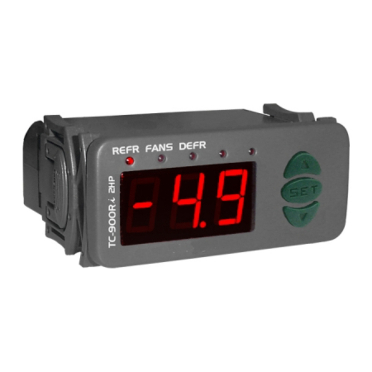
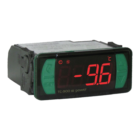
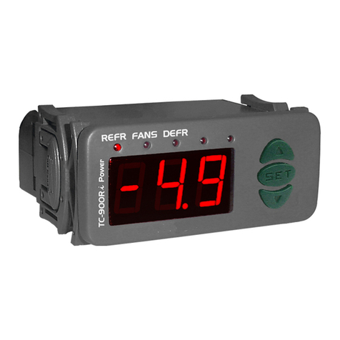
TC-900RiLPower
4-5
4-6
4-5
90 - 264Vac
TC-900Ri Power
COMPRESSOR
16(8)A / 250Vac 1HP
DEFROST
8(3)250Vac 1/4HP
FANS
5(3)A / 250Vac 1/8HP
5.6- Indicatorsandalarms
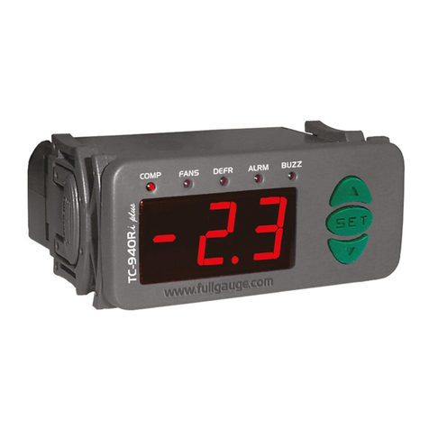
Theled'ssignalsindicatethestatusoftheoutputs:
Compressororliquidgassolenoid
Evaporatorfans
Defrost(resistanceorhotgas)
Ambientsensordisconnectedoroutofrange.
Evaporatorsensordisconnectedoroutofrange.
Highambienttemperaturealarm.
Whenever the defrost ends due to time and not temperature, a point located in the lower right-
hand corner of the display will continue to blink until the next defrost, and will indicate the following
possibilities:
-Theintervalbetweendefrostcyclesistoolong;
-Thereareburnedheatingelements;
-Thehotgasisnotcirculating;
-Thereisanonworkingfanorthesetmaximumdefrosttimeisnotenough;
Invalidconfigurationparameters;
-Inthissituationtheoutputsareturnedoff;
-Checkwhichparametershaveinvaliddataandcorrectthemtoreturntonormaloperation.
REFR:
FANS:
DEFR:
F14-Maximumdurationofdefrost(forsecurity)
F19-Evaporatortemperature(S2)forfanreturnafterdraining(fan-delay)
F20-Maximumtimeoffanreturnafterdraining(fan-delay)
F21-Fanonwithcompressoroff
F22-Fanstoppedforhightemperatureinevaporator
F23-Intensityofthedigitalfilterappliedtothesensor1(0-off)
Thisfunctionservestoadjustthemaximumvalueoftimefordefrost.Ifevaporatortemperaturedoesnot
reach the configured value in F13 in this period a point will blink in the right down side of display
indicatingthatendofdefrostocurredfortimeandnotfortemperature.
The fan-delay cycle starts after draining. The refrigeration output (REFR) is active, therefore the
ambienttemperatureishigh,butthefanisactivatedonlyafterthetemperatureinevaporatorislessthan
the adjusted value. This process is necessary to remove the heat that still exists in the evaporator
becauseofdefrost,preventing totransferthisheattotheambient.
Forsecurity,ifthetemperatureintheevaporatordoesnotreachtheadjustedvalueinF19orsensorS2
isdetached,thefan-delaywillhappenontheadjustedtimeinthisfunction.
Duringtherefrigerationcycle,thefanactivationmaydependonthecompressorstatus.
"0"=Thefanisactivedonlywhilethecompressorisactive.Thisalternative,insomecases,allowsgreat
economyofelectricenergy.
"1"=Thefaniskeptonduringallrefrigerationcycle.
It has the purpose of cycling the evaporator ventilation until the ambient temperature approaches the
desired temperature in the refrigerating installation project, preventing high temperatures and
pressuresthatcandamagethecompressor.Ifthetemperatureinevaporatorexceedtheadjustedvalue,
thefanisturnedoffandturnedonagainwithafixedhysteresisof2°Cbelowthisvalue.
This filter aims at simulating an increase of the mass of environment sensor (S1), thus increasing its
responsetime(thermalinertia).Thelargerthevalue adjusted inthisfunction,thelongest the response
timeofsensorS1.
Atypical applicationrequiring this filteris the freezerfor ice creamor frozen goods,because when the
door is opened a hot air mass reaches the sensor directly, causing the indication of the measured
temperaturetorisequicklyandthecompressortobeactivatedunnecessarilymanytimes.
The end of defrost by time (which is not desired) can happen on the following situations:
-Adjusted temperature too high
- Maximum time of defrost too short
- Detached sensor or without contact with evaporator
Example:
(F13)
(F14)
F15-Fanturnedonduringdefrost
F16-Defrosttype
F17-Lockedtemperatureindication(S1)duringdefrost
F18-Drainingtime(drippingofdefrostwater)
Itmakespossiblethefanfunctioningduringdefrost.
Naturaldefrostorby resistances installed outsidetheevaporator.
"0"=Electricaldefrost (resistances),wherethedefrostoutputisactive.
"1"=Defrost by hotgas,wherecompressoranddefrostoutputsareactives.
Thisfunctionpreventsthatambienttemperatureelevationduringdefrostbevisualized,keepingthelast
indication before defrost. The indication is released again in the initial of refrigeration cycle, after fan-
delay.
Necessarytimefordripping,itmeans,fordrainingthelastwaterdropsofevaporator.Alltheoutputsare
keptoff.Ifthisstagewillnotbedesired,adjustthistimefor“zero”.
5.OPERATION
5.1- Parameters visualization
a)
b)
c)
d
e)
a)
b)
c) 5.1-b 5.1-c
Pressatthesametime and for2secondsuntilappear ,releasingthemafterthat.
Soon,appears .
Use and toaccessthedesiredfunction.
Afterselectingthefunction,press (shorttouch)tovisualizetheconfiguredvalue.
)Pressagain (shorttouch)toreturnthefunctionsmenu.
Toreset the menu and return to normal operation(temperature indication), press until appear
.
AccessthefunctionF01bypressingatthesametime and for2secondsuntil appear ,
releasingthenafterthat.Soonwillappear ,andthenpress (shorttouch).
Use and toentertheaccesscode(123),andthenpress .
Selectthedesiredfunctionandvisualizetheconfiguredvalue(seeitens and ).
5.2- Parameters configuration
SET
SET
SET
SET
SET
d)
e)
Use and tochangethevalueandthenpress torecordtheconfiguredvalueandreturn
tothefunctionsmenu.
Toreset the menu and return to normal operation(temperature indication), press until appear
.
SET
SET
5.3-Process stage,elapsed time and evaporatortemperature (S2)
Press . The stage of the process will appear, the elapsed time (in minutes) and evaporator
temperature(S2).
Incaseofdetachedsensorortemperatureoutspecifiedrangewillappear .
Processstages: Initialdelay(delaytostartthecontrol)
Fan-delay(delaytofanreturn)
Refrigeration
Defrost
Draining
