manuals.online logo
Brands
  1. Home
  2. •
  3. Brands
  4. •
  5. Stiga
  6. •
  7. Lawn Mower
  8. •
  9. Stiga GRASSLAND MOWER 53 CM User manual

Stiga GRASSLAND MOWER 53 CM User manual

Other Stiga Lawn Mower manuals

Stiga ESTATE PRO 25 E 25 E User manual

Stiga

Stiga ESTATE PRO 25 E 25 E User manual

Stiga READY 85 M User manual

Stiga

Stiga READY 85 M User manual

Stiga COLLECTOR 45 COMBI EL User manual

Stiga

Stiga COLLECTOR 45 COMBI EL User manual

Stiga PARKPRO 16 16 User manual

Stiga

Stiga PARKPRO 16 16 User manual

Stiga DECK PARK 121 M User manual

Stiga

Stiga DECK PARK 121 M User manual

Stiga MCS 474 Series User manual

Stiga

Stiga MCS 474 Series User manual

Stiga MP2 504 Series User manual

Stiga

Stiga MP2 504 Series User manual

Stiga PARK RANGER User manual

Stiga

Stiga PARK RANGER User manual

Stiga Villa 2WD Series User manual

Stiga

Stiga Villa 2WD Series User manual

Stiga EW 330 Series User manual

Stiga

Stiga EW 330 Series User manual

Stiga Cruiser 480  Li 80 series User manual

Stiga

Stiga Cruiser 480 Li 80 series User manual

Stiga TITAN 20 B User manual

Stiga

Stiga TITAN 20 B User manual

Stiga MULTICLIP 50 S EURO User manual

Stiga

Stiga MULTICLIP 50 S EURO User manual

Stiga SCM 240 R User manual

Stiga

Stiga SCM 240 R User manual

Stiga NJ 92 Series User manual

Stiga

Stiga NJ 92 Series User manual

Stiga MP2 504 Series User manual

Stiga

Stiga MP2 504 Series User manual

Stiga EL 420 User manual

Stiga

Stiga EL 420 User manual

Stiga EXPERIENCE e-Ride C500 User manual

Stiga

Stiga EXPERIENCE e-Ride C500 User manual

Stiga PARK 4WD PRO Svan User manual

Stiga

Stiga PARK 4WD PRO Svan User manual

Stiga Garden Compact User manual

Stiga

Stiga Garden Compact User manual

Stiga MPST 84 Li 48 V1 User manual

Stiga

Stiga MPST 84 Li 48 V1 User manual

Stiga READY 85 M User manual

Stiga

Stiga READY 85 M User manual

Stiga COLLECTOR 45 S User manual

Stiga

Stiga COLLECTOR 45 S User manual

Stiga VILLA MASTER 13-2721-13 User manual

Stiga

Stiga VILLA MASTER 13-2721-13 User manual

Popular Lawn Mower manuals by other brands

RHINO 1958 parts manual

RHINO

RHINO 1958 parts manual

Wolf Garten Compact plus 40 B instruction manual

Wolf Garten

Wolf Garten Compact plus 40 B instruction manual

Cub Cadet LTX 1045 brochure

Cub Cadet

Cub Cadet LTX 1045 brochure

GGP ITALY SPA CR/CS 434 SERIES Operator's manual

GGP ITALY SPA

GGP ITALY SPA CR/CS 434 SERIES Operator's manual

Challenge CH18V2 Original manual

Challenge

Challenge CH18V2 Original manual

TALEN TOOLS AVR HGM30 manual

TALEN TOOLS

TALEN TOOLS AVR HGM30 manual

DEWEZE ATM-725 Operation and service manual

DEWEZE

DEWEZE ATM-725 Operation and service manual

Weed Eater 180083 owner's manual

Weed Eater

Weed Eater 180083 owner's manual

Husqvarna Poulan Pro PP185A42 Operator's manual

Husqvarna

Husqvarna Poulan Pro PP185A42 Operator's manual

Better Outdoor Products Quick Series Operator's manual

Better Outdoor Products

Better Outdoor Products Quick Series Operator's manual

Cub Cadet 23HP Z-Force 60 Operator's and service manual

Cub Cadet

Cub Cadet 23HP Z-Force 60 Operator's and service manual

MTD 795, 792, 791, 790 Operator's manual

MTD

MTD 795, 792, 791, 790 Operator's manual

Toro Groundsmaster 3505-D Service manual

Toro

Toro Groundsmaster 3505-D Service manual

Dennis FT 610 instruction manual

Dennis

Dennis FT 610 instruction manual

MTD 126-220-000 owner's guide

MTD

MTD 126-220-000 owner's guide

Toro 74806 Operator's manual

Toro

Toro 74806 Operator's manual

Stihl RMA 443 PV instruction manual

Stihl

Stihl RMA 443 PV instruction manual

Yard-Man 3700-0 Operating manual and parts list

Yard-Man

Yard-Man 3700-0 Operating manual and parts list

manuals.online logo
manuals.online logoBrands
  • About & Mission
  • Contact us
  • Privacy Policy
  • Terms and Conditions

Copyright 2025 Manuals.Online. All Rights Reserved.

Tosaerba falciatutto 53 cm.
Sichel-Mülchmäher 53 cm.
Grassland mower 53 cm.
Tondeuse débroussailleuse de 53 cm.
Cortacésped 53 cm.
Istruzioni d’uso
Bedienungsanweisung
Operating instructions
Mode d’emploi
Instrucciones de uso
AVVERTENZE: La presente nota di utilizzo deve essere integrata dalla lettura e dall’osservanza delle norme
prescritte nel manuale uso e manutenzione della macchina.
- Il falciatutto è indicato solamente per l’uso professionale ed in proprietà private.
- PERICOLO DI LANCIO OGGETTI: occorre allontanare tutte le persone, escluso l’utilizzatore, dalla zona di lavoro.
- Effettuare tutte le operazioni di manutenzione e di regolazione con il motore spento ed il cappuccio candela staccato,
PERICOLO DI LESIONI.
MONTAGGIO DEL FALCIATUTTO:FIG.1-Amotorefermoe conla macchinain posizioneorizzontale, inserireper metàil pernodel
tosaerba (1) nella sede dell’attacco rapido (2). Montare la cinghia (3) e portare a fine corsa il perno; inserire le molle (4) nei
rispettivi ganci (5) e successivamente nei fori (6). FIG. 2 - Fissare il coperchio in polipropilene (A) al supporto inferiore (B) tramite
le 5 viti autofilettanti (C), quindi togliere le 2 viti (D) del motocoltivatore per fissarle al coperchio.
REGOLAZIONE DELL’ALTEZZADI TAGLIO:Allentare le viti posteriori (E), togliere quelle anteriori (F) ed inserirle in uno dei fori di
regolazione (G) a seconda dell’altezza a cui si desidera effettuare il taglio. Premere sul tubo di scorrimento (H) in modo da
renderlo orizzontale al terreno, quindi serrare le viti.
MANUTENZIONE: - Dopo ogni uso è necessario pulire accuratamente il tosaerba, utilizzando stracci o una robusta spazzola,
NONUSAREACQUANELLAZONAADIACENTEALMOTORE.
- Controllare periodicamente l’usura del ferodo freno lama e mantenere ingrassati il perno (8) ed il tubo (9) del sistema
frenante.
- Se durante il taglio le punte dell’erba dovessero risultare ingiallite e strappate, occorre riaffilare la lama.
- Per motivi di sicurezza è possibile affilare la lama asportando materiale fino ad un massimo di 6 mm, sotto tale misura è
necessaria la sostituzione, IMPIEGANDO SOLO RICAMBI ORIGINALI.
ACHTUNG: Vor der Montage und Inbetriebnahme unbedingt die Bedienungsanweisung beachten !
- Das Anbaugerät Sichelmäher (Mulchgerät) ist ausschließlich für den üblichen Einsatz in der Land- und Forstwirtschaft,
Grunflachen und Anlagenpflege bestimmt. Jeder darüber hinausgehender Gebrauch gilt als nicht bestimmungsgemäß.
- Gefahr durch Fremdkörper auf der zu mähender Fläche. Deshalb ist es unbedingt erforderlich auf Fremdkörper zu achten und
diese zu entfernen. Der Bedienende hat die Verantwortung gegenüber Dritten und muß daher Sorge tragen, daß sich Diese
außerhalb des Arbeitsbereiches aufhalten !
- Wartungs- und Reinigungsarbeiten am Gerät sowie die Schnitthöhenverstellung dürfen nur bei stillgesetzem Motor
und abgezogenem Zündkerzenstecker mit geeignetem Werkzeug vorgenommen werden ! Verletzungsgefahr !
ANBAU DES SICHELMÄHWERKS (MULCHGERÄT): BILD 1 - Die Maschine mit stillstehendem Motor in waagrechte Position
bringen. Den Tragzapfen des Sichelmähers (1) zur Hälfte in das Tragrohr (2) der Maschine einschieben. Danach den
Antriebskeilriemen (3) auf die Keilriemenscheibe der Maschine aufziehen. Dabei wird der Tragzapfen in die richtige Position bis
zumAnschlag der Maschine gebracht. Die Rückholfeder (4) in die Fanghaken (5) der Maschine bringen. Danach die Rückholfeder
spannen und die enden (Haken) in Bohrung (6) einhaken !
BILD 2 - Die Schutz- und Abdeckhaube (A) wird mit 5 Stück Schrauben (C) an den Träger (B) montiert. Danach die 2 Stück
Schrauben (D) an der Maschine demontieren uund zusammen mit der Schutzhaube wieder montieren.
EINSTELLUNG DER SCHNITTHÖHE: Die Schrauben im Langloch (E) lösen. Danach die Schraube (F) an dem Lochsegment in
die gewünschte Schnitthöhe einschrauben. Dabei ist zu beachten, daß die Gleitschiene (H) waagerecht am Boden aufliegt.
Schrauben (E) und (F) festziehen.
WARTUNG:
- Nach jeder Benutzung ist der Sichelmäher sorgfältif mit einem Besen oder Bürste zu reinigen. Vorsicht beim abspritzen mit
Wasser!IMMOTORBEREICH ISTWASSER VERBOTEN !
- Wichtig: Die Bremsbeläge sind periodisch auf Verschleiß zu kontrollieren. Der Bolzen (8) in dem Rohr (9) der Bremsvorrichtung
muß täglich geschmiert werden.
- Wenn kein gutes Schnittbild mehr erreicht wird, z.B. wenn die Schnittfläche an der Grasspitzen ausgerissen sind, muß das
Messer nachgeschliffen werden!
- Aus Sicherheitsgründen kann das Mähmesser nur bis Ca. 6 mm. nachgeschärft werden. Unter diesen Maßen kann eine
Unwucht und somit eine Gefahr entstehen.
WARNING: - This note of use must be integrated by the reading and by the conformity of the rules writed in the
Fig. 1 Fig. 2
I
D
UK
instruction manual.
- The grassland mower is suitable only for a professional use and in private property.
- DANGER OF THROWING OBJECTS: it’s necessary remove everybody near the machine, excluded the person that is working.
- Effect all operation of maintenance and of adjustment with the engine off and the cap of the sparking plug taken off, DANGER
OFINJURY.
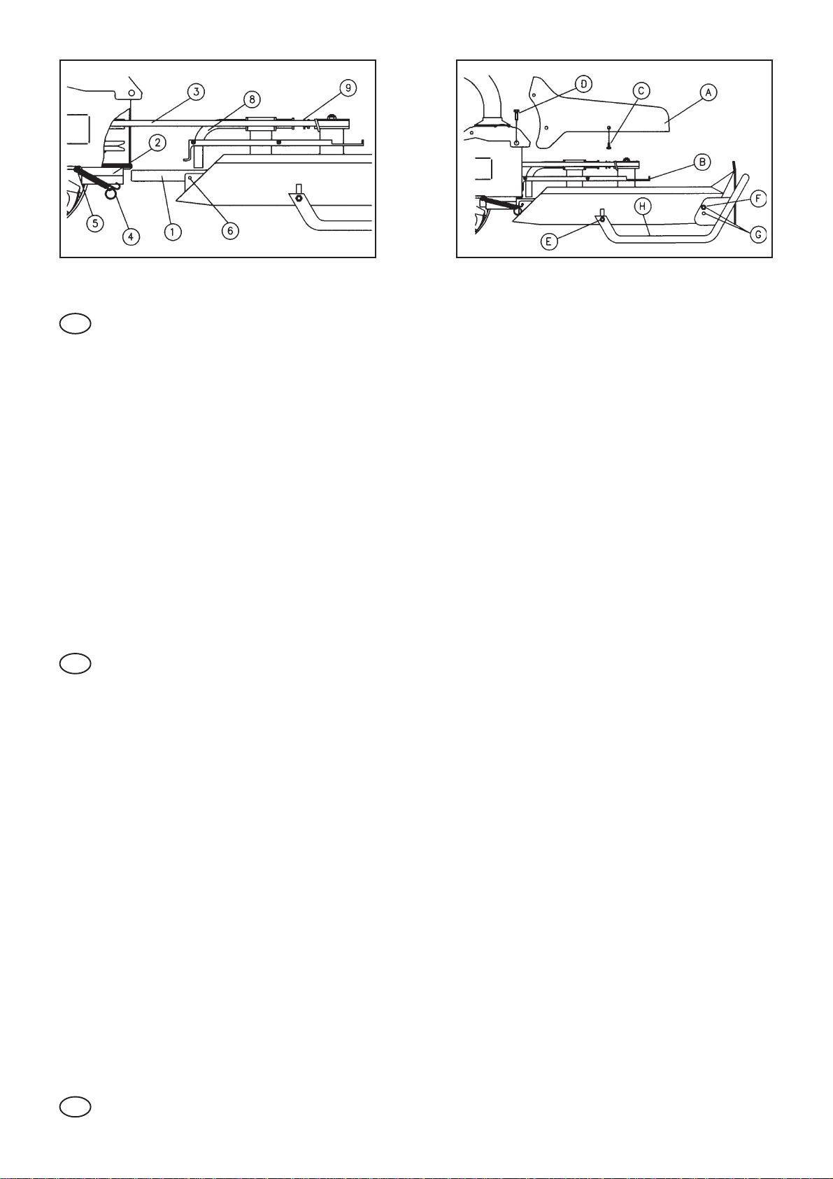
ASSEMBLING OF THE GRASSLAND MOWER: FIG.1 -Atengine offand withthe machinein horizontalposition,connect half-pivot
of the grassland mower (1) in the couple of the quick connection (2). Assemble the belt (3) and connect the whole pivot; connect
the springs (4) in the respective hooks (5) and then in the holes (6). FIG. 2 - Fix the cover in polypropylene (A) to the cover support
(B) through the 5 screw auto-cutting (C), so remove the 2 screw (D) of the motor-cultivator to fix them to the cover.
REGULATION OF CUTTING HEIGHT: Loosen the hind screws (E), remove those ones rare (F) and connect them in one of the
holes of regulation (G) according to the height to which you want to effect the cut. Press on the creeping tube (H) in way to make
it horizontal as the ground, so tighten the screws.
MAINTENANCE:
- After use it is necessary clean the grassland mower, utilizing rags or a strong brush, DO NOT USE WATER IN THE COUPLE
ADJACENTTO THE ENGINE.
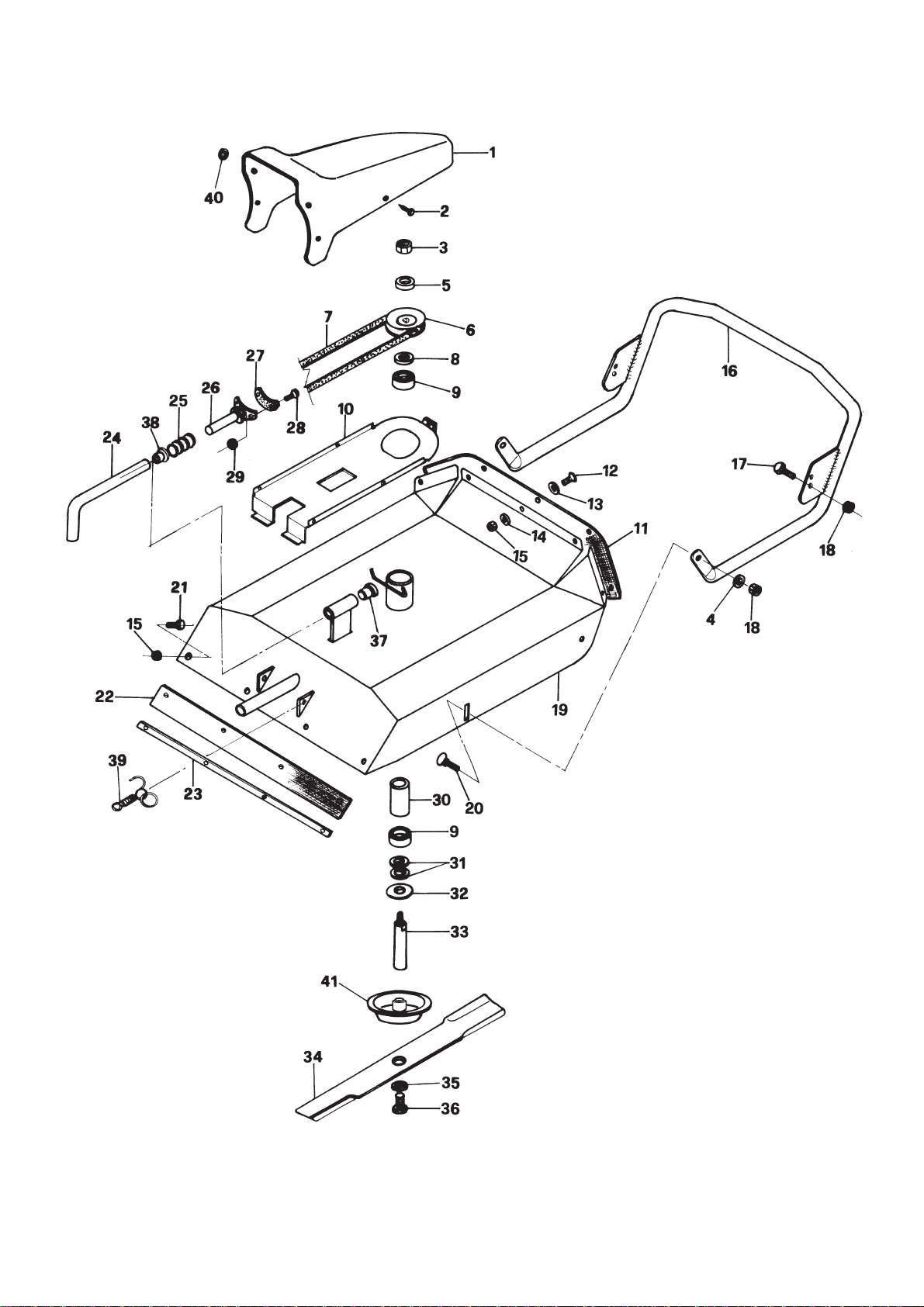
- Control periodically the wear and tear of the blade brake and mantein greased the pivot (8) and the tube (9) of the braking
system.
- If during the cutting the painting of the grass are of yellow colour or pulled, it’s necessary put an edge on the blade.
- For safety’s sake it’s possible to put an edge on the blade remaining the material at the most to 6 mm; below this measure
it’s necessary the replacement, USING ONLYORIGINAL SPARE PARTS.
INSTRUCTIONS: - Il faut lire attentivement cette notice d’instructions et aussi tous les renseignements du mode
d’emploi de la machine.
- La débroussailleuse est conseillée seulement pour un emploi professionnel et dans des proprietées privées.
- DANGER DE JET D’OBJETS: il faut éloigner tout le monde, sauf l’utilisateur, de la zone de travail.
- Toute intervention sur la machine, que ce soit d’entretien, de nettoyage ou de reglage ne doit s’effectuer que moteur coupé,
lame arrêtée et capuchon de la bougie enlevé, DANGER DE BLESSURES.
MONTAGE DE LADEBROUSSAILLEUSE: FIG. 1 - Le moteur étant arrêté et la machine en position horizontale, introduire jusqu’à
moitié l’axe (1) de la débroussailleuse dans l’emplacement de l’attelage rapide (2). Monter la courroie (3) en portant l’axe de
guidage en fin de course; fixer les ressorts (4) dans les crochets respectifs (5) puis dans les trous (6). FIG. 2 - Monter le capot
en polypropylène (A) au support inférieur (B) par les 5 vis filetées (C), puis enlever les 2 vis (D) de la machine pour les fixer au
capot.
REGLAGE DE LA HAUTEUR DE COUPE: Desserrezles visarrière (E),enlever celles avant(F) etles inserer dansun destrous de
reglage (G) sélon le niveau de hauteur auquel on veut faire le coupe. Appuyer sur le tube (H) de façon qu’il soit horizontal à la
surface du sol, puis serrer les vis.
ENTRETIEN:
- Après chaque utilisation il est indispensable de nettoyer avec soin la débroussailleuse en employant une brosse dure, NE PAS
EMPLOYER DE L’EAU TOUTPRES DU MOTEUR.
- Contrôler périodiquement l’usure de la garniture des freins de la lame et maintenir graissé le goujon (8) et le tube (9) du
dispositif de freinage.
- Si les pointes du gazon deviennent jaunes ou déchirées pendant le coupe, il faut réaffuter la lame.
- Pour des raisons de sécurité il est possible de réaffuter la lame en enlevant du metal jusqu’au maximum de 6 mm; au-
dessous de cette mésure il est indispensable de remplacer en UTILISANT SEULEMENT DES PIECES D’ORIGINE.
ADVERTENCIA: La presente nota de uilización tiene que ser integrada con la lectura y el respecto de las normas
prescriptas en el manual de uso y manutención de la máquina.
- El cortacéspedes es adapto sólo para el uso profesional y en propriedades particulares.
- PELIGRO DE LANZAMIENTO OBJETOS: es necesario alejar qualquier persona, con excepción del operador, de la zona de
trabajo.
- Proceder a las operaciones de mantenimiento y de regulación con el motor apagado y el capuchón de la bujía quitado, hay
PELIGRO DE LESIONES.
MONTAJE DEL CORTACÉSPED Fig. 1: con el motor apagado y la máquina en posición horizontal, insertar hasta la mitad de su
longitud el perno del cortacésped (1) en el asiento del enganche rápido (2).
Montar la correa (3) y llevar hasta el final de su longitud el perno; insertar los muelles (4) en los correspondendientes
agujeros (6).
Fig. 2: sujetar la tapa en polipropileno (A) al soporte inferior (B) con los 5 tornillos autorroscantes (C); luego quitar los 2
tornillos (D) del motcultor para sujetarlas a la tapa.
REGULACIÓN DE LA MEDIDA DE CORTE Aflojar los tornillos posteriores (E), quitar los tornillos anteriores (F) e insertarlas en
uno de los agujeros de regulación (G) según la medida de corte que se quiere obtener.
Apretar el tubo de deslizamiento (H) hasta que se encuentre paralelo al suelo, luego cerrar los tornillos.
MANTENIMIENTO Después de cada utilización, es necesario limpiar el cortacéspedes con cuidado, utilizando una escobilla
o trapos.NUNCAUTILIZEAGUAPARALIMPIARLAZONACONTIGUAALMOTOR.
- Aconsejamos controlar periodicamente el nivel de desgaste del ferodo del freno hoja y mantener el engrase del perno (8)
y del tubo (9) del sistema de frenado.
- Caso notara que durante las operaciones de corte las puntas del prado resultan amarillentas o arrancadas, esto significa que
hay que afilar de nuevo la hoja de corte.
- Por razones de seguridad es posible afilar la hoja (quitando material) sólo hasta los 6 mm; bajo de este límite es necesario
sostituir la lama misma, ACONSEJAMOS MONTAR SÓLO REPUESTOS ORIGINALES.
F
E
Cod. 32.1465.010 12/2008
132.1400.900
226.0050.219
381.4645.000
484.3708.000
526.0005.232
626.1005.200
732.1005.195
823.1005.256
981.2594.050
10 32.1400.278
11 32.1400.904
12 86.2168.000
13 84.3812.000
14 84.3619.000
15 81.4548.000
16 32.1400.150
17 86.2494.000
18 81.4588.000
19 32.1400.052
20 86.2786.100
21 86.1998.000
22 32.1400.906
23 32.1400.142
24 32.1400.248
25 34.1010.320
26 32.1400.270
27 32.1400.260
28 86.1929.100
29 81.4517.010
30 32.1400.222
31 27.0013.596
32 23.0330.209
33 32.1400.215
34 32.1400.227
35 84.6000.300
36 26.0050.201
37 34.1012.128
38 34.1012.304
39 26.1005.906
40 84.3713.000
41 32.1400.230