2
EN
d. Make sure that the blades are replaced
only with suitable spare parts.
e. Make sure the batteries are recharged
using the correct charger recommend-
ed by the manufacturer. Incorrect use
can cause electric shock, overheating
or leakage of corrosive liquid from the
battery.
f. In case of electrolyte leaks, wash with
water / neutralizing agent and consult a
doctor in case of contact with eyes, etc.
g. Machine maintenance must be carried
out in accordance with the manufactur-
er's instructions.
Residual Risks
- Although the product complies with all
safetyrequirements,additionalrisksmay
stillexistduetoimproperinstallationand/
orunforeseeablesituations.Therefore,it
is necessary to keep the area on which
the product operates free of objects,
persons and animals, and to inform
everyone who may have access even
if only occasionally, to the work area, of
the possible hazards.
- In the event of thunderstorms with risk
of lightning and in anticipation of bad
weather conditions in general, it is rec-
ommended not to use the product and
todisconnectallperipheraldevicesfrom
themains.Tousethe product,reconnect
peripherals to the mains following the
manual's instructions.
1.2. PRODUCT DESCRIPTION
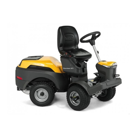
The robot lawn mower (Fig. 2.A) is designed and built to
automatically cut garden grass at any time of day and night.
cut, the robot lawn mower can be programmed to work on
several areas delimited by a virtual perimeter and connected
by virtual transition routes.
When operating, the robot lawn mower mows the area
delimited by the virtual perimeter (Fig. 2.B). When the robot
lawn mower is close to the virtual perimeter (Fig. 2.B) or
encountersanobstacle(Fig.2.C)changestrajectoryaccording
to the selected navigation strategy:
Therobotlawnmowermowsthedelimited lawnautomatically
and completely.
The product operates via satellite signals and requires the
installationof achargingbase(Fig.2.F,2.G)andan integrated
satellite reference station (Fig. 3.C), that can be installed
separately.The robot lawn mower and the satellite reference
with SIM cards.The robot lawn mower operating technology
is based on the communication of data between the STIGA
Cloud and the robot itself.The subscription fee is mandatory
in order to operate the robot lawn mower and is based on the
amount of data required. A smartphone is also required for
the product to be used.
Any other usage may be hazardous and harm persons and/
or damage things. Improper use includes (for example, but
not limited to): transporting people, children or animals on
the machine; being transported by the machine; using the
machine to pull or push loads; using the machine for cutting
non-grass vegetation.
NOTE: The subscription fee is mandatory in order to
operatetherobotlawnmowerandisbased ontheamount
of data required.
1.3. SYMBOLS AND NAMEPLATES
WARNING:
Read the user instructions before starting
the product.
WARNING:
Danger of projections of objects against
the body.
Keep an adequate safe distance from the
WARNING:
Do not put hands and feet near or under the
opening of the cutting means.
Removethedisablingdevicebeforeoperating
on the machine or before lifting it.
WARNING:
Do not put hands and feet near or under the
opening of the cutting means.
Do not stand on the machine.
BAN:
Makesurethattherearenopeople(especially
machine.
BAN:
Do not use high pressure cleaners on the
supply unit (Charging Base and Reference
Protectionrating against the ingressofsolids
