when the engine is idling, have the machine
checked by your servicing dealer. STIHL recom‐
mends an authorized STIHL servicing dealer.
Take special care in slippery conditions (ice, wet
ground, snow), on slopes or uneven ground.
Watch out for obstacles: Roots and tree stumps
which could cause you to trip or stumble.
Always stand on the ground while working, never
on a ladder, work platform or any other insecure
support.
Be particularly alert and cautious when wearing
hearing protection because your ability to hear
warnings (shouts, alarms, etc.) is restricted.
To reduce the risk of accidents, take a break in
good time to avoid tiredness or exhaustion.
Work calmly and carefully – in daylight conditions
and only when visibility is good. Stay alert so as
not to endanger others.
Your power tool produces toxic
exhaust fumes as soon as the engine
is running. These fumes may be col‐
orless and odorless and contain
unburned hydrocarbons and benzol.
Never run the engine indoors or in
poorly ventilated locations, even if
your model is equipped with a cata‐
lytic converter.
To reduce the risk of serious or fatal injury from
breathing toxic fumes, ensure proper ventilation
when working in trenches, hollows or other con‐
fined locations.
To reduce the risk of accidents, stop work imme‐
diately in the event of nausea, headache, visual
disturbances (e.g. reduced field of vision), prob‐
lems with hearing, dizziness, deterioration in abil‐
ity to concentrate. Apart from other possibilities,
these symptoms may be caused by an exces‐
sively high concentration of exhaust gases in the
work area.
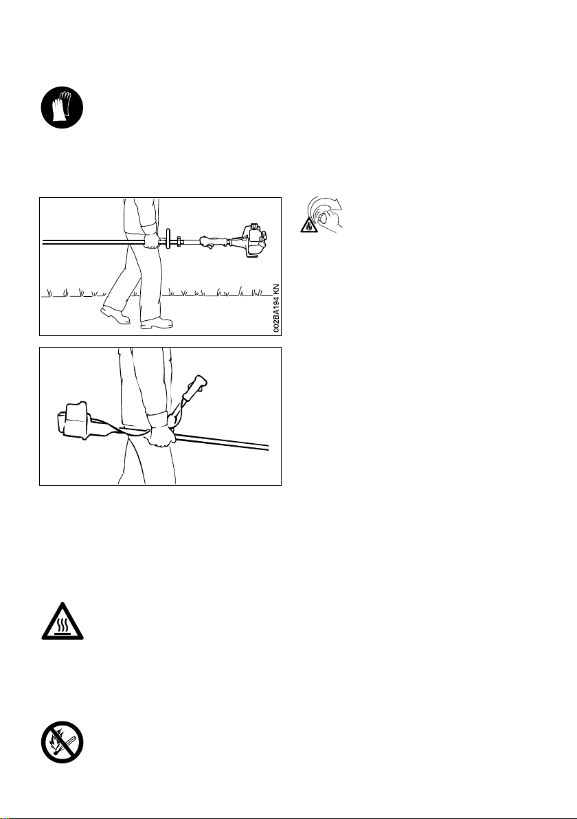
Operate your power tool so that it produces a
minimum of noise and emissions – do not run the
engine unnecessarily, accelerate the engine only
when working.
To reduce the risk of fire, do not smoke while
operating or standing near your power tool. Note
that combustible fuel vapor may escape from the
fuel system.
The dusts, vapor and smoke produced during
operation may be dangerous to health. If the
work area is very dusty or smoky, wear a respira‐
tor.
If your power tool is subjected to unusually high
loads for which it was not designed (e.g. heavy
impact or a fall), always check that it is in good
condition before continuing work – see also
"Before Starting".
Check the fuel system in particular for leaks and
make sure the safety devices are working prop‐
erly. Do not continue operating your power tool if
it is damaged. In case of doubt, consult your
servicing dealer.
Do not operate your power tool in the starting
throttle position – engine speed cannot be con‐
trolled in this position.
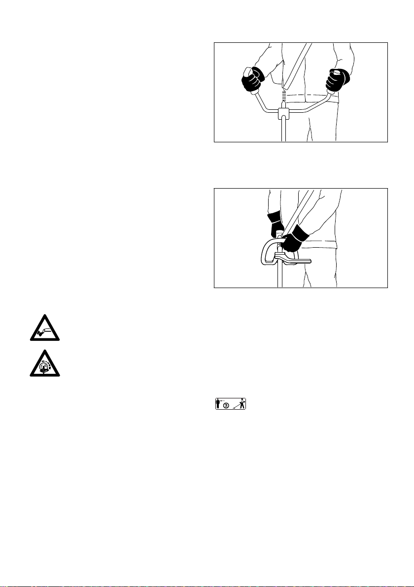
To reduce the risk of injury from
thrown objects, never operate the unit
without the proper deflector for the
type of cutting attachment being
used.
Inspect the work area: Stones, pieces
of metal or other solid objects may be
thrown more than 15 meters and
cause personal injury or damage the
cutting attachment and property (e.g.
parked vehicles, windows).
Special care must be taken when working in diffi‐
cult, over-grown terrain.
When cutting high scrub, under bushes and hed‐
ges: Keep cutting attachment at a minimum
height of 15 cm to avoid harming small animals.
Always shut off the engine before leaving the
machine unattended.
Check the cutting attachment at regular short
intervals during operation or immediately if there
is a noticeable change in cutting behavior:
–Turn off the engine. Hold the unit firmly and
wait for the cutting attachment to come to a
standstill.
–Check condition and tightness, look for cracks.
–Check sharpness.
–Replace damaged or dull cutting attachments
immediately, even if they have only superficial
cracks.
Clean grass and plant residue off the cutting
attachment mounting at regular intervals –
remove any build up of material from the cutting
attachment and deflector.
To reduce the risk of injury, shut off the engine
before replacing the cutting attachment.
The gearbox gets hot during opera‐
tion. To reduce the risk of burn injury,
do not touch the gearbox housing.
English 2 Safety Precautions and Working Techniques
6 0458-251-0121-B