Stihl FS 45 User manual

1. SafetyPrecautions 1
2. Introduction 2
3. Specifications 3
3.1 Engine 3
3.2 FuelSystem 3
3.3 IgnitionSystem 4
3.4 SpecialAccessories 4
3.4.1 ForUser 4
3.4.2 ForService 4
3.5 TighteningTorques 5
4. Clutch 6
4.1 Removingand
Installing 6
5. Engine 8
5.1 Replacing 8
5.2 ExhaustMuffler/
SparkArrestingScreen 9
5.3 LeakageTest 10
5.3.1 Preparations 10
5.3.2 PressureTest 11
5.3.3 VacuumTest 12
5.4 OilSeals 12
5.5 CylinderandPiston 14
5.5.1 Removal 14
5.5.2 Installation 15
5.6 PistonRing 16
5.7 Crankshaft/
BallBearings 16
6. IgnitionSystem 18
6.1 IgnitionModule 18
6.1.1 IgnitionTiming 18
6.1.2 Removingand
Installing 19
6.2 Flywheel 19
6.3 StopSwitch/
ShortCircuitWire/
GroundWire 20
7. RewindStarter 21
7.1 General 21
7.2 RewindSpring 22
7.2.1 Replacing 22
7.2.2 Tensioning 23
7.3 StarterRope/Starter
Grip(ElastoStart) 24
7.4 StarterCup 25
8. ThrottleControl 25
8.1 InterlockLever/
ThrottleTrigger 25
8.2 ThrottleCable 26
8.2.1 Replacing 26
8.2.2 AdjustingThrottle
Cable 27
9. FuelSystem 27
9.1 AirFilter 27
9.2 Carburetor 28
9.2.1 LeakageTest 28
9.2.2 Removingand
Installing 29
9.2.3 Adjusting 29
9.3 TankVent 30
9.4 FuelTank 31
9.5 PickupBody/
FuelHoses 31
10. Shaft 32
10.1 LoopHandle 32
10.2 DriveTube 32
10.3 FlexibleShaft 33
11. SpecialServicing
ToolsandAids 34
11.1 SpecialServicing
Tools 34
11.2 ServicingAids 36
1. SAFETY
1. SAFETY
Ifthebrushcutterisstartedup
inthecourseofrepairsor
maintenancework,observeall
localandcountry-specificsafety
regulationsaswellasthesafety
precautionsandwarningsinthe
owner’smanual.
Gasolineisanextremelyflamm-
ablefuelandcanbeexplosivein
certainconditions.
Improperhandlingmayresultin
burnsorotherseriousinjuries.
Warning!Donotsmokeorbring
anyfireorflamenearthefuel.All
workwithfuelmustbeperformed
outdoorsonly.Spilledfuelmustbe
wipedawayimmediately.
©1998AndreasStihlAG&Co.,Waiblingen
FS45
CONTENTS
FS45 1

This service manual contains
detailed descriptions of all the
repair and servicing procedures
specific to this power tool series.
There are separate handbooks
for servicing procedures for stand-
ardized parts and assemblies that
are installed in several STIHL
power tool models. Reference is
made to these handbooks in the
appropriate chapters in this
manual.
Servicing procedures on the
carburetor are described in the
"Carburetors" handbook.
You should make use of the
illustrated parts lists while carrying
out repair work. They show the
installed positions of the individual
components and assemblies.
Refer to the latest edition of the
relevant parts list to check the part
numbers of any replacement parts
needed. Parts lists on microfiche
and CD-ROM are always more up
to date than printed lists.
A fault on the machine may have
several causes. To help locate the
fault, consult the troubleshooting
charts for all assemblies in the
"Standard Repairs, Troubleshoo-
ting" handbook.
Refer to the "Technical Informa-
tion" bulletins for engineering
changes which have been intro-
duced since publication of this
service manual. Technical informa-
tion bulletins also supplement the
parts list until a revised edition is
issued.
Special servicing tools mentioned
in the descriptions are listed in the
last chapter of this manual.
Use the part numbers to identify
the tools in the "STIHL Special
Tools" manual.
The manual lists all special
servicing tools currently available
from STIHL.
Symbols are included in the text
and pictures for greater clarity.
The meanings are as follows:
In the descriptions:
•= Actiontobetakenas
shown in the illustration
(above the text)
- = Action to be taken that
is not shown in the
illustration
(above the text)
In the illustrations:
= Pointer
= Direction of movement
Service manuals and all technical
information bulletins describing
engineering changes are intended
exclusively for the use of STIHL
servicing dealers. They must not
be passed to third parties.
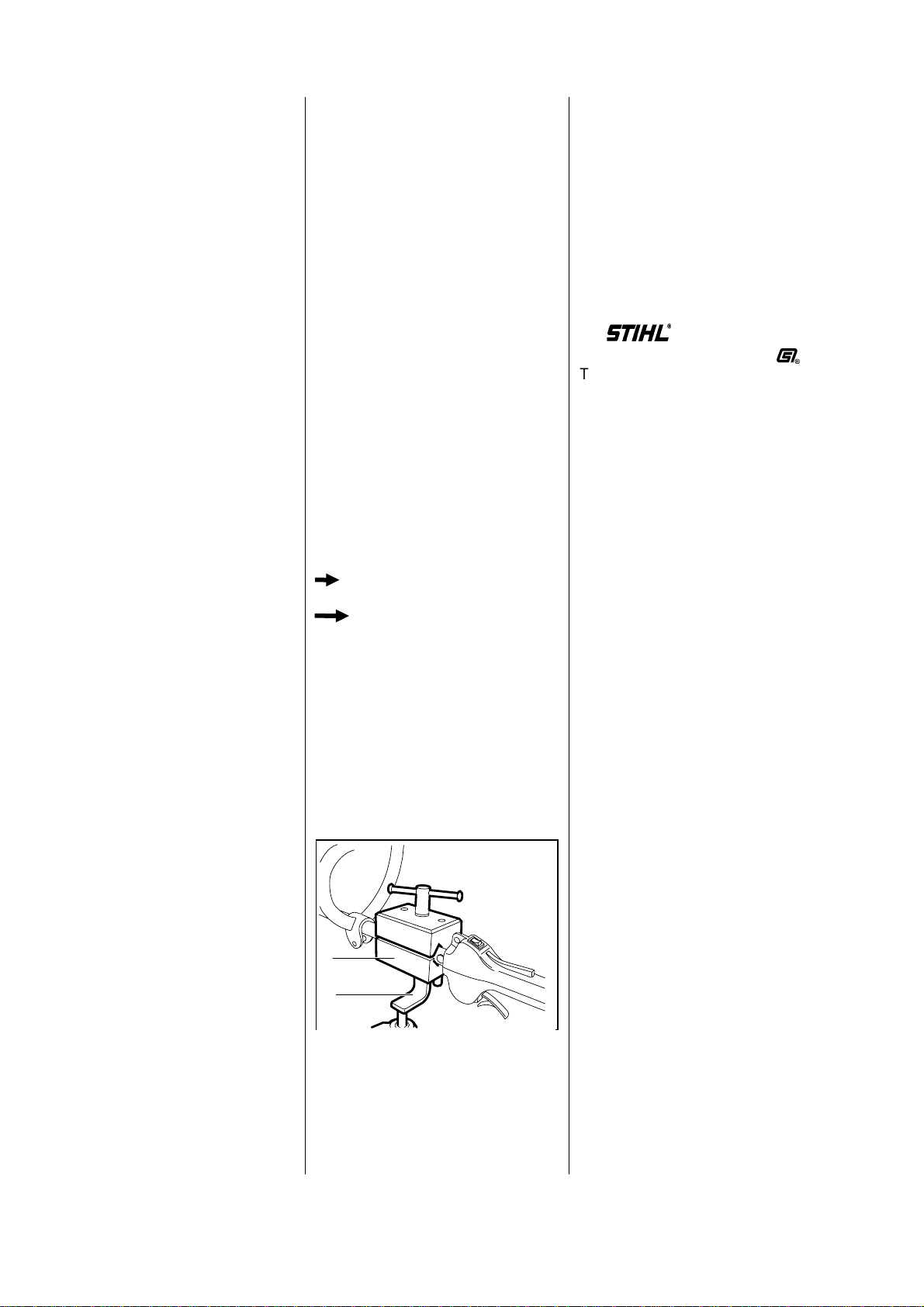
Servicing and repairs are made
considerably easier if the machine
is mounted on assembly standard
(2) 5910 890 3100 with the aid of
clamp (1) 5910 890 8800.
Secure the clamp to the assembly
stand with two washers and two
M8 nuts.
The complete unit can then be
swivelled to the best position for
the ongoing repair and this leaves
both hands free.
Always use original STIHL
replacement parts.
They can be identified by the
STIHL part number,
the logo
and the STIHL parts symbol
(
The symbol may appear alone on
small parts.
2. INTRODUCTION
VA
232RA001
2
1
2FS 45

3.1 Engine STIHL single-cylinder two-stroke engine with special impregnated
cylinder bore
Displacement: 27.2 cm3(1.66 cu.in)
Bore: 34mm(1.34in)
Stroke: 30mm(1.18in)
Engine power to ISO 7293: 0.75 kW (1 bhp)
at 7000 rpm
Max. permissible engine speed
without cutting tool
(cut-off speed): 9,500 ±800 rpm
Idle speed: 2,800 ±300 rpm
Bearings: Crankshaft supported in heavy-
duty ball bearings, needle cages
on small and big ends
Piston pin diameter: Ø 8 mm (0.31 in)
Rewind starter: Pawl engagement
Pawls: Single pawl system
Reserve pull on rope rotor: min. 1/2 turn
Starter rope: Ø 3 mm (0.12 in) dia.,
800 mm (31.5 in)
Clutch: Centrifugal clutch without linings
Clutch engages at: 3,800 rpm
Crankcase leakage test
at gauge pressure: pü = 0.5 bar (7.25 psi)
under vacuum: pu = 0.5 bar (7.25 psi)
3.2 Fuel System Carburetor: Diaphragm carburetor
Carburetor leakage test
at gauge pressure: pü = 0.8 bar (11.6 psi)
Operation of tank vent
at gauge pressure: pü ≤ 0.3 bar (4.35 psi)
under vacuum: pu ≤ 0.05 bar (0.725 psi)
Fuel tank capacity: 0.30 l (0.63 US pt)
Octane rating: min. 90 RON (US/CAN: pump
octane min. 87)
Fuel mixture: Regular brand-name gasoline
and two-stroke engine oil
Mix ratio: 50:1 with STIHL two-stroke
engine oil
25:1 with other brand-name
two-stroke, air-cooled engine oils
Air filter: Felt element
3. SPECIFICATIONS
FS 45 3

3.3 Ignition System Type: Electronic magneto
ignition (breakerless)
with integral trigger unit
Air gap: 0.2 - 0.45 mm (0.008 - 0.018 in)
Spark plug (suppressed): Bosch WSR 6F,
NGK BPMR 7 A,
Champion RCJ 6Y
Electrode gap: 0.5 mm (0.020 in)
3.4 Special Accessories
3.4.1 For User Shoulder strap
Safety glasses
STIHL ElastoStart
(starter rope with grip) 0000 190 3400
STIHL gear lubricant for brushcutters
- 80g/3oz tube 0781 120 1117
- 225g/8oz tube 0781 120 1118
3.4.2 For Service Carburetor parts kit 4227 007 1060
Gasket kit 4140 007 1050
4FS 45

DG and P (Plastoform) screws are used in polymer and lightmetal components. These screws form a
permanent thread when they are installed for the first time. They can be removed and installed as often
as necessary without detrimentally affecting the strength of the screwed assembly, providing the specified
tightening torque is observed. For this reason it is essential to use a torque wrench.
Fastener Thread For component Torque Remarks
size Nm lbf.ft
Plastoform screw P6x14 Line limiting blade/deflector 2.5 1.8
Nut M5 Filter housing/carburetor/
spacer flange 3.5 2.6
Pan head screw 8-32 Clutch drum/crankshaft 4.0 3.0
Spline screw IS-DG5x24 Fixing screw for clutch drum
in engine housing 4.5 3.3 1)
Spline screw IS-DG5x60 Engine pan/crankcase/cylinder 9.0 6.6 2)
3/8" Clutch carrier 17.0 12.5
Spline screw IS-DG5x24 Engine housing/shroud 4.5 3.3 1)
Spline screw IS-DG5x24 Engine housing/crankcase 9.0 6.6 1)
Spline screw IS-DG5x60 Muffler/cylinder 9.0 6.6 2)
M14x1.25 Stub/muffler 15.0 11.0 3)
Pan head screw M5x8 Drive tube/guide 8.0 5.9
Spline screw IS-DG5x12 Drive tube/engine housing 2.0 1.5 1)
Spline screw IS-DG5x20 Starter cover/crankcase 6.0 4.4 1)
Spline screw IS-DG5x20 Starter cover/engine pan 6.0 4.4 1)
M8 Starter cup 17.0 12.5
Spline screw IS-DG5x24 Spacer flange/cylinder 6.0 4.4 2)
M14x1.25 Spark plug 20.0 15.0
Spline screw IS-DG4x20 Ignition module/cylinder 4.5 3.3 2)
Spline screw IS-DG5x24 Bracket/fuel tank 4.0 3.0 1)
Use the following procedure to fit a DG or P screw in an existing thread:
– Place the DG or P screw in the hole and rotate it counterclockwise until it drops down slightly.
– Tighten the screw clockwise to the specified torque.
This procedure ensures that the screw engages properly in the existing thread and does not form a new thread
and weaken the assembly.
Note: Power screwdriver speed settings for polymer: Plastoform screws max. 600 rpm,
DG screws max. 500 rpm
Important: Do not confuse screws with and without underhead locking teeth.
1) With locking teeth
2) Without locking teeth
3) Install with sealant
3.5 Tightening Torques
FS 45 5

Removing
Troubleshootingchart-see
"StandardRepairs,Trouble-
shooting"handbook.
-Removethedrivetube-
see10.2.
-Removethefueltank-see9.4.
•Takeoutscrewsatfrontendof
shroud.
•Takeoutscrewsatrearendof
shroud.
•Liftawaytheshroud.
•Disconnecttheshortcircuit
wire(1)andgroundwire(2)
fromtheignitionmodule.
•Removethrottlecable(1)nipple
fromslottedpin(2)onthrottle
lever.
•Takethrottlecableoutof
tensioner.
•Takeoutthescrews(1).
-Removetheenginehousing.
Note:Removescrew(2)onlyif
damaged.Tightendownnew
screwto4.5Nm(3.3lbf.ft).
-Pulloffthesparkplugboot.
-Unscrewthesparkplug.
•Fitlockingstrip(1)
42218935900insparkplug
hole.
4.CLUTCH
4.1RemovingandInstalling
VA
232RA004
VA
232RA007
VA
232RA002
VA
232RA005
2
1
VA
232RA008
21
1
VA
232RA003
VA
232RA006
2
1
VA
232RA009
1
6FS45

•Use socket (1) 0812 540 1112 to
unscrew clutch drum screw.
- Remove clutch drum.
•Examine the clutch drum. It must
not be scored or worn.
Important: If there are signs
of serious wear on the inside
diameter, fit a new clutch drum.
•Push pins of wrench (1)
4130 890 3600 into semicircular
recesses in the clutch.
•Unscrew the clutch.
•If necessary, remove washer (1)
and spacer sleeve (2) from the
crankshaft.
Note: Clutch shoes, carrier
and springs are supplied as
a complete assembly (clutch).
Clutch springs can be replaced.
•Push the carrier (1) out of the
clutch shoes (2).
•Detach the clutch springs (3).
Important: Clutch springs must
always be replaced in pairs.
Installing
•Attach springs to the clutch
shoes exactly as shown in the
illustration.
Important: They must not project
sideways.
•Hold carrier at an angle. Pull
clutch shoes slightly apart. Press
the carrier into position.
- Refit the spacer sleeve and
washer, if removed, on the
crankshaft stub.
VA
232RA010
1
VA
232RA013
12
VA
232RA015
VA
232RA011
VA
235RA014
2
3
2
1
VA
232RA016
VA
232RA012
1
FS 45 7

•Fittheclutchclockwisesothat
thearrowandtheword"OFF"
faceoutwards.
•Fitwrench(1)41308903600
andtightendownclutchto17.0
Nm(12.5lbf.ft).
Assembleallotherpartsinthe
reversesequence.
•Usesocket(1)08125401112to
tightendownclutchdrumscrew
to4.0Nm(3.0lbf.ft).
-Removetheclutch-see4.1.
•Takeoutthescrews.
-Removethemuffler.
•Removethegasket.
•Pulloffthesparkplugboot(1).
•Takeoutthescrews(2).
•Removetheignitionmodule(3).
•Freeofftheflywheelbylightly
tappingtheendofthecrankshaft
stubwitharubbermallet.
-Pullofftheflywheel.
-Removethefiltercoverand
takeoutthefeltfilterelement-
see9.1.
•Unscrewthenuts(1).
•Pulloffthefilterhousing(2)and
carburetor(3).
•Removethegasket.
VA
232RA017
VA
232RA020
VA
232RA023
VA
232RA018
1
VA
232RA021
VA
232RA024
2
3
1
VA
232RA019
1
VA
232RA022
1
2
3
2
VA
232RA025
5. ENGINE
5.1Replacing
8FS45

•Takeoutthescrews.
-Removethespacerflangewith
tensioner.
•Removethegasket.
-Unscrewthesparkplug
andfitthelockingstrip
42218935900.
•Unscrewthestartercupfromthe
crankshaft.
Assembleinthereversesequence.
-Fitnewgaskets.
•Insertcarburetormounting
screwsinthespacerflange.
-Tightenscrewstospecified
torque-see3.5.
-Secureterminalforground
wiretoupperignition
modulemountingscrew.
-Adjustignitionmodule
(airgap),see6.1.
Troubleshootingchart-see
"StandardRepairs,Trouble-
shooting"handbook.
-Removethestartercup-
see7.2.1.
Sparkarrestingscreen
•Unscrewstubwithspark
arrestingscreen.
-Cleanthesparkarresting
screen,
installanewstubifnecessary.
-Cleanthethreadonthestuband
coatwithsealant-see11.2.
Important:Followmanufacturer’s
instructions.
-Fitthestubandtightendownto
15Nm(11lbf.ft).
5.2ExhaustMuffler/
SparkArrestingScreen
VA
232RA026
VA
232RA029
VA
232RA027
VA
232RA030
VA
232RA028
FS45 9

•Takeoutthescrews.
-Removethemuffler.
•Removethegasket.
Installinthereversesequence.
-Useanewgasket.
-Tightenscrewsto9.0Nm
(6.6lbf.ft).
Defectiveoilsealsandgasketsor
cracksincastingsaretheusual
causesofleaks.Suchfaultsallow
supplementaryairtoenterthe
engineandthusupsetthefuel-air
mixture.
Thismakesadjustmentofthe
prescribedidlespeeddifficult,if
notimpossible.
Moreover,thetransitionfromidle
speedtopartorfullthrottleisnot
smooth.
Thecrankcasecanbechecked
thoroughlyforleakswiththe
carburetorandcrankcasetester
andthevacuumpump.
-Removetheshroud-see4.1.
-Removethecarburetor-
see9.2.2.
-Setthepistontotopdeadcenter
(T.D.C.).Thiscanbechecked
throughtheinletport.
-Makesurethesparkplugis
properlytighteneddown.
•Fitanewgasketonspacer
flange.
•Fitthetestflange(1)
11288504200onthecarburetor
mountingstuds.
•Fitnuts(2)andtightendownto
3.5Nm(2.6lbf.ft).
5.3LeakageTest 5.3.1Preparations
VA
232RA031
VA
232RA113
VA
232RA032
VA
232RA033
1
22
10 FS45

-Slackenoffthemufflermounting
screwshalf-way.
•Slidethesealingplate(1)
00008558106betweenthe
gasketandcylinder.Retighten
thescrewsmoderately.
Note:Thesealingplatemust
completelyfillthespacebetween
thetwoscrews.
-Carryoutpreparations-
see5.3.1.
•Connectpressurehoseoftester
11068502905tonippleontest
flange.
•Closetheventscrew(1)on
therubberbulb.
-Userubberbulbtopumpairinto
theengineuntilthegauge
indicatesapressureof0.5bar
(7.25psi).Ifthispressure
remainsconstantforatleast
20seconds,thecrankcaseis
airtight.
•However,iftheindicated
pres-suredrops,theleakmust
belocatedandthefaultypart
replaced.
Note:Tofindtheleak,coatthe
suspectareawithoiland
pressurizethecrankcaseagain.
Bubbleswillappearifaleakexists.
-Repeatthepressuretest.
-Carryoutthevacuumtest-
see5.3.3.
-Afterfinishingthetest,openthe
ventscrewanddisconnectthe
hose.
-Removethetestflange.
-Slackenoffthemufflermounting
screws.
-Pulloutthesealingplateand
tightendownthescrewsto
9.0Nm(6.6lbf.ft).
-Installthecarburetor-see9.2.2.
-Fittheshroud.
5.3.2PressureTest
VA
232RA034
1
VA
232RA035
11
143RA046
232RA036
0
0,2
0,4 0,6
0,8
1,0
VA
FS45 11

Oilsealstendtofailwhen
subjectedtoavacuum,i.e.the
sealinglipliftsawayfromthe
crankshaftduringthepiston’s
inductionstrokebecausethere
isnointernalcounterpressure.
Anadditionaltestcanbecarried
outwiththevacuumpumpto
detectthiskindoffault.
-Carryoutpreparations-
see5.3.1.
•Connectthesuctionhoseof
vacuumpump00008503501
totestflangenipple.
•Closeventscrew(1)on
pumpcylinder.
•Operatelever(2)untilthe
gauge(3)indicatesavacuumof
0.5bar(7.25psi).
Note:Ifthevacuumreading
remainsconstant,orrisestono
morethan0.3bar(4.25psi)within
20seconds,itcanbeassumed
thattheoilsealsareingood
condition.
However,ifthepressurecontinues
torise(reducedvacuuminthe
crankcase),theoilsealsmustbe
replaced.
-Afterfinishingthetest,openthe
ventscrewanddisconnectthe
hose.
-Removethetestflange.
-Slackenoffthemufflerscrews.
-Removethesealingplateand
tightenscrewsto9.0Nm
(6.6lbf.ft)festziehen.
-Installthecarburetor-see9.2.2.
-Fittheshroud.
Itisnotnecessarytodisassemble
thecompleteenginetoreplacethe
oilseals.
Starterside:
-Removethestartercup-see7.4.
-Removetheenginehousing-
see4.1.
•Applythepuller(1)
59108904400(withNo.3.1
jaws00008933706).
-Tensionthearms.
-Pullouttheoilseal.
Important:Takecarenotto
damagecrankshaftstub.
-Cleansealingsurfacewitha
standardsolvent-baseddegrea-
santcontainingnochlorinatedor
halogenatedhydrocarbons-
see 11.2.
-Lubricatesealinglipsofoilseal
withgrease-see 11.2.
5.3.3VacuumTest 5.4OilRings
VA
232RA038
1
VA
232RA037
1
2
3
VA
232RA035
12 FS45

•Slipinstallingsleeve(1)
11298934600overtheend
ofthecrankshaft.
•Slidetheoilseal(1),openside
facingthecrankcase,overthe
endofthecrankshaft.
•Usethepresssleeve(2)
11148934601topressitfully
home.
-Fittheenginehousing.
-Installthestartercup.
Clutchside:
-Removetheflywheel-see6.2.
•Applythepuller(1)
59108904400(withNo.3.1
jaws00008933706).
-Tensionthearms.
-Pullouttheoilseal.
Important:Takecarenotto
damagecrankshaftstub.
-Cleansealingsurfacewitha
standardsolvent-baseddegrea-
santcontainingnochlorinated
orhalogenatedhydrocarbons-
see11.2.
-Lubricatesealinglipsofoilseal
withgrease-see11.2.
•Slidetheoilseal(1),openside
facingthecrankcase,overthe
installingsleeve.
•Usethepresssleeve(2)
11208932400topressitfully
home.
-Fittheflywheel.
VA
232RA039
1
VA
232RA041
1
VA
232RA040
2
1
VA
232RA042
2
1
FS45 13

Alwayscheckand,ifnecessary,
repairthefuelsystem,carburetor,
airfilterandignitionsystembefore
lookingforfaultsontheengine.
Troubleshootingchart-see
"StandardRepairs,Trouble-
shooting"handbook.
-Removethemuffler,ignition
module
andspacerflange-see5.1.
-Unscrewthesparkplug.
•Fitjaws(1)00008933700
withNo.2profileonpuller(2)
59108904400.
•Fitthescrewbush(3)
11088934500onthespindle.
•Toensurethatthecrankcase
andenginepandonotcome
apartwhenthecylinderis
removed,holdbothparts
togetherwiththepuller.
•Unscrewthecylinderbase
screws.
-Clampthepullerinavise.
-Pullthecylinderoffthepiston.
-Inspectthecylinderandreplace
itifnecessary.
-Ifanewcylinderhastobe
installed,alwaysfitthematching
piston.Newcylindersareonly
availablewithpiston.
-Removethecylindergasket.
•Atthestartercupside,takethe
snapring(B8x0.7)outofthe
groove.
Note:Thehooklesssnapringat
theflywheelsideremainsinthe
groove.
•Nowusethe7mm(1/4")diadrift
topushthepistonpin(1)outof
thepiston.
Note:Ifthepistonpinisstuck,tap
theendofthedriftlightlywitha
hammerifnecessary.Holdthe
pistonsteadyduringthisprocess
toensurethatnojoltsaretrans-
mittedtotheconnectingrod.
-Removepistonfromthe
connectingrod.
-Inspectneedlecafeandreplace
crankshaftifnecessary-see5.7.
-Inspectpistonringandreplaceif
necessary-see5.6.
5.5 CylinderandPiston
5.5.1Removing
VA
232RA114
VA
232RA117
VA
232RA116
VA
232RA115
VA
232RA118
131
2
14 FS45

- Thoroughly clean the gasket
seating surface.
- Lubricate the needle cage in the
connecting rod with oil.
•To simplify assembly, heat the
piston and slip it over the
connecting rod.
•Installed position of piston:
1 = Marking = exhaust side
2 = Flywheel
•Fit the piston pin in position and
use assembly drift (1)
1114 893 4700 to push it up to
stop against the hookless snap
ring (the pin slides home easily if
the piston is hot).
- Fit snap ring (B8x0.7) so that its
gap is on the piston’s vertical
axis (pointing either up or down).
•Fit new cylinder gasket.
•Lubricate piston and piston
ring with oil. Rest piston (1) on
wooden assembly block (2)
1108 893 4800.
•Positionthepistonringsothat
the radii at the ring gap meet at
thefixingpininthepistongroove
when the rings are compressed.
•Use the clamping strap (1)
0000 893 2600 to compress the
piston ring around the piston.
- Check that the piston ring is
correctly positioned.
- Lubricate the inside of the
cylinder with oil and line it up
so that it is positioned as it will
be in the installed condition.
It is important to observe this
point as the piston ring might
otherwise break.
5.5.2 Installing
VA
1
232RA119
2
VA
232RA123
VA
232RA121
VA
232RA124
1
VA
232RA120
1
VA
232RA122
1
2
FS 45 15

•Slidethecylinderoverthepiston
-theclampingstrapispushed
downwardasthepistonring
slipsintothecylinder.
-Removetheclampingstrap
andwoodenassemblyblock.
-Lineupthecylinderandgasket.
•Usesocket(1)08125422104
totightendowncylinderbase
screwsto9.0Nm(6.6lbf.ft).
Assembleallotherpartsinthe
reversesequence.
-Removethepiston-see5.5.1.
Note:Thepistonmustbe
removedtomakesurethatno
residuecanfallintothecrankcase
wheninstallingthepistonringand
cleaningitsgroove.
-Removeringfrompiston.
•Useapieceofoldpistonring
toscrapethegrooveclean.
•Installthenewpistonringinthe
groovesothattheradii(1)face
thefixingpin(2).
-Installthepiston-see5.5.2.
-Removethecylinder-see5.5.1.
•Removetheflywheel(1),starter
cup(2)andpiston(3).
•Removethepuller(4).
•Pulltheenginepanoffthe
crankcase.
•Liftcrankshaftoutofcrankcase.
-Inspectballbearingsandoil
sealsandreplaceifnecessary.
5.6 PistonRing 5.7 Crankshaft/BallBearings
VA
232RA125
VA
232RA129
2
1
4
3
VA
232RA127
VA
232RA130
VA
232RA126
1
VA
232RA128
2
1 1
VA
232RA131
16 FS45

•Thecrankshaft(1),connecting
rod(2)andneedlebearing
formaninseparableunit.
Itmustalwaysbereplacedasa
completeunit.
-Whenfittingareplacement
crankshaftalwaysinstallnewoil
sealsandballbearings.
•Pullofftheoilseals(1)andball
bearings(2).
-Removethewashers.
•Slipwashers(1)ontorightand
leftcrankshaftstubs.
•Heatballbearings(2)toapprox.
50°C(120°F)andpushthem
homeasfarasstop.
-Lubricatesealinglipsofoilseals
withgrease-see11.2.
•Slidetheoilseals,opensides
facingtheballbearings,over
theendsofthecrankshaft.
-Thoroughlycleanthesealing
facesonthecrankcaseand
enginepantoremovealltraces
ofsealant.
•Placecrankshaftinthecrank-
casesothattheconnectingrod
(1)pointstothecylinderside
andtheshortcrankshaftstub(2)
isatthewideside(arrow)ofthe
crankcase.
•Applyathinbeadofsealantto
theenginepan’smatingface-
see11.2.
Important:Followmanufacturer’s
instructions.
-Fittheenginepanandclampit
tothecrankcasewiththepuller-
see5.5.1.
Assembleallotherpartsinthe
reversesequence.
VA
232RA132
1
2
VA
232RA134
22 1
VA
232RA135
VA
232RA137
VA
232RA133
21 12
VA
232RA136
1 2
FS45 17

Warning! Exercise extreme
caution when carrying out
maintenance and repair work on
the ignition system. The high
voltages which occur can cause
serious or even fatal accidents!
Troubleshooting on the ignition
system should always begin at
the spark plug. See "Standard
Repairs, Troubleshooting"
handbook.
Note: The electronic (breakerless)
ignition system basically consists
of an ignition module (1) and
flywheel (2).
The ignition module accommoda-
tes all the components required to
control ignition timing.
There are two electrical connec-
tions on the coil body:
1. the high voltage output (1) with
ignition lead (2)
2. the connector tag (3) for the
short circuit wire
Accurate testing of the ignition
module is only possible with
sophisticated test equipment.
For this reason it is only necessary
to carry out a spark test in the
work-shop. A new ignition module
must be installed if no ignition
spark is obtained (after checking
that wiring and stop switch are in
good condition).
Ignition timing is not adjustable.
Since there is no mechanical wear
in these systems, ignition timing
cannot get out of adjustment.
However, an internal fault in the
circuit can alter the switching point
in such a way that a spark test will
stillshowthesystemtobeinorder
although timing is outside the
permissible tolerance. This will
impair engine starting and running
behavior.
6. IGNITION SYSTEM 6.1 Ignition Module 6.1.1 Ignition Timing
VA
232RA043
2
1
VA
232RA044
3
2
1
18 FS 45

-Removetheshroud-see4.1.
•Disconnectshortcircuitwire(1)
andgroundwire(2)fromthe
ignitionmodule.
-Pullbootoffthesparkplug.
•Takeoutthescrews.
-Removetheignitionmodule.
Note:Theignitionleadismolded
totheignitionmodule.
-Placetheignitionmodulein
position,insertthescrewsbut
donottightenthemdownyet.
•Secureconnectortag(1)for
shortcircuitwirewithupper
screw.
•Slidethesettinggauge(1)
11278906400betweenthe
armsoftheignitionmoduleand
theflywheelmagnetpoles.
-Presstheignitionmodule
againsttheflywheelandtighten
downthemountingscrewstoa
torqueof4.5Nm(3.3lbf.ft).
Assembleallotherpartsinthe
reversesequence.
Removingtheflywheel:
-Removetheclutch-see4.1.
•Freeofftheflywheelbylightly
tappingtheendofthecrankshaft
stubwitharubbermallet.
-Pullofftheflywheel.
Inspecttheconditionofthe
flywheel(1)andmagnetpoles(2).
Ifyoufindanydamage(cracks
etc.),fitanewflywheel.
6.1.2RemovingandInstalling 6.2Flywheel
VA
232RA005
2
1
VA
232RA046
2
1
232RA047
VA
VA
232RA045
VA
232RA048
1
2
FS45 19

Installingtheflywheel:
Important:Cleanthestubofthe
crankshaftandtheflywheelhub
borewithastandardcommercial,
solvent-baseddegreasant
containingnochlorinatedorhalo-
genatedhydrocarbons-see11.2.
-Fittheflywheel.
Note:Checkpositionofslot.
-Installtheclutch-see4.1.
-Pulllockingstripoutofcylinder.
-Fitsparkplugandtorquedown
to
20Nm(15lbf.ft).
Important:Ifthesparkplug
comeswithaseparateterminal
nut,alwaysfitthenutonthe
threadandtightenitdown
securely.
-Fitthebootonthesparkplug.
Stopswitch
-Removetheshroud-see4.1.
•Pressdowntheinterlock
lever(1).
•Pullthebase(2)outofthe
enginehousing.
•Unhookthewires(1)fromthe
retainer(2).
•Easethestopswitch(3)outof
thebase.
•Disconnecttheshortcircuitwire
andgroundwirefromthestop
switch.
Installinthereversesequence.
-Pressdowntheinterlocklever.
•Fitthebasesothatits
pegs(1)engagetheholes(2).
6.3 StopSwitch/ShortCircuitWire/
GroundWire
VA
250RA008
VA
232RA049
21
VA
232RA051
VA
232RA052
11
2
VA
232RA050
3
1
2
20 FS45
Other manuals for FS 45
5
Table of contents
Other Stihl Brush Cutter manuals
Popular Brush Cutter manuals by other brands

BROWN
BROWN Brush Ox 2600 Series Owner's/operator's manual

Echo
Echo SRM-210 - 02-04 Operator's manual

Brush Wolf
Brush Wolf 4200 Instruction & maintenance manual

O-Mac
O-Mac MS 2700 Operator's manual

Z.I.P.P.ER MASCHINEN
Z.I.P.P.ER MASCHINEN ZI-MOS145JAK user manual

Powersmart
Powersmart PS4531 instruction manual

Sun Seeker
Sun Seeker BCI 52 Operator's manual

Craftsman
Craftsman 358.79828 Operator's manual

Stiga
Stiga B 26 J Operator's manual

Elem Garden Technic
Elem Garden Technic DCBT43D-2S20FR instruction manual

Hitachi
Hitachi CG40EASP Handling instructions

Global garden products
Global garden products B 26 J Operator's manual