adjustments or repairs. STIHL recommends you
have this work done by a STIHL servicing dealer.
Take special care in slippery conditions – damp,
snow, ice, on slopes or uneven ground.
Watch out for obstacles: tree stumps, roots – risk
of tripping or stumbling!
Only work while standing on the ground, never
on a ladder or mobile elevated work platform.
Be particularly alert and cautious when wearing
hearing protection because your ability to hear
warnings (shouts, alarms, etc.) is restricted.
Take breaks when you start getting tired or feel‐
ing fatigue – risk of accidents!
Work calmly and carefully – in daylight conditions
and only when visibility is good. Proceed with
caution, do not put others in danger.
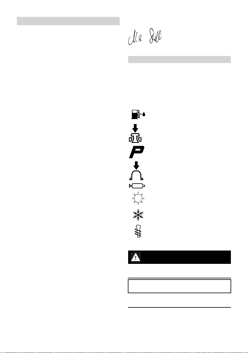
As soon as the engine is running, the
power machine generates toxic
exhaust gas.As soon as the engine is
running, the power machine gener‐
ates toxic exhaust gas. These gases
may be odorless and invisible and
may contain unburned hydrocarbons
and benzene. Never run the engine
indoors or in poorly ventilated loca‐
tions, even if your model is equipped
with a catalytic converter.
To reduce the risk of serious or fatal injury from
breathing toxic fumes, ensure proper ventilation
when working in trenches, hollows or other con‐
fined locations.
Stop work immediately if you start suffering from
nausea, headaches, impaired vision (e.g. your
field of vision gets smaller), impaired hearing,
dizziness, or impaired concentration – these
symptoms may possibly be the result of too-high
exhaust gas concentration – Risk of accidents!
Operate your power tool so that it produces a
minimum of noise and emissions – do not run the
engine unnecessarily, accelerate the engine only
when working.
To reduce the risk of fire, do not smoke while
operating or standing near your power tool. Com‐
bustible fuel vapor may escape from the fuel sys‐
tem.
Dust, fumes and smoke produced while working
may be hazardous to your health. Wear respira‐
tory protection in case of heavy dust or smoke
emission.
If your power tool is subjected to unusually high
loads for which it was not designed (e.g. heavy
impact or a fall), always check that it is in good
condition before continuing work – see also
"Before Starting".
Check in particular that the fuel system has no
leaks and the safety equipment is fully operative.
Never use a power tool that is no longer safe to
operate. In case of doubt, contact a dealer.
Do not operate your power tool in the starting
throttle position – engine speed cannot be con‐
trolled in this position.
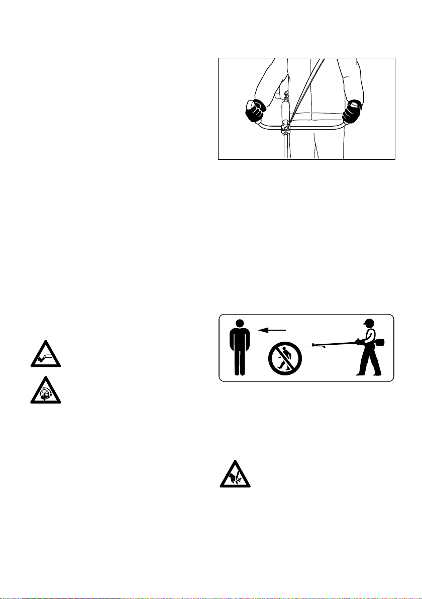
To reduce the risk of injury from
thrown objects, never operate the unit
without the proper deflector for the
type of cutting attachment being
used.
Check the work site – rocks, metal
objects etc. may be caught up and
ejected – possibly over a distance of
15 m – risk of injury! – They can also
damage the cutting attachment and
other property (e. g. parking vehicles,
windows).
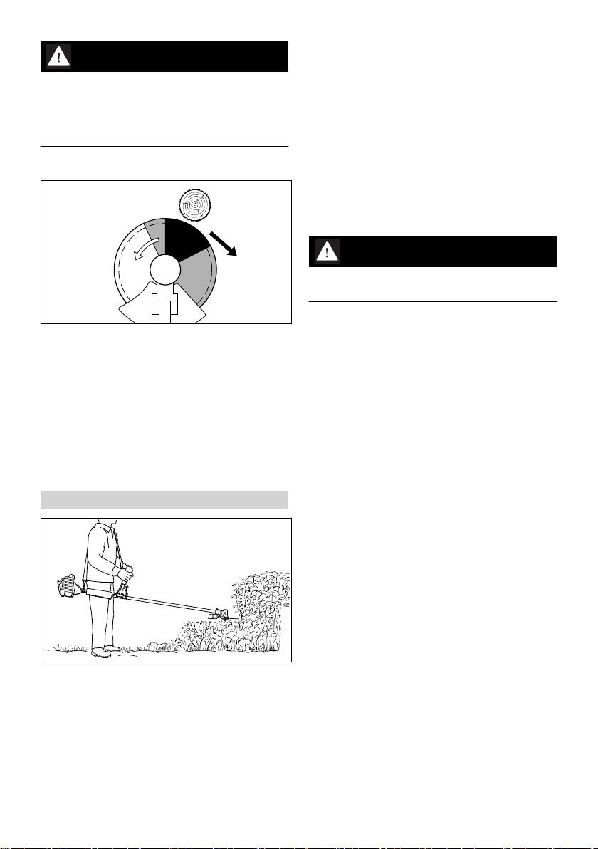
Be particularly careful when working on difficult,
densely grown terrain.
When mowing in high shrubbery, under shrub‐
bery and hedges: Hold the cutting tool at a work‐
ing height of at least 15 cm – avoid risks to ani‐
mals.
Before you leave the machine: Shut the engine
off.
Examine the cutting attachment periodically at
short intervals and as soon as you note any
noticeable changes:
–Stop the engine, hold the machine securely,
allow the cutting attachment to come to a stop
–Check condition and secure fitting; watch out
for cracks
–Ensure that the cutting blades are sharp
–Replace damaged or dull cutting attachments
immediately, even if they have only superficial
cracks
Clean grass and plant residue off the cutting
attachment mounting at regular intervals –
remove any build up of material from the cutting
attachment and deflector.
To reduce the risk of injury, shut off the engine
before replacing the cutting attachment.
The gearbox gets hot during opera‐
tion. Never touch the gearbox – risk
of burns!
English 2 Safety Precautions and Working Techniques
6 0458-262-0121-C