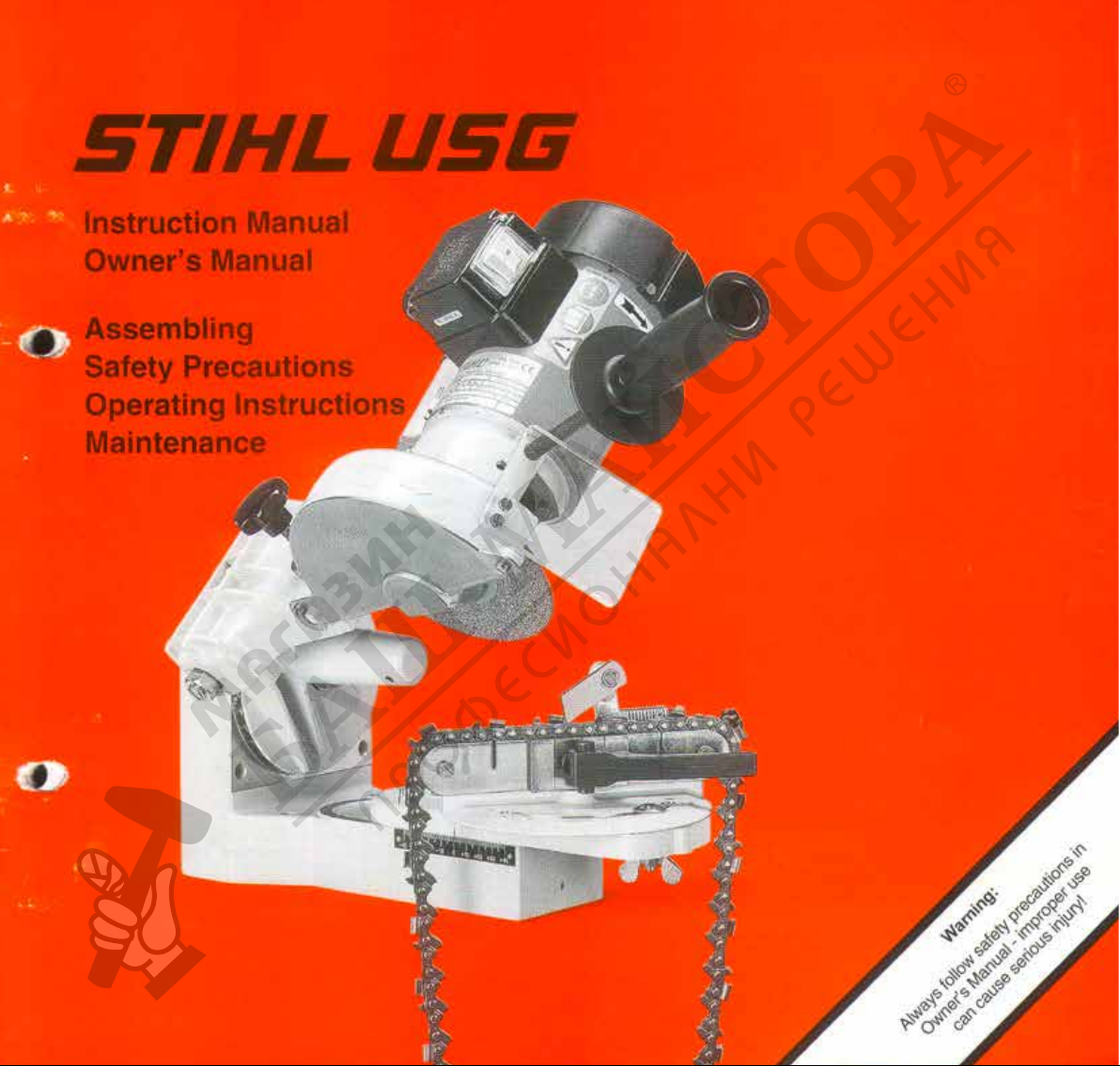
Stihl USG User manual


1USG
English
BA_SE_025_002_01_06.fmPrinted on chlorine-free paper.
Printing inks contain vegetable oils; paper can be recycled.
© ANDREAS STIHL AG & Co. KG, 2004
0458 523 0121. M0,5. C4. T. Printed in Germany
STIHl
Contents
Guide to Using this Manual .............. 2
Safety Precautions ........................... 3
Applications ...................................... 4
Mounting the Tool ............................. 4
Selecting the Grinding Wheel ........... 6
Mounting the Grinding Wheel ........... 7
Test Run ........................................... 8
Dressing the Grinding Wheel ............ 8
Scales ............................................... 8
Setup for Sharpening Saw Chain ..... 9
Sharpening Procedure ................... 15
Lowering Depth Gauges ................. 17
Setup for Sharpening
Hedge Trimmer Blades ................... 19
Sharpening
Hedge Trimmer Blades ................... 24
Preparations for Sharpening
Circular Saw Blade ......................... 27
Sharpening Circular Saw Blade ...... 31
Maintenance Chart ......................... 32
Minimize Wear and
Avoid Damage ................................ 33
Main Parts of Sharpener ................. 34
Specifications ................................. 35
Special Accessories ....................... 35
Maintenance and Repairs ............... 35
Certificate of Conformity ................. 36
Quality Certification ........................ 36
Dear Customer,
Thank you for choosing a quality
engineered STIHL product.
This machine has been built using
modern production techniques and
comprehensive quality assurance.
Every effort has been made to ensure
your satisfaction and troublefree use
of the machine.
Please contact your dealer or our
sales company if you have any
queries concerning your machine.
Hans Peter Stihl

2
English
USG
Pictograms
All the pictograms attached to the
machine are shown and explained in
this manual.
The operating and handling instructions
are supported by illustrations.
Symbols in text
The individual steps or procedures
described in the manual may be marked
in different ways:
:Step or procedure without direct
reference to an illustration.
Description of step or procedure that
refers directly to the illustration and
contains item numbers that appear in
the illustration.
Example:
Loosen the screw (1)
Lever (2) ...
In addition to the operating instructions,
this manual may contain paragraphs
that require your special attention. Such
paragraphs are marked with the
symbols described below:
Warning where there is a risk of an
accident or personal injury or
serious damage to property.
Caution where there is a risk of
damaging the machine or individual
components.
Note or hint which is not essential
for using the machine, but may
improve the operator’s under-
standing of the situation and result
in better use of the machine.
Note or hint on correct procedure in
order to avoid damage to the
environment.
Equipment and features
This instruction manual refers to
several models with different
features. Components that are not
installed in all models and related
applications are marked with an
asterisk (*). Such components may
be available as special accessories
from your STIHL dealer.
Engineering improvements
STIHL’s philosophy is to continually
improve all of its products. As a result,
engineering changes and improvements
are made from time to time. If the
operating characteristics or the
appearance of your machine differ from
those described in this manual, please
contact your STIHL dealer for
assistance.
Therefore, we cannot be responsible for
changes, modifications or
improvements not covered in this
manual.
Guide to Using this Manual

3USG
English
Additional safety
precautions have to be
observed when operating
the universal sharpener.
It is important that you
read and understand the
owner’s manual before
using your tool for the first
time. Keep it in a safe
place for later reference.
Non-observance of the following safety
precautions may cause serious or even
fatal injury.
Always observe local safety regulations,
standards and ordinances.
If you have never used this sharpener
model before:
Have your dealer or a trained expert
show you how to operate it properly and
safely.
Minors should never be allowed to use
an electric sharpener.
Keep children, bystanders and animals
well clear of the work area.
Only use the grinding wheels supplied
by STIHL or expressly approved by
STIHL for use with your specific model.
Do not use any other grinding wheels
since they will increase the risk of injury.
Switch on the motor only if its operating
voltage agrees with the voltage of your
power supply.
Clothing and Equipment
Wear proper protective clothing and
equipment.
The grinding dust produced when using
this sharpener may cause health
problems. Always use a dust extractor
or wear a suitable respirator.
The sparks created during sharpening
may cause eye injuries.
Always wear safety
glasses.
Clothing must be sturdy and snug-fitting,
but allow complete freedom of
movement.
Wear overalls – avoid loose-fitting
jackets.
Wear steel-toed safety
boots with non-slip soles.
Wear heavy-duty, non-
slip gloves, preferably
made of leather.
Before Starting Work
Check that your sharpener is properly
assembled and in good condition. Do
not operate your sharpener with a
damaged connecting cord or grinding
wheel.
Maintenance and Repairs
Always disconnect the unit from the
power supply before carrying out any
maintenance work. Only perform the
adjustments and maintenance
operations described in this manual.
All other maintenance and repairs
should be carried out by your STIHL
dealer.
Only use original STIHL replacement
parts.
In the interests of your own safety, never
modify your electric sharpener in any
way.
Safety Precautions

4
English
USG
The STIHL USG sharpens all STIHL
Oilomatic saw chains, hedge trimmer
blades and circular saw blades.
Optional swivelling tool rests are
required for sharpening scratcher tooth
chain, hedge trimmer blades and
circular saw blades.
The unit may be mounted on a wall or
workbench.
If you mount the unit on a bench, note
that the unit must overhang the bench by
at least 120 mm.
If you use the special attachment for
hedge trimmer blades:
If you mount the unit on a wall, note that
a clearance of at least 450 mm is
required between the wall and the unit
for sharpening hedge trimmer blades.
Recommendation: Mount the unit on a
bench for such work.
Secure the unit with screws
A = For wall mounting, use three
suitable 8 mm dia. screws (e.g.
8 mm x 100 mm wood screws,
DIN 571-St), 8.4 mm dia. washers
and suitable wall plugs (e.g.
10x50 mm plastic wall plugs)
B = For bench mounting, use two
suitable 8 mm dia. screws (e.g.
8 mm x 100 mm wood screws,
DIN 571-St), 8.4 mm dia. washers
Applications Mounting the Tool
523BA045 KN
A
B

5USG
English
:Loosen the M5x10 screws (1)
and then lift and remove the guard
plate (2).
:Fit motor (3) on motor arm (4). The
switchbox (5) must face up.
:Insert the four M5x22 pan head
screws (6) and tighten them down
firmly in a diagonal pattern.
:Screw the short thread of M10x145
stud (7) into the housing bore (8).
:Screw the M10 nut (9) onto the stud
as far as stop.
:Place the M10 nut (10) in the
hexagon recess in the handle (11)
and screw the handle firmly into
position.
523BA046 KN
1
2
1
523BA047 KN
4
3
5
6
523BA048 KN
78
9
10
523BA049 KN
11

6
English
USG
:Place the eye shield (12) against the
guard and line up the holes.
:Insert the M4x12 screws (13) in the
holes and fit the nuts (14).
:Tighten down the screws firmly.
:Refit the guard plate.
Work Light (Special Accessory)
:Use a punch to pierce the casting
skin.
:Clean up the edges with a round file.
:Position lamp socket in opening
from outside and secure it with the
screw ring.
A = Grinding wheel 5203 750 7010
(2.4 mm radius at one side)
B = Grinding wheel 5203 750 7013
(2.0 mm radius at one side)
C = Grinding wheel 5203 750 7015
D = Diamond grinding wheel
5203 757 0901
13
523BA050 KN
12
14
523BA051 KN
Grinding
wheel
Application
A.Circular saw blades
.Hedge trimmer blades
.Oilomatic chain,
pitch: 3/8“, 0.404“, 0.325“
B.Oilomatic chain,
pitch:
1/4“, 3/8“ P, 3/8“ PMN
C.Oilomatic chain,
depth gauges
D Carbide:
.Oilomatic chain
Rapid Duro
Rapid Duro S
.Carbide tipped circular
saw blade
Selecting the
Grinding Wheel
A/B C D
523BA091 KN

7USG
English
Always check condition of grinding
wheels by performing ringing test
before mounting. Never use
damaged grinding wheels.
:Loosen the M5x10 screws (1), then
lift and remove the guard plate (2).
:Fit the O-ring (3) in the groove in the
spacer (4) and then push the spacer
onto the motor shaft (5) (spacer
flange must face away from motor).
:Fit the required grinding wheel (6).
:Fit the thrust washer (7) on the shaft
with its raised side facing away from
motor.
Mounting the
Grinding Wheel
523BA046 KN
1
2
1
5
4
3
6
7
523BA092 KN
Grinding
wheel
Installed position
A/B Radius facing motor
(pointing to the right)
CLarge outside diameter
facing motor (pointing to the
right)
DEither way round
523BA093 KN
A/B CD

8
English
USG
Every time you mount a grinding wheel:
:Cordon off the general work area
(danger zone).
:Run grinding wheel at maximum
permissible speed for at least one
minute.
The profile of the grinding wheel is
subject to wear.
Switch off the motor.
:Use dressing gauge (special
accessory) to check the profile of
the grinding wheel.
:Set scale C on swivelling tool
rest to "0".
:Use dressing stone (special
accessory) to correct the profile of
the grinding wheel.
Scale A
:Loosen the nut (1), adjust angle,
tighten down the nut firmly.
Scale B
:Loosen the wingnut (2) on the
underside of the base, adjust to
required value, tighten down the
wingnut firmly.
Scale C
:Loosen the wingnut (3), adjust
angle, tighten down the wingnut
firmly.
Test Run Dressing the
Grinding Wheel
523BA030 KN
Scales
-
+
-
A
B
C
1
23
+
523BA138 KN
-
+

9USG
English
Scale C (attachment for
circular saw blades)
:Loosen the wingnut (4), adjust
angle, tighten down the wingnut
firmly.
Inspect the chain.
Replace damaged or worn parts of
the chain. Grind the new parts back
to the shape and size of the other
parts.
:Select the grinding wheel – see
instruction sheet 0457 716 0000.
:Mount the grinding wheel – see
"Mounting the Grinding Wheel".
:Test run the grinding wheel – see
"Test Run".
:Check profile of grinding wheel and
dress if necessary – see "Dressing
the Grinding Wheel".
Mounting Attachment for Saw
Chain
:Engage pin (1) in hole (2) in base.
:Insert bolt (3) in slot (4).
:Fit the washer (5) and wingnut (6)
and tighten down moderately.
A
B
1
2
C
4
523BA094 KN
+
-
-
+
-
+
Setup for Sharpening
Saw Chain
4
523BA054 KN
1
2
3
5
6

10
English
USG
Determining Drive Link Gauge
The clamp must be adjusted to suit the
drive link gauge.
Drive link gauge:
:Use slide caliper to measure
dimension "a"
or
:note the digit (arrow)
Adjusting the Clamp
:Unscrew the clamping lever (1).
:Remove the thrust plate (2) and nut.
:Take out the screws (3).
:Take out the screws (4).
Digit Drive link gauge in mm
1 1.1
3 1.3
5 1.5
6 1.6
0 2.0
a
523BA135 KN
1
523BA095 KN
2
523BA057 KN
3
44
3

11USG
English
Chain with 1.1/1.3 mm drive link
gauge
:Fit the shim (5).
:Fit the screws (3).
:Install a1.6 mm washer (6)
between the guide rail and clamping
rail (at each end).
:Fit the screws (4).
Chain with 1.5/1.6 mm drive link
gauge
:Remove the shim (5) (if fitted).
:Fit the screws (3).
:Install two 0.9 mm washers (6)
between the guide rail and clamping
rail (at each end).
:Fit the screws (4).
Chain with 2.0 mm drive link
gauge
:Remove the shim (5) (if fitted).
:Fit the screws (3).
:Install one 0.9 mm and one
1.6 mm washer (6) between the
guide rail and clamping rail (at each
end).
:Fit the screws (4).
523BA096 KN
3
4
5
6
3
6
4
523BA097 KN
3
4
5
6
3
6
4
523BA097 KN
3
4
5
6
3
6
4

12
English
USG
:Fit the clamping lever. Finding the Master Cutter
The shortest cutter is used as the master
cutter.
The master cutter is sharpened first. All
other cutters are then ground to the
same length as the master cutter.
:Use a slide caliper to find the
shortest cutter and mark it, e.g. with
chalk.
Fitting the Saw Chain
:Release the clamping lever (1).
:Place the chain in position, drive link
tangs (2) between the rails (3) –
cutting edges must point to the left.
523BA137 KN
523BA012 KN
523BA061 KN
1
2
3

13USG
English
:Pull the master cutter back against
the stop (4).
:The pivot pin (5)moves backward
and forward so that the stop can be
properly located against the back of
the cutter.
:To sharpen the left-hand row of
cutters: Pull the stop in the direction
of the arrow.
:To sharpen the right-hand row of
cutters: Push the stop in the other
direction.
Setting the scales
:Set the scales to the values
specified in the instruction sheet
0457 716 0000.
523BA062 KN
4
523BA063 KN
5
-
+
-
-
A
B
C
523BA077 KN
+
+

14
English
USG
Adjusting Lateral Stop
:Back off the travel limiting screw (1).
:Use the handle to bring the grinding
wheel down to the chain.
:Move the stop (2) with the adjusting
screw (3) so that the master cutter's
side plate butts against the grinding
wheel.
:Clamp the chain firmly in position.
:Tighten down the knurled nut on the
adjusting screw.
1
523BA098 KN
2
523BA099 KN
3
523BA066 KN

15USG
English
Adjusting Grinding Depth
:Swing the motor arm down until
grinding wheel touches the gullet of
the cutter – hold it in this position.
:Screw the travel limiting screw (1)
down as far as the stop lug (2).
:Tighten down the knurled nut (3)
firmly.
:Swing the motor arm up again.
Wear safety glasses.
Sharpening the Master Cutter
:Switch on the motor.
:Bring motor arm slowly downward.
Check sharpening process. Do not
remove too much material.
:If necessary, switch off motor and
readjust.
:Sharpen the side plate by applying
the wheel several times – do not
sharpen in a single pass.
:When result is satisfactory, check
the grinding depth.
523BA100 KN
1
3
523BA101 KN
2
Sharpening Procedure

16
English
USG
The travel limiting screw must now butt
against the stop lug and the side plate
angle (1) should be as specified.
:Check angle with a filing gauge.
If side plate angle is too obtuse (wide):
:Use travel limiting screw to set
motor arm lower.
Avoid touching the drive links or tie
straps with the grinding wheel. This
could cause the chain to break.
If side plate angle is too acute (narrow):
:Use travel limiting screw to set
motor arm higher.
:Lock the adjusting and travel
limiting screws with their knurled
nuts.
Sharpening Row of Cutters
Use the setting for the master cutter to
sharpen all the other cutters in the row.
:Release clamping lever. Pull the
chain to the left until the stop is
behind the next cutter but one.
Chain type Angle in
degrees
Rapid-Standard 85
Rapid-Micro 85
Rapid-Super 60
Picco-Micro 85
Picco-Micro-Mini 85
Rapid-Duro 65
RCX, RMX, PMX 80
1
523BA022 KN
523BA070 KN
523BA071 KN

17USG
English
:Pull the chain to the right until the
back of the cutter butts against the
stop.
:Clamp the chain in position.
:Sharpen the side plate.
:Repeat procedure until all side
plates on one side have been
sharpened.
Sharpening the Second Row of
Cutters
:Set scale Bto the same sharpening
angle on the other side of the chain.
:Set scale Cto the specified angle on
the other side of the chain.
:Move the stop with the pivot pin –
the stop must locate properly
against the back of the cutter.
:After sharpening first cutter in the
second row, check its length against
that of the other row and adjust the
stop if necessary.
:Now sharpen the second row of
cutters.
Checking Depth Gauge Setting
:Select the filing gauge (special
accessory) that matches the chain
pitch.
:Place the filing gauge on the saw
chain. If the depth gauge projects
beyond the filing gauge it has to be
lowered.
523BA072 KN
Chain pitch Filing gauge
inch mm Part No.
1/46.35 1110 893 4000
3/8PMN 9.32 0000 893 4000
3/8P 9.32 1110 893 4000
0.325 8.25 1110 893 4000
3/89.32 1110 893 4000
0.404 10.26 1106 893 4000
Lowering Depth Gauges
564BA017 KN

18
English
USG
If the depth gauges have to be lowered:
:Select the correct grinding wheel
– see instruction sheet
0457 716 0000
:Mount the grinding wheel – see
"Mounting the Grinding Wheel".
:Test run the grinding wheel – see
"Test Run".
:Check profile of grinding wheel and
dress if necessary – see "Dressing
the Grinding Wheel".
Setting the Scales
:Set scale Ato 40°
:Set scales Band Cto 0°
Adjusting the Lateral Stop
:Swing the motor arm down.
:Slide the chain along the guide rail
until the profile (1) of the grinding
wheel is centered above the depth
gauge.
:Clamp the chain in position.
:Turn the adjusting screw (2) until the
back of the cutter butts against the
stop.
Adjusting Grinding Wheel
:Swing the motor arm down until the
grinding wheel touches the depth
gauge.
:Screw home the travel limiting
screw (1) until it butts against the
stop lug (2).
:Put on safety glasses.
:Switch on the motor.
:Carefully bring the motor arm down
as far as the stop.
-
+
-
-
A
B
C
523BA077 KN
+
+
1
523BA102 KN
2
1
3
523BA101 KN
2

19USG
English
:Switch off the motor.
:Place the filing gauge (5) on the
chain.
:If the depth gauge (4) still projects
above the filing gauge, make
appropriate adjustment with the
travel limiting screw (1).
:Remove the filing gauge (5).
:Switch on the motor.
:Carefully bring the motor arm down.
:Switch off the motor.
:Repeat the procedure until the
depth gauge is level with the filing
gauge.
:Tighten down the knurled nut (3)
firmly.
:Use this setting to lower all the other
depth gauges.
The kickback tendency of the saw is
increased if the depth gauges are
too low.
On PM1 and RM2 chains the rear
hump of the tie strap (with service
mark) is lowered at the same time
as the depth gauge. The other parts
of the triple-humped tie strap must
not be ground because this may
increase the kickback tendency of
the saw.
:Select the correct grinding wheel
– see "Selecting Grinding Wheel".
:Mount the grinding wheel – see
"Mounting the Grinding Wheel".
:Test run the grinding wheel – see
"Test Run".
:Check profile of grinding wheel and
dress if necessary – see "Dressing
the Grinding Wheel".
4
523BA103 KN
5
3
523BA139 KN
Setup for Sharpening
Hedge Trimmer Blades
Table of contents
Popular Grinder manuals by other brands

HSS Hire
HSS Hire 964 Operating and safety guide

Makita
Makita GA4030 instruction manual

Elektra Beckum
Elektra Beckum Double Grinding Machine SL 125 W Mode d'emploi et liste des pieces detaches

Makita
Makita XAG04T instruction manual

Beta
Beta 019330005 Operation manual and instructions

Northern Industrial Tools
Northern Industrial Tools 15258 owner's manual

Ingersoll-Rand
Ingersoll-Rand 77A Series Product information

Wilton
Wilton 4103 Operating instructions & parts manual

Foy
Foy EA304 User manual and warranty

Kerbl
Kerbl Premium 226680 Instructions for use

Trelawny
Trelawny TCG125L Original instructions

Bosch
Bosch Professional GWS 9-125 S Original instructions