Stiles Ironwood FX 550 User manual
Ironwood FX 550
User Manual
general information.
features.
operation. spindle height adjustment.
tool adjustments. noise reduction.
maintenance. troubleshooting.
periodic maintenance. safety.
delivery and installation. inspection.
receiving the machine. assembly.
fences and fence assembly. safety guard assembly.
technical specifications. safety considerations.

Ironwood FX 550 | User Manual2
1.0 General Information ............................................................... . 3
1.1 Thank You!
1.2 Before Contacting Stiles
1.3 Features
1.4 Intended Use
1.5 Technical Specifications
1.6 Safety Considerations
2.0 Facility Preparation ................................................................. 6
2.1 Floor
2.2 Work Space
2.3 Power
3.0 Delivery and Installation ............................................................. 7
3.1 Receiving Your Machine
3.2 Unpack the Machine
3.3 Inspection
3.4 Move Machine to Final Position
3.5 Remove Machine from Pallet
3.6 Level
3.7 Pre-Operation Cleaning
4.0 Assembly ....................................................................... 10
4.1 Fence Assembly and Fences
4.2 Spindle
4.3 Cutter Head/Tooling
4.4 Top Dust Cover
4.5 Safety Guard Assembly
4.6 Miter Gauge Assembly and Clamp
5.0 Connect to Power ............................................................... . 14
6.0 Safety.................................. . . . . . . . . . . . . . . . . . . . . . . . . . . . . . . . . . . . . . . . . 15
7.0 Start the Machine… ........................ . . . . . . . . . . . . . . . . . . . . . . . . . . . . . . . . . . . . . . . 16
7.1 Control Panel
7.2 On/Off
7.3 Reverse Spindle Rotation
8.0 Operation… .............................. . . . . . . . . . . . . . . . . . . . . . . . . . . . ... . . . . . . . . . 17
8.1 Speed Change and Belt Adjustment
8.2 Spindle Height Adjustment
8.3 Using Fence(s)
8.4 Adjusting Fence Extensions
8.5 Positioning and Using Collars
8.6 Tenoning
8.7 Tool Adjustments
8.8 Noise Reduction
9.0 Maintenance...................................................... . . . . . . . . . . . . . . . 21
9.1 Lubrication
9.2 Inspection
9.3 Periodic Maintenance
10.0 Troubleshooting ........................... . . . . . . . . . . . . . . . . . . . . . . . . . . . . . ... . . . . . . . 22
10.1 Electrical Diagram
Table of Contents
PLEASE REVIEW AND OBSERVE ALL SAFETY
INFORMATION / DIRECTIVES BEFORE INSTALLING,
OPERATING, OR PERFORMING MAINTENANCE ON
THIS MACHINERY.

Ironwood FX 550 | User Manual 3
1.0 General Information
1.1 Thank You!
Thank you for your purchase of the Ironwood FX 550 Shaper. At
Stiles Machinery, our goal is to ensure that you are fully satisfied with
your purchase. This manual is provided so that you may properly
assemble, operate, and maintain your FX 550. Should you need
help, our team of dedicated service personnel are available to
answer your questions and provide any resource recommendations
you may need.
Warranty and Support
All Ironwood machines are designed to meet the exacting standards
demanded by craftsmen like you. Ironwood machines include a
one (1) year parts warranty and two (2) years of free 24/7 technical
support beginning at date of shipment. Standard technical support
remains in effect for free for the lifetime of the machine thereafter.
Warranty service work is not covered by manufacturer’s warranty.
Stiles’ service team is available for an additional charge.
1.2 Before Contacting Stiles
Please have your machine model and serial number available when
contacting Stiles Machinery with questions. The machine’s model
and serial number are listed on the metallic plate located on the
machine’s frame.
Information regarding the electrical system is also listed on the
metallic plate.
Stiles Technical Support
616.698.6615
Stiles Parts
800.PARTS.80 (800.727.8780)
Website
www.stilesmachinery.com/ironwood/fx550
Machine Model
____________________________________________
Machine Ser ial Number
_____________________________________
1.3 Features
• Cast iron, ground and polished table is designed for heavy
cutting operations.
• Generous table size supports large workpieces
• 11⁄4" interchangeable spindle has over 6 1⁄4" (160mm) of spindle
capacity under the nut. Other spindle diameters are also
available. Contact Stiles Machinery for more information.
• Cast iron fence assembly provides independent fine adjustments
for infeed and outfeed fence positioning.
• Directional indicator light for forward and reverse spindle
rotation control ensure safe operation in clockwise and
counterclockwise applications.
• Digital readouts for spindle height position and infeed and
outfeed fence positions ensure precision.
• All control functions are located on the convenient and
easy-to-use control panel.
• Electric mechanical spindle brake and spindle lock with safety
limit switches enhance safety.
• Adjustable aluminum fingers on the fence protect the operator
from the cutter and add support for the workpiece.
1.4 Intended Use
The Ironwood FX 550 shaper is designed for shaping and tenoning
wood and wood material. Use your FX 550 to create outside profiles
on workpieces such as raised panel doors, furniture components,
trim, and custom moldings.
Performance and dependability are optimized when the machine is
operated with care and maintained properly. When used according
to the instructions in this manual, you can expect years of trouble-
free operation.
The FX 550 shaper features a vertical spindle that protrudes from the
table. The spindle turns at between 3,000-10,000 rpm. A cutter is
mounted on the spindle. The workpiece is guided along the fence,
passing over the cutter. The position of the cutter and the fence can
be finely adjusted, allowing you to create a wide array of casings,
moldings, trim, and more.
An optional sliding table or extension table should be used to
support longer workpieces.
Power feeders are recommended to ensure consistent finish quality
and improve operator safety.
All Ironwood shapers feature heavy-duty motors up to 10 hp and
spindles driven by 5- or 6-speed balanced v-belt pulley systems for
speeds ranging from 3,000 to 10,000 rpm (see section 4.2).
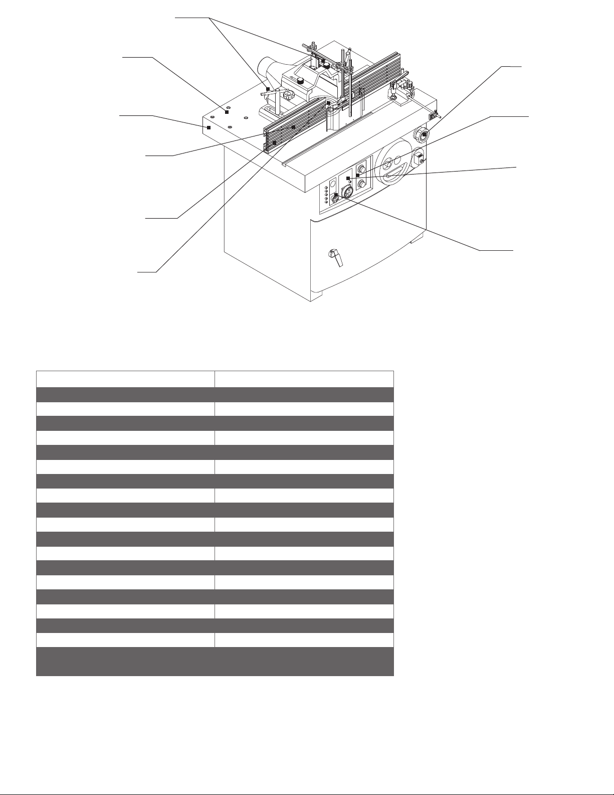
Ironwood FX 550 | User Manual4
Large, cast i ron,
ground and polished
table is rugged and stable,
with maximum rigidity for
heavy cutting operations
Generous table
for larger workpieces
Aluminum fence
assembly provides
for infeed and outfeed
independent fine adjustments
fence positioning
on the fence protect the
Adjustable fingers
operator from the cutter
and add support for the
workpiece.
11⁄4" interchangeable
spindle has over 6 " of spindle
capacity under the nut; other tooling
diameters a re also available
1.5 Technical Specifications
Description Ironwood FX 550
Working Table 27-9/16”x 35-7/16”(700x900mm)
Table Height 35-7/16”(900mm)
Spindle Capacity (under the nut) 6" (152mm)
Vertical Spindle Stroke
Spindle Speed 5 Speeds (3000, 4000, 6000, 8000, 10000 RPM)
Spindle Height Adjustment Handwheel
Spindle Position Display Mechanical Digital Readout
Spindle Size
Spindle Rotation Forward/Reverse
Max. Tool Diameter (Below Table)
Max. Tool Diameter (Above Table)
Fence Assembly Manual
Dust Port Diameter
Dust Extraction Requirements 1000 cfm @ 4,500 feet/min.
Motor 5.5 HP
Motor Power 230v (3 phase), 460v (3 phase)
Amperage 14.0 (230v) / 7.0 (460v)
Machine Weight 924 lbs. (420 kg.)
Shipping Dimensions (L x W x H) 42-15/16" x 34" x 42-1/8"
(1090mm x 864mm x 1070mm)
size provides support
Spindle locks with
safety limit switches
enhance safety
Convenient and
easy-to-use control panel
handles all control functions
Directional indicator
light for forward tnad reverse
spindle rotation control ensures
safe operation in clockwise and
counterclockwise applications
Emergency stop for
stopping motor with
the spindle brake in
10 seconds
7-1/16”(180mm)
1-1/4” x 6” (31.75mm x 152.5mm)
7-1/16” (180mm)
8-7/8” (225mm)
2 @ 4”
Ajustable Knobs both sides for
infeed and outfeed fence positions
help ensure precision
Ironwood FX 550 | User Manual 5
1.6 Safety Considerations
For your safety, read these instructions thoroughly before you install
and operate this machine. Always have these instructions available
at the machine for reference.
Observe all codes and regulations that apply to the installation and
operation of this machine.
Keep visitors at a safe distance from the workspace.
Keep children away from this and all machines. Childproof your
work area!
Familiarize yourself with the safety notices used in this manual.
CAUTION
If cautions are ignored, personal injury and/or machine damage
may result.
WARNING
If warnings are ignored, serious injury or death may result.
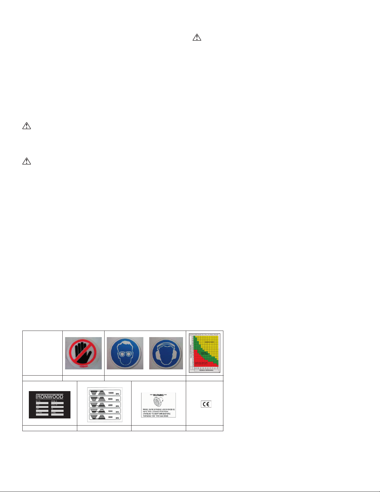
Warning Labels
This machine has warning labels attached to ensure safe operation.
These warning labels are very important and should be kept clean
and never be removed. If warning labels become damaged or lost,
contact Stiles Machinery immediately for replacements.
Label 1 Safety rules and features
Label 2 Do not touch turning spindle or cutters
Label 3 Always wear eye and ear protection
Label 4 Optimum speed range
Label 5 Hazardous voltage
Label 6 Belt placement/speed diagram (inside access door)
Label 7 Spindle lock
Label 8 CE marking regulations
Never use the FX 550 for purposes other than its intended use. Do
not modify or remove any guards or other safety features. Improper
use or modifications may affect your warranty or result in serious
injury or death.
Training
This machine is intended for use by authorized, well-trained
operators only.
Do not operate this machine until you have a complete working
knowledge of this shaper and have been properly trained for its
safe operation, correct adjustment and use. All operators should
thoroughly read and understand this manual and the workings of
this machine prior to operation.
It is essential that all operators be aware of the following:
• The dangers associated with the operation of this machine.
• The use of personal protective equipment for ear and
eye protection.
• The proper positioning of the operator and operator hands
relative to the cutters.
• The principles of machine operation, proper use and adjustment
of the fence, jigs, safety guards templates, extension tables and
end stops.
• The correct selection of tools and the associated spindle speeds
for each operation.
• The safe handling of the workpiece when cutting.
• The safe stacking of the workpiece before and after cutting.
• Connection of the optional power feed unit.
MAIN MOTOR
CAN ST AR T AND
OPERA TE THIS
MACHINE ONLY
IF THE DOOR IS
COMPLETELY
CLOSED AND
SECURED.
LABEL NO. 1 LABEL NO. 2 LABEL NO. 3 LABEL NO. 4
LABEL NO. 5 LABEL NO. 6 LABEL NO. 7 LABEL NO. 8
WARNING
Ironwood FX 550 | User Manual6
2.0 Facility Preparation
Prior to uncrating your machine confirm that your location can
accommodate the Ironwood FX 550. Follow these guidelines:
2.1 Floor
• The floor must be flat and level.
• Although no special foundations are required, a concrete floor
is recommended.
• All floors must have a load-bearing strength suitable for the
machine weight of approximately 814 lbs.
• If anchoring the machine to the floor, purchase high quality
anchor bolts appropriate to the floor construction and material.
2.2 Work Space
• Provide adequate work space surrounding the machine.
• Provide proper non-glare, overhead lighting.
• Place the machine so that any potential kickback area is not in
line with aisles, doorways, or other work and traffic areas.
• Provide adequate dust extraction system. The dust extraction
system should have a flow rate of 4,500 feet/min. at 1,000 cfm.
• Avoid exposure to any environment where vibration is present.
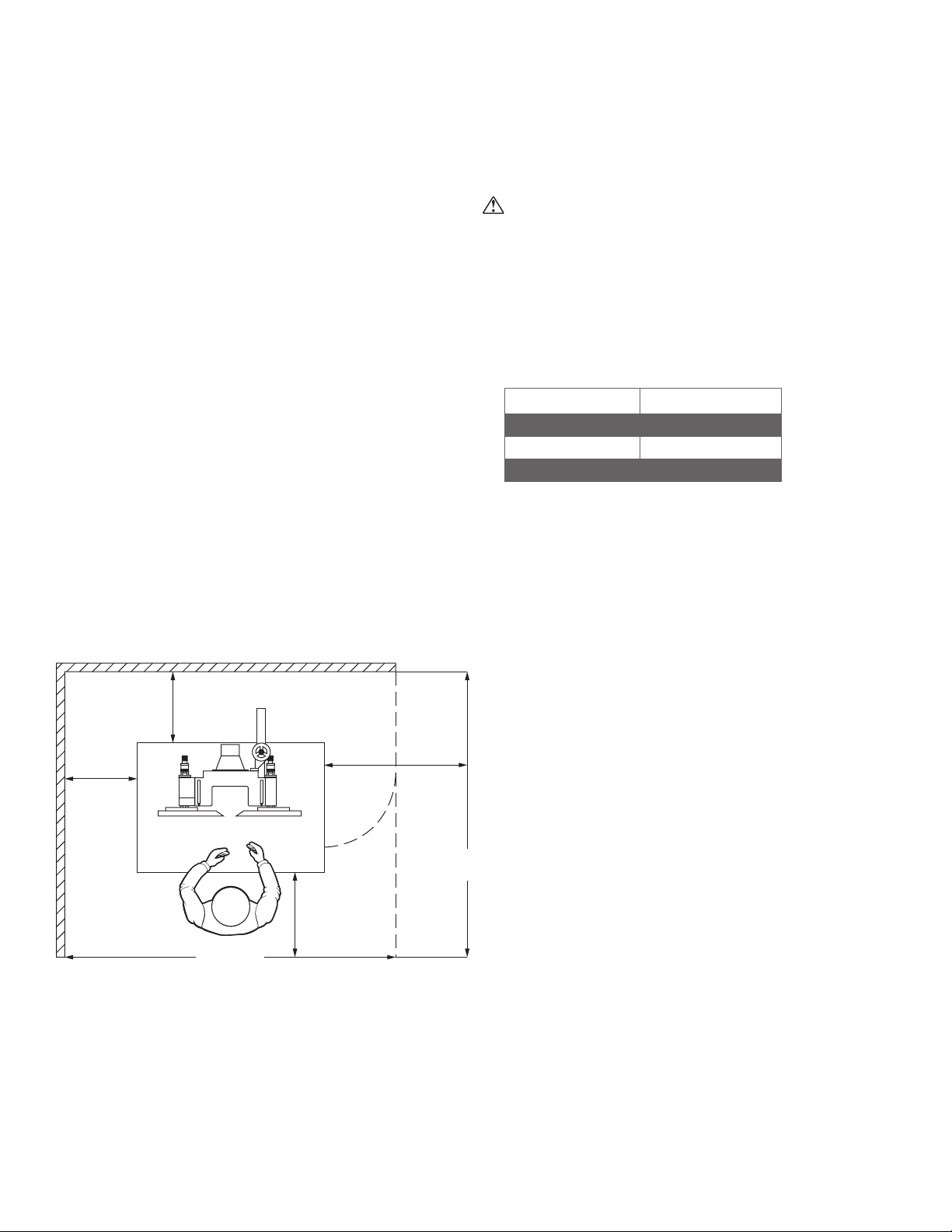
Standard machine clearance requirements*
1'-6"*
(500mm)
1'-6"
(500mm)
1'-6"*
(500mm)
2'-0"
(600mm)
6'-6"
(2000mm)
7'-6"
(2300mm)
*Actual clearance requirements may very depending on length of
material to be processed.
2.3 Power
WARNING
A licensed electrician must connect the FX 550 to the building
power source.
• Do not using extension cords.
• Be sure that the electrical current of the power source is of the
same characteristics as the electrical system supplied with your
machine. If other machine voltage capabilities are required,
contact Stiles Machinery.
FX 550
Motor 5.5 HP
Motor Power 230v / 460v (3 phase)
Amperage 15.6 (230v) / 7.6 (460v)
• Ensure the machine is protected with an external over-current
protective device per your local electrical codes.
• Electrical equipment operating conditions:
• Air temperatures between +41ºF (+5ºC) and +113ºF (+45ºC).
• Relative humidity not to exceed 50% at a maximum temperature
of +113ºF (+45ºC).
• Electrical equipment is designed and protected to withstand the
effects of transportation and storage temperatures within a range
of -13ºF (-25ºC) to +131ºF (+55ºC), and for short periods of time
not exceeding 24 hours at up to +158ºF (+70ºC).
• Ensure connection to factory ground system is wired correctly
(IAW local electrical codes and NEC) and not connected to any
electro magnetic interference source such as welders.
Ironwood FX 550 | User Manual 7
3.0 Delivery and Installation
3.1 Receiving Your Machine
You will be contacted to arrange delivery. Your machine will be
delivered by truck to your location. If there is no loading dock, be
sure that you have informed the carrier in advance so that they
deliver using a truck with a lift gate to lower the machine to
ground level.
Before accepting the machine and signing the bill of lading from
carrier, please inspect crating and machine condition, note potential
damage on the bill of lading, take pictures of potential damage, and
contact Stiles Machinery immediately.
The machine will arrive fully crated and secured to a pallet. Use a
hand truck or fork lift to move the machine on its pallet as close to
its final position as possible.
If you do not intend to install the Ironwood Shaper immediately after
delivery, store it in a protected, cool, and dry location.
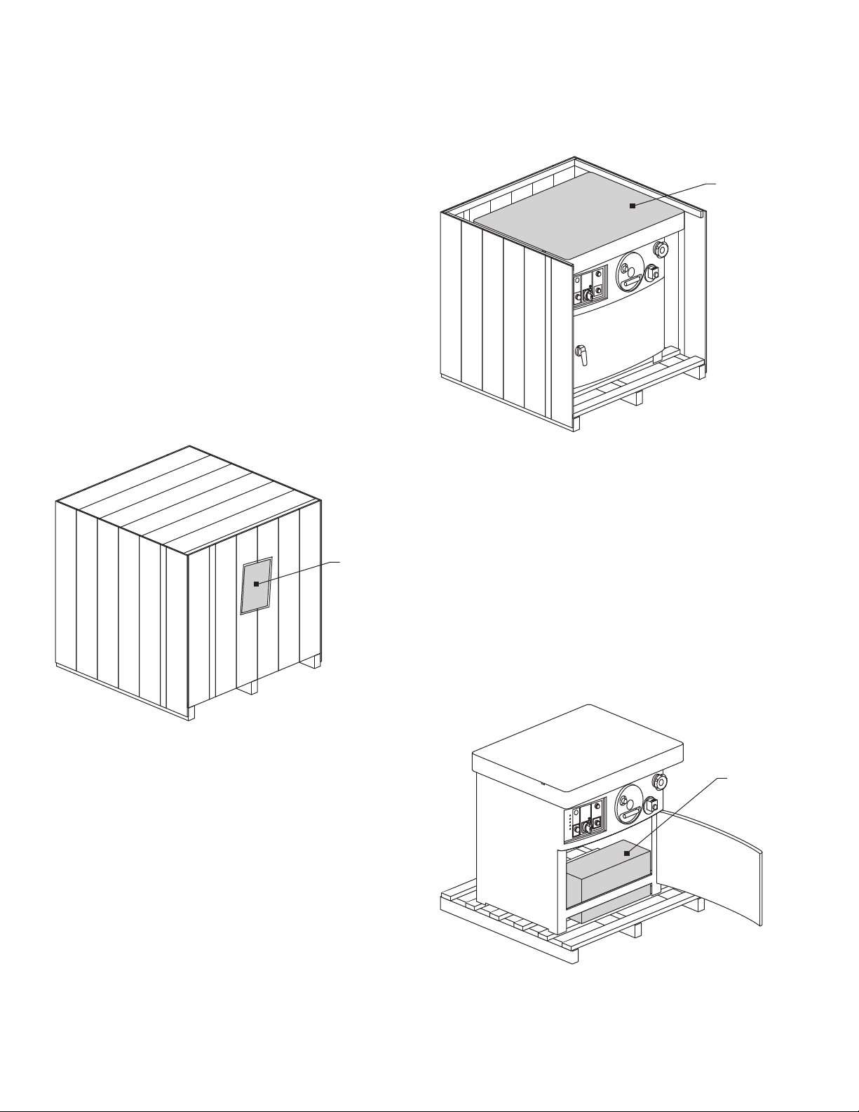
The machine
arrives fully
crated. Remove
and save the
paperwork
attached to
the outside.
3.2 Unpack the Machine
TOOLS REQUIRED:
• Hammer
• Crowbar
Unpack as follows:
Do not remove the machine from the pallet.
1. Remove and save all paperwork attached to the outside of
the crate.
2. Remove the crating, starting with the top, then remove the four
sides. Use caution to avoid personal injury and prevent damage
to the machine’s finish.
3. Remove the protective plastic from the machine, starting at
the bottom.
Remove the
crating, starting
with the top,
then remove
the four sides.
Do not remove the protective paper that covers the
tabletop surface.
4. Remove the plastic sleeve from the front access door handle.
The door is locked when the handle is in the vertical position.
Turn the handle to the right to unlock and open the
access door.
5. Remove the hardware, accessories, and a tool kit that are
shipped inside the machine. If additional accessories are
ordered, such as a power feeder, they are delivered on
a separately.
6. Close and lock the front access door.
Remove the
parts stored
inside the
machine.
Ironwood FX 550 | User Manual8
3.3 Inspection
Save all containers and packing materials until you are satisfied
that your machine has arrived in good condition. If you discover the
machine is damaged after you’ve signed for delivery, immediately
call Stiles Customer Service.
When you are completely satisfied with the condition of your
equipment, you should inventory its parts.
Open and check the contents of all containers to ensure all tools,
hardware, and accessories are included. The tool kit should contain
the following items:
1. 6-piece open end wrench set
2. T-wrench for fence with adjustable supporting bar
3. Spanner wrench for spindle retaining nut
4. 11⁄4" spindle nut wrench
5. 11⁄4" x 6" (152mm) spindle set with safety nut
6. 7-piece Allen wrench set
7. Grease gun
8. Cabinet handle key for locking/unlocking cabinet access door
9. Handwheel
10. Paint (2-color set)
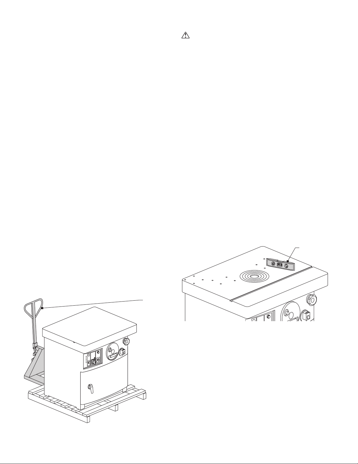
3.4 Move Machine to Final Position
Be sure the site is properly prepared. Refer to section 2.0 for details.
Be sure the front access door is closed and locked
before transporting.
TOOLS REQUIRED:
• Hand truck or fork lift
Use a hand truck or fork-lift to move the machine on its pallet to
its final location. If using a fork lift, make sure fork travel is clear of
any obstacles.
Use a hand
truck or fork
lift to move
the machine.
3.5 Remove Machine from Pallet
CAUTION
The FX 550 weighs 814 lbs. For this procedure, we
recommend using four people.
TOOLS REQUIRED:
• Adjustable wrench
• Access door key
Carefully remove the machine from the pallet.
1. Remove the two bolts that secure the fence assembly.
2. Remove the fence assembly.
3. From inside the cabinet, remove the four 1/2” (13mm) bolts that
secure the machine to the pallet at the interior corners.
4. Lift the machine from the pallet by one of 2 methods:
a. Team lift
b. Slide machine onto forks of fork lift
5. Carefully slide the machine into final position.
3.6 Level
TOOLS REQUIRED:
• Bubble Level
• Adjustable wrench
Use a bubble level along the length and width of the tabletop surface
to check for level. Use an adjustable wrench to adjust leveling bolts
to level machine.
Be sure to level
the machine.
Ironwood FX 550 | User Manual 9
3.7 Pre-Operation Cleaning
WARNING
Use proper cleaning agents and methods described below. Do not
use gasoline or other petroleum-based solvents. Risk of fire
or explosion.
Machine Tabletop Surface
Remove and discard the protective paper from the top of the
machine. Use a soft cloth and nonflammable degreasing agent, such
as Simple Green or other citrus-based cleaners to carefully clean off
all grease. Do not use abrasive pads.
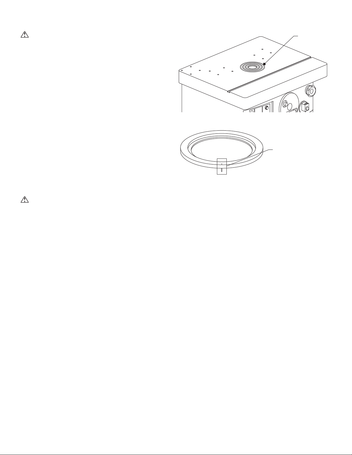
Table Rings
Spindles are fitted with up to three table rings for a wide variety of
tooling configurations. Table rings may be inserted or removed
individually. Remove and clean the rings, starting with the
innermost ring.
Be aware that the rings fit tightly. To remove a ring, place fingers
inside ring and position on opposite sides. Gently rock the ring
back and forth to release the pin. Remove all rings and clean with
degreasing agent.
CAUTION
Threads on the spindle and spindle shaft are very sharp. Use care
when cleaning to prevent injury.
With all rings removed, thoroughly clean the taper of the spindle and
the internal taper of the spindle shaft.
To replace the rings, start with the outer ring. Align the locator pin
on the bottom of the ring with the insert on the outer rim. Repeat for
each ring.
Table rings are
supplied with
the machine.
Outer ring with
locator pin.

Ironwood FX 550 | User Manual10
4.0 Assembly
To be assembled:
• Fence Assembly and Fences
• Spindle
• Cutter Head/Tooling
• Top Dust Cover
• Safety Guard Assembly
• Mitre Gauge Assembly and Clamp
4.1 Fence Assembly and Fences
CAUTION
For this procedure, we recommend using two people.
PARTS REQUIRED:
• Fence assembly
TOOLS REQUIRED:
• Allen wrench set
• Adjustable wrench
The fence should always be used for straight work cutting to guide
the workpiece.
The fence has two halves: An infeed fence and an outfeed fence.
Both must be installed to the fence assembly. The infeed fence is on
the right as you face the machine; the outfeed fence is on the left.
The cast iron fence assembly is adjustable, and the slotted
aluminum fences can be adjusted to maximize safety and allow
precision shaping for every cutter used on the machine. Independent
fine adjustments and digital readouts are included to precisely
position infeed and outfeed fences. Quick fence changeovers
provide the flexibility needed to create quality profiles in a short time.
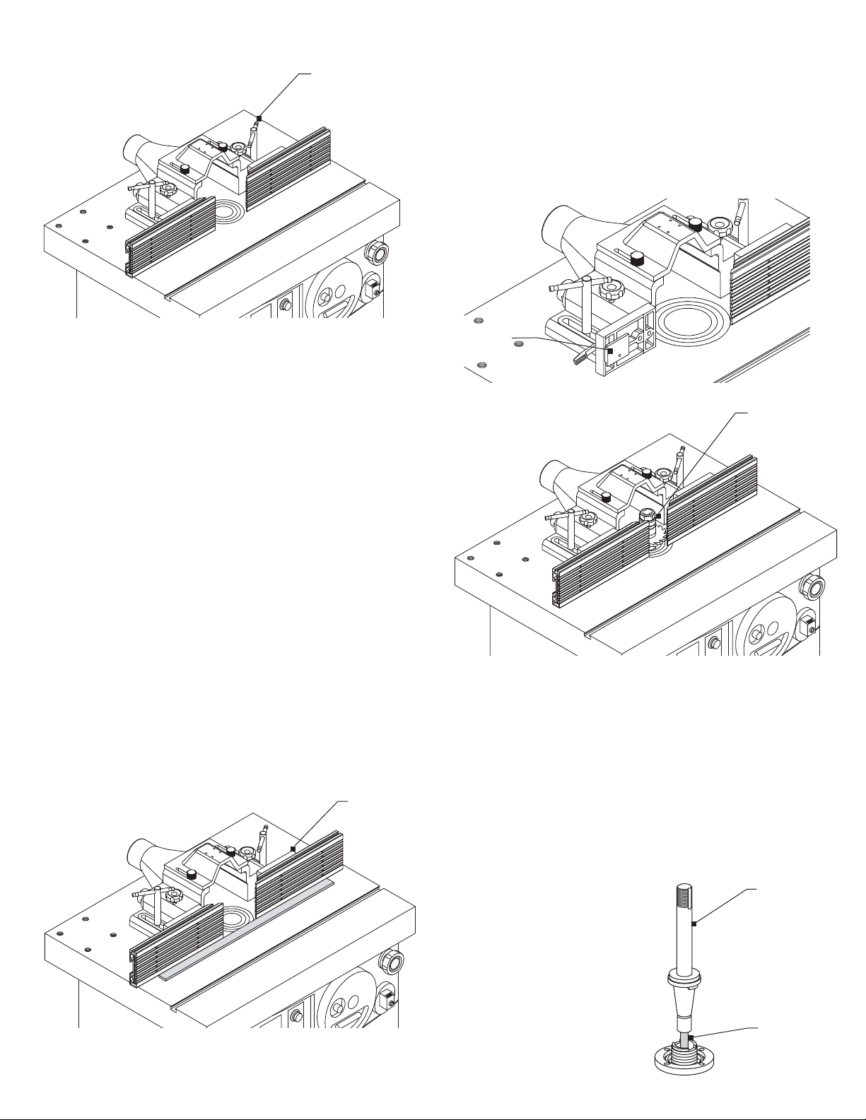
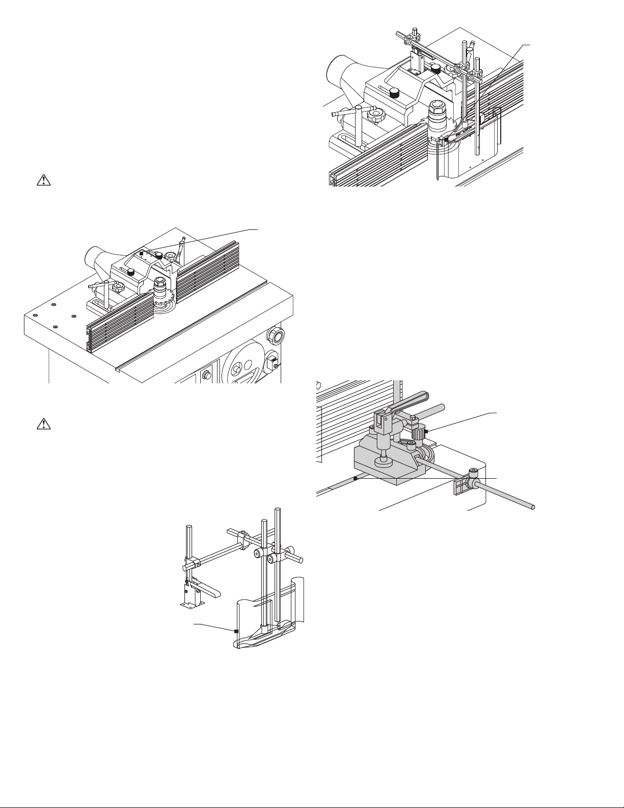
Fence assembly
(front and back views).
1. Locate the bracket at the rear of the table. Remove the screws
from the horizontal arm of the bracket and set them aside.
2. Place the fence assembly body on the rear of the table as
shown, aligning the forward set of pilot holes with the
bracket holes.
3. Reattach the screws to secure the fence to the bracket. Do not
fully tighten.
4. Fasten locking bars to the front of each fence block half using
the locking lever and washer. Locking levers are spring-loaded
and can be repositioned by pulling out the handle or by using
an Allen wrench.
5. With the locking levers loosened, slide the infeed fence half and
outfeed fence halves onto the locking bars. Be sure the beveled
end of each fence faces the center of the table. Tighten each
fence using its locking lever and washer.
Fences attach
to the fence
block
6. Locate the two fence locking handles and washers. Attach
the handles in the slots. Position the fence so that the locking
handles align with the forward two sets of holes located on the
machine table. Tighten the locking handles.
7. To reposition the complete fence assembly on the table, loosen
the two locking handles, move the fence assembly to the
desired position, and tighten the two locking handles.
Infeed
fence
Outfeed
fence
Ironwood TS 750 | User Manual
Ironwood FX 550 | User Manual 11
Be sure the fences
are be aligned
Locking handles
Moving fence assembly
The fence assembly is moved in an out to roughly align fence and
move into the desired position.
To move the fence assembly, loosen locking handles located on top
of the fence assembly until the fence assembly is in the desired
position. Tighten the locking handles to secure.
Moving infeed and outfeed fences
Each fence half (infeed and outfeed fence) can be moved
independently, in or out, depending upon the type of shaping
operation to be performed.
To move fence(s) in or out, loosen one of the locking knobs and turn
one of the adjusting knobs until the desired setting is obtained on
the digital readout. Tighten the locking knob.
Aligning infeed and outfeed fences
1. Place a solid steel ruler along the infeed and outfeed fences,
adjust the fences so they are parallel to one another.
Fences are
adjustable
2. Adjustment of the fences depends upon the configuration of
your machine. If adjusting screws are present on your model,
adjusting screws will be used for alignment. To adjust fences
for parallelism, either adjust adjustment screws or place shims
between the round rods and fence block until both fences are
parallel to one another. Fences are aligned at the factory but
may move during shipping. Check parallelism before continuing
with procedure.
Adjustment point
is shown behind
the plate
Adjust the fence
gap in relation to
the cutter.
4.2 Spindle
PARTS REQUIRED:
• Spindle
• Drawbar
TOOLS REQUIRED:
• Spanner wrench
• Adjustable wrench
1. Remove table rings for easy access to main shaft.
2. To access the locking collar, use the handwheel on the front of
the machine, raise the main shaft all the way to the top.
3. Thread the short-threaded end
of the draw bar into the threaded
hole in the bottom of the spindle.
This is the end without the 2 nuts
and bevel washer.
4. Remove the two lock nuts and
bevel washer from the other end
of the draw bar.
5. Carefully insert the draw bar and
spindle down through the shaft.
Spindle
Draw bar
threaded
into spindle
Make sure
the lip on the
spindle is
engaged with
the notch.

Ironwood FX 550 | User Manual12
Make sure the lip on the spindle is engaged with the notch on
lock nuts and bevel washer on the bottom of the draw bar as
shown in picture. Ensure the bevel washer is put on the draw
bar before the 2 lock nuts. Tightening the drawbar will center
the spindle.
6. Engage the spindle lock. The spindle lock is provided to assist
when changing the spindle or installing and removing cutters.
Two lock nuts and a bevel
washer attach to the
bottom end of the draw bar.
• To lock the spindle, turn the knob counterclockwise and
push into the locked position.
• To unlock the spindle
so it rotates freely,
pull out the knob
and turn clockwise.
The knob will latch
into the unlocked
position.
The manual lock has a
limit switch to prevent the
motor from starting when
engaged.
7. Securely tighten the two lock nuts
with wrench.
8. Thread the spindle safety nut onto the
threads.
9. Tighten the spindle safety nut, using
the spanner wrench supplied with
machine.
4.3 Cutter Head/Tooling
PARTS REQUIRED:
• Spacers
• Tool/cutter head (Not supplied. To
source or for more information, contact Stiles Machinery.)
TOOLS REQUIRED:
• Spindle nut wrench
Install the cutter head or other tooling on the spindle.
Spindle
lock knob
Tighten
the spindle
safety nut.
WARNING
The cutter is extremely sharp. Use caution when handling or working
with the cutter.
1. Place the cutter head and spacers onto the spindle. Place the
tool as close to the bottom of the spindle as possible.
2. Attach the keyed washer on the spindle, making sure the
washer engages the grooves on the spindle.
WARNING
Always place the keyed washer on the spindle before threading on
the nut. The keyed washer prevents the nut from loosening when the
spindle turns in a counterclockwise direction.
3. Be sure that the top retaining nut and top spacer are in
firm contact.
CAUTION
There must be no gap between the bottom of the retaining nut
and the top of the uppermost spacer. Any gap that exists during
operation could result in significant damage to the spindle.
4. Attach and tighten the nut with all threads engaged using the
provided spindle nut wrench.
5. Disengage the spindle lock as explained in 4.2 Step 6.
CAUTION
The cutter should be positioned on the spindle so that the cut is
performed from underneath the surface of the workpiece.
WARNING
After installing or replacing cutters and before operating the
machine, carefully check to ensure that the direction of the cutter
and keyed washer is correct, and that the spindle rings are directly
underneath the spindle nut and securely tightened.
Retaining
ring nut
Spacer
Cutter
Spindle
safety nut
Tooling
attaches to
the spindle.
Secure
tooling to
the spindle.
Ironwood FX 550 | User Manual 13
4.4 Top Dust Cover
PARTS REQUIRED:
• Dust cover assembly
TOOLS REQUIRED:
• Allen wrench
Assemble the top dust cover to the top of fence body using the
two locking knobs and washers included in your attachment
hardware pack.
WARNING
Do not operate the machine without the dust cover attached.
The top
dust cover
attaches
to the
fence body.
4.5 Safety Guard Assembly
WARNING
Always use the safety guard assembly and hold-down when
operating the FX 550. Select and adjust the safety guard to the
tooling currently being used.
PARTS REQUIRED:
• Safety guard assembly
TOOLS REQUIRED:
• Allen wrenches
1. Attach the guard base to
the fence assembly body at
the pilot hole locations using
screws provided.
2. Attach a bracket to the
vertical bar in the base,
with the bracket facing
the operator. Loosely
attach the bar using an
Allen wrench and set screw.
3. Loosely install a horizontal bar on the bracket. Loosely attach
a bracket at the other end, with the bracket facing up. Loosely
install the other horizontal bar so it extends toward the operator,
beyond the fence. Attach two brackets with hand screws at the
other end of the horizontal bar.
4. Attach the orange hold-down to the end of the inner vertical bar.
5. Attach the clear plastic safety guard to the outer vertical bar
using set screws.
Always use
the safety
guard assembly.
The safety guard
is installed on the
fence assembly.
6. Once the safety guard assembly is configured as shown, tighten
all set screws.
The safety guard hold-down assembly can be angled up out of the
way using the adjustment lever.
4.6 Miter Gauge Assembly and Clamp
Use a miter gauge to make small or angled cuts.
PARTS REQUIRED:
• Miter gauge assembly
TOOLS REQUIRED:
• None
Mitre gauge
assembly.
Mitre gauge
bar.
1. Angle the hold-down and safety guard up out of the way.
2. Locate the miter gauge bar and insert the bearing of the bar
into the T-slot of the machine table.
3. Place the miter gauge on the bar, with the stud of the bar
protruding up through the opening in the miter gauge body.
4. Fasten in place using washer and locking knob.
Stop Bar
1. Insert the stop bar into the hole on the side of miter gauge
body, and lock into place with locking knobs.
2. Assemble the stop to the stop bar as shown in image above,
and tighten the locking knob.
Clamp
A clamp is supplied with your miter gauge to securely hold
workpieces. The clamp can be moved up or down as required.
Ironwood FX 550 | User Manual14
5.0 Connect to Power
• Voltage – Steady state voltage +/- 10% of nominal voltage
@230v +/- 10% of voltage @460v .
• Machine needs steady voltage at all times.
WARNING
Before connecting power to the machine, make sure all screws and
fasteners are tightened, all mechanical functions work freely and the
cutter turns freely without touching the table rings.
WARNING
All connections to electrical power should be completed by a
licensed electrician.
Before connecting to a power source, confirm that the electrical
current of the power source is the same as the electrical system
supplied with your machine. Ensure the machine is protected
with an external over current protective device per your local
regulating authorities.
Machine must be properly grounded to prevent electric shock.
Never connect the yellow/green wire to a live terminal.
Once connected to power source, terminals are electrified even
while the power switch is off.
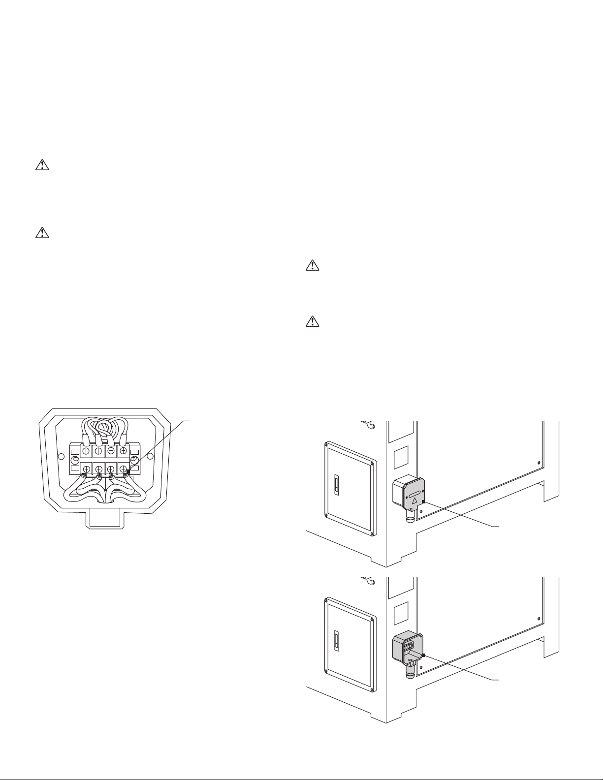
L3
234
L2L1 PE
PE
L1
L2
1
L3
Proper wiring inside
the terminal strip box
To connect source power to the machine:
1. Remove two screws and remove terminal box cover.
2. Remove clear plastic insulator that covers the terminals.
3. Insert source power cables through opening of terminal box.
4. Connect the three power cables to terminals L1, L2 and L3,
and the yellow/green ground wire to ground terminal.
5. Replace the clear plastic insulator and the power box cover.
6. When wiring is complete, tape all terminal box joints to keep out
dust and debris.
WARNING
Always shut off power at source before removing terminal box cover.
Failure to comply with this action may result in electric shock.
CAUTION
We have covered some basic electrical requirements for the safe
installation of your machine. These requirements may not cover
all installation requirements. You must confirm that your particular
electrical configuration complies with all local codes. Ensure
compliance by checking with your local municipality and a
licensed electrician.
Remove terminal
box cover.
Remove the clear
plastic insulator that
covers the terminals.
Connect power and
grounding wires.

Ironwood FX 550 | User Manual 15
6.0 Safety
WARNING
Like all power equipment, there is danger associated with the
Ironwood FX 550. Use caution and follow all safety instructions.
Take every precaution to protect yourself, others around you, and
the machine itself from improper use. Safety is a combination of
common sense, training, and being alert at all times while operating
your machine. If instructions, warnings, and cautions, are not
followed, serious personal injury or death may occur.
EYE PROTECTION: Always wear approved safety glasses, or a
face shield when operating this machine. Only use eye protection
that meets or exceeds the standards of the American National
Standards Institute (ANSI).
EAR PROTECTION: Always wear ear protection during
machine operation.
DRESS CODE: Do not wear loose clothing, neckties, jewelry, or
gloves that can get caught in moving parts. Confine long hair and
keep sleeves above the elbow.
ELECTRICAL GROUNDING: Your machine must be electrically
grounded. If a cord and plug are used, make certain the machine is
properly grounded. Follow the grounding procedure indicated by the
National Electric Code and local regulating authorities.
GUARDS: Make certain that machine guards are in place and in
good working order. If a guard must be removed for any operation,
replace it immediately following completion of that operation.
TOOLING AND ACCESSORIES: Use only recommended tooling
and accessories. Improper tooling and accessories may cause
damage to your machine or personal injury. Always run at the
correct speed and feed rate. Never force a tool or accessory to
perform a job for which it was not designed. Maintain your tools
and accessories. Knives should be sharpened and cleaned for
safe, optimal performance. Follow instructions for lubricating and
changing tooling and accessories.
POWER: On machines equipped with a manual starter, make sure
that the starter is in an “OFF” position before connecting power to
machine or electrical maintenance.
Make certain the machine is either unplugged or electrically
disconnected and locked out when performing all other
maintenance, cleaning, or machine adjustments. Never leave the
machine running unattended. Always turn the power off and stay by
the machine until the cutterhead comes to a complete stop.
HOUSEKEEPING: Before turning machine on, remove all extra
items on or around the machine. Keep the work area clean and free
of scrap material, sawdust and other debris to minimize the danger
of slipping. Use compressed air or a brush to remove chips or
debris. NEVER use your hands.
Ironwood FX 550 | User Manual16
7.0 Start the Machine
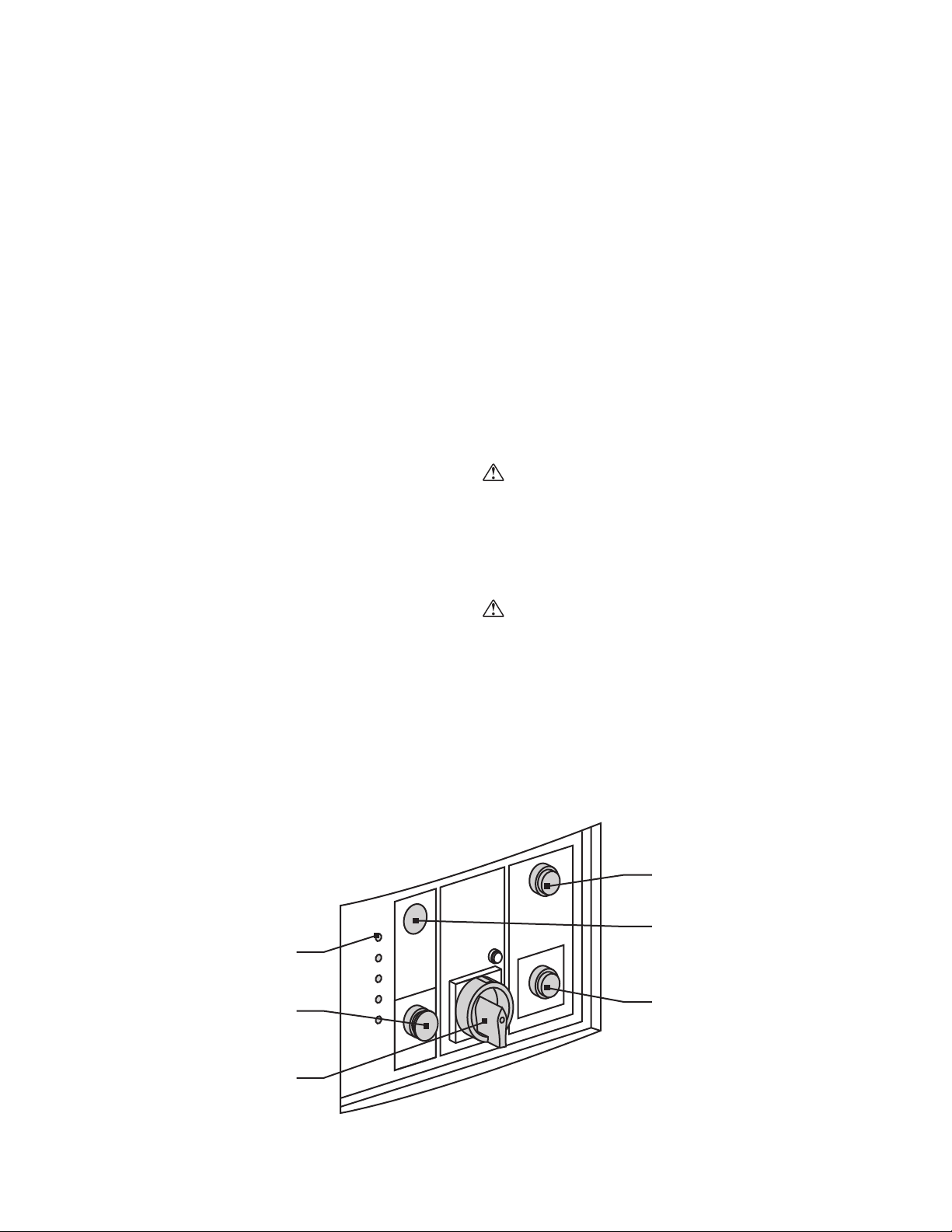
7.1 Control Panel
The control panel on the front of the machine handles all control
functions. It has the following features:
A. Speed indicator
B. Emergency stop
C. Forward/Reverse/Off switch
D. Spindle Reverse light
E. Control Power on Switch
F. Control Power off Switch
7.2 On/Off
Use the following procedure to start or stop the machine:
1. Make certain that the spindle lock is disengaged and that the
front access door is in the closed position.
2. Check rotation of spindle motor by turning motor on and off
very quickly. Observe direction of rotation. If spindle rotation is
backwards, do the following:
a. Turn power off to the machine.
b. Turn off main power supply / disconnect the machine.
c. Open terminal box, remove plastic covers and test with as
multimeter to ensure there is no power at the machine.
d. Swap leads L1 and L2 to change phase rotation.
e. Reassemble terminal and plastic covers.
f. Turn on main power supply / connect the machine
g. Turn power on to the machine.
h. Repeat steps to check direction.
3. Rotate the Forward/Reverse/Off switch to either the forward or
reverse rotation depending on tooling.
4. Push the Control Power On switch to start the machine.
5. To stop the machine, push either the Control Power Off button
(preferred method), or turn the Forward/Reverse/Off switch to
the middle.
In an emergency press the Emergency Stop button.
a. When servicing the machine, press the power off button
and turn the main on/off switch to 0, then place a sign
on machine and install padlock on the main on/off switch
before servicing it.
The electrical cabinet door must be closed except while servicing or
troubleshooting.
WARNING
When opening the electrical door, make certain that the main power
switch is shut OFF. Failure to comply with this action may result in
electric shock.
7.3 Reverse Spindle Rotation
CAUTION
Never attempt to reverse the rotation of the spindle while the motor
or spindle is in motion. Control power will drop out when the switch
is turned to the middle/off position.
To reverse the rotation of the spindle, shut off the motor then rotate
the forward/reverse/off switch after the spindle has come to a
complete stop.
E
D
F
C
B
A
Ironwood FX 550 | User Manual 17
8.0 Operation
WARNING
Do not attempt to operate machine if you are not completely familiar
with its operation. Obtain immediate advice from a supervisor,
instructor, or other qualified personnel.
Use of this machine requires that you give your work your undivided
attention, and careless acts or not paying close attention to work
being performed may result in serious injury to yourself and/or
others. Never operate this or any machine under the influence of
drugs, alcohol, or any medication that may impair judgement.
SPINDLE: Make sure the direction of the spindle’s rotation is
correct. Start the machine to ensure it rotates in the correct
direction. The rotation direction should correlate with the spindle
rotation indicator light. The light is on only if the direction is in
reverse. If the direction is incorrect, check the power phase
sequence and have it corrected by a licensed electrician and see
section 6.3.
Dust created by manufacturing activities may be harmful to
your health.
Your risks from exposure may vary. Always work in a well-ventilated
area and wear safety approved, protective dust masks specifically
designed to filter out microscopic particles. Utilize wood dust
collection systems appropriate to your machine type.
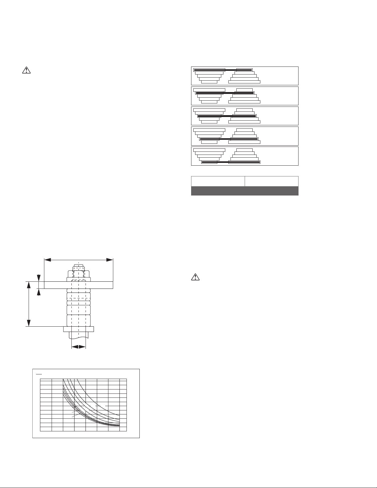
d1:
spindle
diameter
d2:
tool cutting
diameter
b:
length of cut
d1
l
1
b
d2
l1:
maximum
useable length
of spindle
10000
RPM
8000
RPM
6000
RPM
4000
RPM
3000
RPM
Spindle dia. Tool length
30 mm 140
AVOID KICKBACK: It is very important that each workpiece be
carefully inspected for stock condition and grain orientation before
running through the machine. “Pull-out” and the danger of kicked
back material can occur when the workpiece has knots, holes, or
foreign materials such as nails. It can also occur when the material is
fed against the grain on the shaper. The grain must run in the same
direction you are cutting.
Use of a power feeder greatly reduces the risk of kickback.
CAUTION
During certain applications, it may be necessary to shape against
the grain. This application requires that the operator use a shallow
depth of cut and a slower feed rate.
0
0
1
2
3
4
5
b = 140
b = 120
b = 100
6
7
8
9
10
11
12
50 100 150 200 250 300 350 d2(mm)
d1= 30 mm l1= 140 mm
1000 (min-1)
nmax
b = 10
b = 20
b = 30
b = 50
b = 80
10
11
12
1000
Ironwood FX 550 | User Manual18
8.1 Speed Change and Belt Adjustment
Confirm that the selected spindle speed matches the suggested
spindle speed provided by the tooling manufacturer.
Before operation, check that all tools are sharp, are the correct tool
for the work to be performed, properly maintained and adjusted
according to the tool manufacturer’s instructions.
There is a relationship between tool diameter, cutting length, and
maximum rotation speed.
The maximum safe spindle speed depends on:
• Spindle diameter
• Usable length of spindle
• Length of cut
• Tool cutting diameter
• Tool specifications per the spindle manufacturer
The following charts can be used as a reference guide for the
maximum spindle speed for various tool cutting diameters given the
values of d, l, and b. Always refer back to the ratings provided by the
tool manufacturer.
Reminder: Always place the tool as close to the bottom of the
spindle as possible.
The FX 550 machines are supplied with a 5-step motor pulley and a
5-step spindle pulley that provides spindle standard speeds of 3000,
4000, 6000, 8000 and 10,000 RPM.
A chart (Label 6) is located on the inside of the access door for
easy reference of the belt position on the pulleys for the five
speeds available.
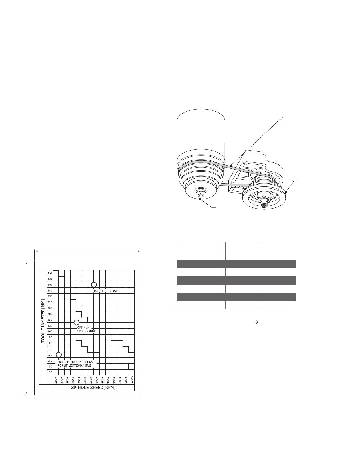
OPTIMUM SPEEDRANGE FORTOOLS ON SPINDLE MOULDER
95
120
1. Hazard: bad machining conditions
2. Bursting hazard
3. Recommended spindle tool speed
1
2
3
Confirm the machine’s speed settings before operating. Make
certain that the cutter meets or exceeds speed rating of tool.
The diagram is an example of choosing a speed in relation to the
diameter of the tool, and the most appropriate peripheral speed for
the type of material that is being worked on. Always refer back to the
ratings provided by the tool manufacturer.
Cutting speed should always be sufficient to prevent kickback risk,
but never fast enough to cause tool damage.
The cutting speed range m/sec (lower and upper) is selected
according to the tool diameter (mm) D (left vertical axis), and the tool
spindle speed N min-¹ (bottom horizontal axis).
The belt attaches
to the motor
pulley and
spindle pulley.
Spindle
pulley
Motor
pulley
Guide values for cutting speed
Material Cutter HS
(m s-1)
Cutter HW
(m s-1)
Softwood 50-80 60-90
Hardwood 40-60 50-80
Chipboard — 60-80
Coreboard — 60-80
Hard fibreboard — 40-60
Plastic-coated board — 40-60
Example:
Cutter: 160 mm diameter, vc= 76m s-1 n = 9000 min-1
Cutter speed formula:
v = (D x π x N) / (60 x 1000)
D: Tool diameter (mm)
N: Tool spindle speed (rpm)

Ironwood FX 550 | User Manual 19
WARNING
Always operate a tool at the speed range set by the manufacturer.
Failure to do so may result in serious injury or machine damage.
To change the speed and adjust to proper belt tension:
1. Disconnect the machine from its power source.
2. Open the access door. NOTE: A limit switch is provided which
prevents the machine from being turned on when the access
door is open.
3. The belt can be moved to the desired steps of the motor pulley
and spindle pulley. To loosen belt tension, move the belt tension
lever to the right. At the same time, rotate the knob to slide the
speed bar up or down so that the belt will be positioned in the
cut-out in speed bar.
4. After the belt is positioned as desired, move the tension lever to
the left to apply tension to the belt.
5. Close and latch the access door.
Note: After a short time, the belt may stretch. Check tension by
pressing the center of the belt with a force of 6.6 lbs (3 kg.) Tension
is correct when 3⁄16" (5mm) of defection is observed. Turn the two
nuts to adjust best belt tension.
Never place the V-belt under excessive strain, as this can overload
the motor and damage the bearings, spindle or belt.
8.2 Spindle Height Adjustment
Adjust spindle height to achieve the desired cut. The spindle height
can be precisely measured using the digital readout feature.
1. Loosen handwheel lock and spindle locking lever.
2. To raise the spindle, turn handwheel counterclockwise and to
lower the spindle, turn handwheel clockwise.
3. Note: One complete turn of the handwheel moves the spindle
up or down by 1mm or 2.5 mm indicated on the machine frame
(sticker).
4. Tighten handwheel lock and spindle locking lever when desired
spindle height is obtained.
8.3 Using Fence(s)
WARNING
Keep guards in place and in working order. Always use the fence
assembly when work permits.
Using the fence is the safest and most accurate method of shaping,
and should always be used when work permits. The majority of
straight work can be performed using the fence.
For normal work, where a portion of the original edge of the stock is
not touched by the cutter, both the infeed and outfeed fences are in
a straight line.
When the shaping operation removes the entire edge of the
workpiece, e.g. in jointing or making a full bull nose, the shaped
edge will not be supported by the outfeed fence edge when both
fences are in line. In this case, the workpiece should be advanced
to the position shown and stopped. The outfeed fence should then
be moved forward to make contact with the workpiece. The outfeed
fence will then be in line with the cutting circle, and the operation
can continue.
Cutting Circle
Cutter
Outfeed Fence Infeed Fence
No Support Workpiece
Feed
For some shaping
operations, the
outfeed fence should
be moved forward to
support the workpiece.
Cutting Circle
Cutter
Outfeed Fence Infeed Fence
Workpiece
Feed
For normal work,
the infeed and
outfeed fences are
in a straight line.
Note: All Ironwood shapers accommodate Stiles power feeders.
Power ports are included on the rear of the machines. For more
information review operators instructions included with the power
feeder or contact Stiles machinery.
8.4 Adjusting Fence Extensions
WARNING
To eliminate gaps between the edges of the fence and cutter, both
fences should be adjusted as close to the cutter spindle tooling
as possible.
For added safety, the fence extensions can be adjusted to the
height of the cutterhead so that you expose only the amount of tool
required to make a safe cut is exposed.
Using an Allen wrench, loosen the aluminum fence extensions, slide
them horizontally into desired position, and tighten.
Ironwood FX 550 | User Manual20
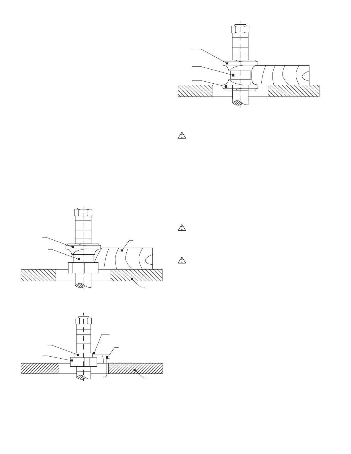
8.5 Positioning and Using Collars
When shaping with collars, the collar must have sufficient bearing
surface. Also, the workpiece must be fairly heavy relative to the cut
being made.
The collars may be used above, below, or between the cutters.
Under no circumstances should you shape a short or light work
piece against the collars.
When the collar is used below the cutter, the progress of the cut can
be seen throughout the operation. However, any accidental lifting of
the workpiece will gouge the product and ruin the workpiece.
When the collar is used above the cutter, the cut cannot be seen,
but this method offers an advantage: the cut is not affected by light
variations in the thickness of the workpiece. Also, accidental lifting
of the workpiece will not gouge the work piece; simply repeat the
operation to correct the mistake.
Using the collar between two cutters has advantages and
disadvantages of the first two procedures, and is frequently used
where both edges of the work are to be molded.
Note: Place the cutter as low as possible on the spindle to reduce
spindle deflection and ensure the best possible finish. Also, make
sure that the contacting surfaces of the cutter are smooth, clean,
and without dents.
Table
Cutter
Collar
Workpiece
Collar below cutter:
the progress of the cut
can be seen throughout
the operation.
Table
Collar
Cutter
Workpiece
Be sure there’s enough
bearing surface and that
the workpiece is not too
short and light.
Insufficient
bearing surface
Workpiece
is too small
WRONG
Cutter
Cutter
Collar between two
cutters: used where
both edges are to be
molded
Collar
8.6 Tenoning
WARNING
Keep guards in place and in working order.
The miter gauge and clamp provided with the machine can be used
for tenoning operations.
If your machine is equipped with a tenoning carriage, the tenoning
hood fitted with adjustable sections is used to guard the tool from
above the workpiece and from the sides.
Various tenoning carriages are available. For more details contact
Stiles Machinery.
8.7 Tool Adjustments
WARNING
Tools are extremely sharp. Be careful when working with tooling as
serious injury may occur.
CAUTION
Always disconnect the machine from its power source before
making any adjustments.
To reduce kickback, use only tools that conform to EN 848-1:2005
and EN 848-2:2001, and that are marked MAN.
Refer to the tool manufacturer’s recommendations for clamping and
setting of tools.
To ensure safe and efficient cutting, the tooling should be suitable for
the material being cut. The tools should be sharp and properly set
with carefully balanced tool holders.
Use extra precautions when handling tools and always use
tool carriers.
8.8 Noise Reduction
• Always use hearing protection.
• Make sure tooling is in proper working condition.
• Properly position material and guards.
• Use proper tooling speed.
Table of contents


