TE TETRA-CRIMP 59824-1 User manual

©2014 TE Connectivity family of companies
All Rights Reserved
*Trademark
TE Connectivity, TE connectivity (logo), and TE (logo) are trademarks. Other logos, product and/or Company names may be trademarks of their respective owners.
1of 6
Instruction Sheet
TOOLING ASSISTANCE CENTER
1-800-722-1111
PRODUCT INFORMATION
1-800-522-6752
This controlled document is subject to change.
For latest revision and Regional Customer Service,
visit our website at www.te.com LOC B
408-2823
TETRA-CRIMP*
Hand Crimping Tool 59824-1 12 JUN 14 Rev Z
PROPER USE GUIDELINES
Cumulative Trauma Disorders can result from the prolonged use of manually powered hand tools. Hand tools are intended for occasional use
and low volume applications. A wide selection of powered application equipment for extended-use, production operations is available.
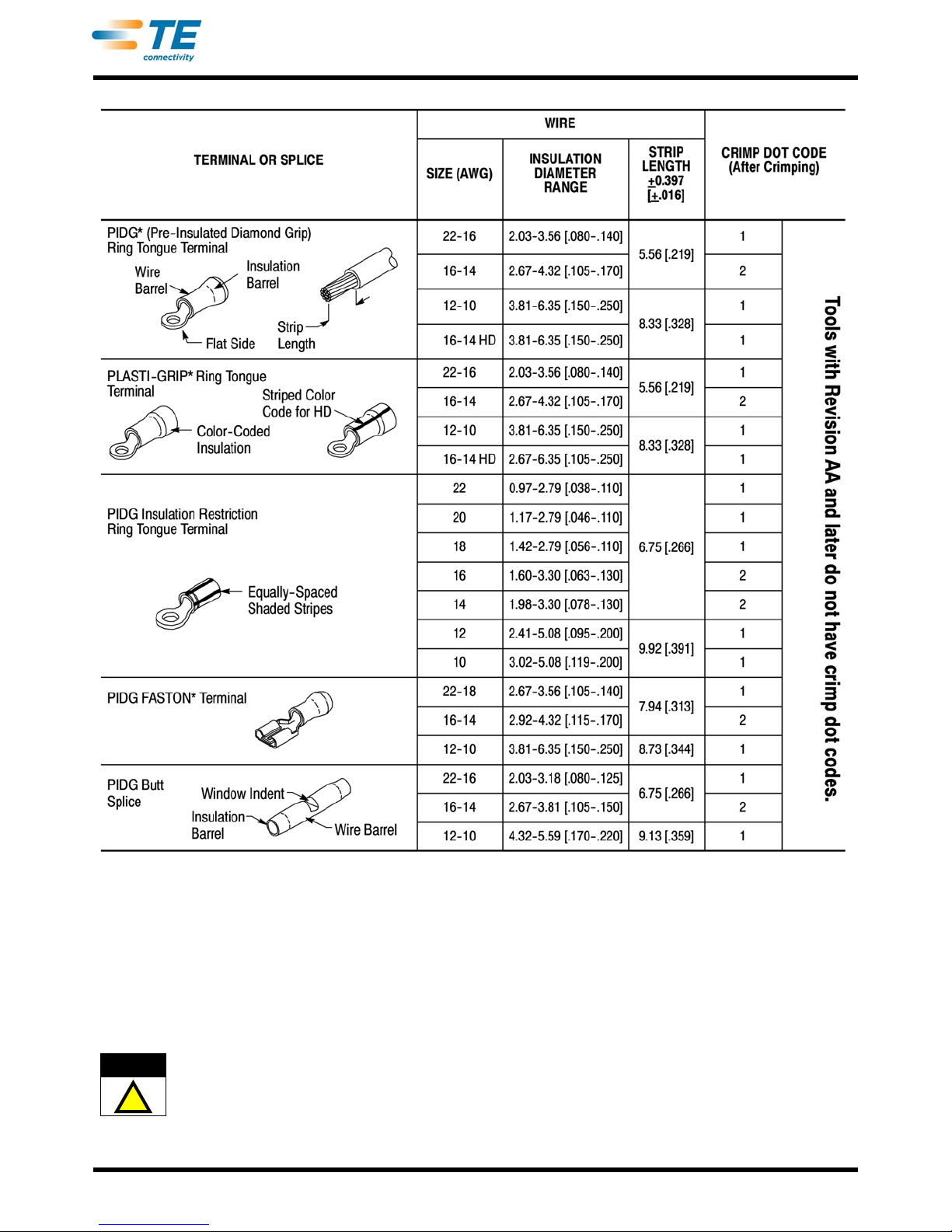
Figure 1
1. INTRODUCTION
TETRA-CRIMP Hand Crimping Tool 59824-1 (shown
in Figure 1) is designed to crimp the terminals and
splices listed in Figure 2 onto stranded wire sizes 22
through 10 AWG. Refer to Catalog 82042 for product
part numbers. Read these instructions thoroughly
before using the hand tool.
Dimensions in this instruction sheet are in
millimeters [with inches in brackets]. Figures and
illustrations are for reference only and are not
drawn to scale.
Reasons for reissue are provided in Section 8,
REVISION SUMMARY.
2. DESCRIPTION
Each hand tool features two crimping dies, a spring-
loaded locator assembly, and a ratchet handle with a
ratchet pawl. See Figure 1.When closed, the dies form
three crimping chambers each labeled by color on the
BACK side of the tool. The color indicates the wire
size and must match the insulation color of the
terminal or splice: yellow (12-10), blue (16-14), red
(22-16), black heavy duty (16-14 HD), and green
(20-16 HD).
The locator assembly positions the terminal or splice
between the crimping dies. The ratchet handle
assures full crimping. Once engaged, the ratchet will
not release until the tool handles have been FULLY
closed, unless the ratchet pawl is depressed to
manually release the ratchet. This feature, when
depressed, prevents crimping of an improperly
positioned terminal or splice.
The crimping dies bottom before the ratchet
releases. This feature assures maximum electrical
and tensile performance of the crimp. Do NOT
re-adjust the ratchet.
3. CRIMPING PROCEDURE
Select the appropriate wire size and terminal or splice
for the hand tool. The wire size and insulation
diameter must be within the specified range for the
terminal or splice. Strip the wire to the dimension
provided in Figure 2. Do NOT nick or cut the wire
strands. Then, proceed as follows:
1. Open the crimping dies by squeezing the tool
handles together until the ratchet releases.
2. Push the locator assembly away from the upper
crimping die slightly and hold.
a. If crimping a terminal, position the wire
barrel in the appropriate crimping chamber
between the locator assembly and the upper
die. Make sure that the flat side of the terminal
faces up. See Figure 3, Detail A.
b. If crimping a splice, position the wire barrel
in the appropriate crimping chamber. Seat the
splice window indent on the locator assembly.
Refer to Figure 3, Detail B.
3. Holding the wire barrel in place, release the
locator assembly.
4. Hold the tool so that the BACK side is facing you,
and insert the stripped wire into wire barrel until the
wire bottoms. Refer to Figure 3.
Crimping
Chamber Label
CrimpingChamber
(3 Places)
Back Side of Tool
Locator
Assembly
Crimping
Dies
Ratchet
Pawl
Ratchet
Handle
NOTE
i
CAUTION
!
ORIGINAL INSTRUCTIONS
408-2823
2of 6
Rev Z
Figure 2
5. Holding the wire in place, squeeze the tool
handles together until the ratchet releases. Allow
the tool handles to open FULLY.
6. Remove crimped terminal or splice from the tool.
7. If crimping a splice, position the uncrimped wire
barrel in the crimping chamber. Make sure to seat
the splice window indent on the locator assembly.
Repeat Steps 3 through 6.
Damaged or worn terminals must not be used.
Terminals may be removed from the wire,
discarded, and replaced with new ones.
4. CRIMP INSPECTION
— Check that the crimp dot code on the color-coded
insulation indicates the crimping chamber used. Refer
to Figure 2.
— Check that the crimp is centered on the wire
barrel. See Figure 4.
— Make sure that the wire insulation does not enter
the wire barrel. See Figure 4.
— Check that the wire end is flush with or slightly
beyond the end of the wire barrel. See Figure 4.
CAUTION
!

408-2823
3of 6
Rev Z
Figure 3
Figure 4
5. MAINTENANCE AND INSPECTION
It is recommended that a maintenance and inspection
program be performed periodically to ensure
dependable and uniform terminations. Though
recommendations call for at least one inspection a
month, frequency of inspection depends upon the
following:
1. The care, amount of use, and handling of the
hand tool.
2. The presence of abnormal amounts of dust and
dirt.
3. The degree of operator skill.
4. Your own established standards.
The hand tool is inspected before being shipped;
however, it is recommended that the tool be inspected
immediately upon arrival at your facility to ensure that
the tool has not been damaged during shipment.
5.1. Daily Maintenance
1. The hand tool should be immersed (handles
partially closed) in a reliable commercial degreasing
compound to remove accumulated dirt, grease, and
foreign matter. When degreasing compound is not
available, tool may be wiped clean with a soft, lint-
free cloth. Do NOT use hard or abrasive objects that
could damage the tool.
2. Make certain that the retaining pins are in place
and that they are secured with retaining rings.
3. All pins, pivot points, and bearing surfaces should
be protected with a THIN coat of any good SAE† 20
motor oil. Do NOT oil excessively.
Back Side
of Tool Upper Die
Stripped
Wire
Wire Barrel
Locator
Assembly
Flat Side of
Terminal
Locator
Assembly
Locator
Assembly
Splice
Window
Indent
Terminal
Splice
Crimp Inspection
Wire Insulation
DoesNotEnter
Wire Barrel Wire End Slightly
Beyond End of
Wire Barrel
Crimp Code (1 Dot Shown)
(Refer to Figure 2)
Crimp Centered
on Wire Barrel
† SAE is a trademark.

408-2823
4of 6
Rev Z
4. When the tool is not in use, keep handles closed
to prevent objects from becoming lodged in the
crimping dies. Store the tool in a clean, dry area.
5.2. Periodic Inspection
A. Lubrication
Lubricate all pins, pivot points, and bearing surfaces
with SAE 20 motor oil as follows:
— Tool used in daily production-lubricate daily
— Tool used daily (occasional)-lubricate weekly
— Tool used weekly-lubricate monthly
Wipe excess oil from tool, particularly from crimping
area. Oil transferred from the crimping area onto
certain terminations may affect the electrical
characteristics of an application.
B. Visual Inspection
1. Close tool handles until ratchet releases and then
allow them to open freely. If they do not open
quickly and fully, the spring is defective and must be
replaced. See Section 6, REPLACEMENT AND
REPAIR.
2. Inspect crimping area for worn, cracked, or
broken dies. If damage is evident, return the tool for
evaluation and repair. See Section 6,
REPLACEMENT AND REPAIR.
C. Ratchet Inspection
The ratchet feature on these hand tools should be
checked to ensure that the ratchet does not release
prematurely, allowing the dies to open before they
have fully bottomed.
1. Squeeze the tool handles together, and count the
number of ratchet stops. Five stops, including the
release position, should be indicated by the
movement of the ratchet pawl and the clicking
sound associated with its movement. Refer to
Figure 1.
2. If fewer positions are indicated, the ratchet pawl
and ratchet handle must be replaced. Refer to
Section 6, REPLACEMENT AND REPAIR.
3. If dies do not bottom after 5 ratchet stops, return
tool for repair. Refer to Section 6, REPLACEMENT
AND REPAIR.
When the tool passes the ratchet inspection, lubricate
it with a THIN coat of any good SAE 20 motor oil.
D. Gaging the Crimping Chamber (Figure 5)
1. Remove traces of oil or dirt from the crimping
chamber and plug gage.
2. In order to properly gage this tool, a terminal must
be crimped in the crimping chamber being
inspected. In place of a terminal, a soft material
such as brass or solder may be used to seat the
tooling.
Figure 5
3. Close the tool handles until the crimping dies
have bottomed; then hold in this position. DO NOT
force the dies beyond initial contact.
4. Hold locator assembly away from crimping dies.
Carefully insert GO element into the corresponding
crimping chamber; do not force it. The GO element
must pass completely through the crimping
chamber.
5. In the same manner, try to insert the NO-GO
element into the same crimping chamber. The NO-
GO element may start entry, but must not pass
completely through the crimping chamber. See
Figure 5.
CRIMPING
CHAMBER
COLOR
CODE
GAGE ELEMENT DIAMETER “W”
(Width)
Max
GO NO-GO
Red 1.981-1.988
[.0780-.0783] 2.181-2.184
[.0859-.0860] 4.69 [.185]
Blue/Green 2.336-2.344
[.0920-.0923] 2.537-2.540
[.0999-.1000] 5.33 [.210]
Yellow/Black 3.251-3.258
[.1280-.1283] 3.451-3.454
[.1359-.1360] 6.85 [.270]
Suggested Plug Gage Design
for Wire Crimping Chamber
Inspection of Wire Crimping Chamber
GO element must pass
completelythroughthewire
crimping chamber only.
NO-GO element may enter
partially, but must not pass
completelythroughthewire
crimping chamber.

408-2823
5of 6
Rev Z
If the crimping chambers conform to the crimping
chamber inspection, the tool is considered
dimensionally correct, and should be lubricated with a
THIN coat of any good SAE 20 motor oil. If not, return
the tool for further evaluation and repair. Refer to
Section 6, REPLACEMENT AND REPAIR.
6. REVISING OLD TOOLS TO SINGLE RATCHET PAWL
Use retrofit kit 2119486-1 for old revision tools with
stamped frames. Use retrofit kit 2119486-2 for old
revision tools with solid frames. Reference Instruction
Sheet 408-10339.
7. REPLACEMENT AND REPAIR
Customer-replaceable parts are listed in Figure 6. A
complete inventory should be stocked and controlled
to prevent lost time when replacement of parts is
necessary. Parts other than those listed should be
replaced to ensure quality and reliability. Order
replacement parts through your TE Connectivity
Representative, or call 1-800-526-5142, or send a
facsimile of your purchase order to 717-986-7605, or
write to:
CUSTOMER SERVICE (038-035)
TYCO ELECTRONICS CORPORATION
PO BOX 3608
HARRISBURG PA 17105-3608
For customer repair service, please contact a TE
Representative at 1-800-526-5136.
8. REVISION SUMMARY
•Updated document to corporate requirements
•Updated table in Figure 6
Figure 6 (Cont’d)
11
12 20
20
11
12 20
20

408-2823
6of 6
Rev Z
Figure 6 (End)
REPLACEMENT PARTS
ITEM PART NUMBER DESCRIPTION QTY PER TOOL
1 310581-1 STOP, Terminal and Wire 1
2 21018-6 NUT, 8-32 2
3 1-21116-0 RING, Retaining 2
4 7-59558-9 PIN, Jaw, Pivot 1
5 --- FRAME, Subassembly 1
6 354266-1 SPRING, Extension 1
7 7-59558-8 PIN, Handle, Retaining 1
8 2217549-1 HANDLE, Plastic 1
9 --- HANDLE, Ratchet 1
10 2217548-1 HANDLE, Plastic 1
11 1583388-1 PAWL, Ratchet 1
12 9-59558-0 PIN, Grooved 1
13 --- PIN 1
14 --- LINK, Toggle 2
15 --- PIN, Toggle Link 2
16 310690-1 SPRING, Extension 1
17 852980-1 LABEL, Vinyl, Five-Color 1
18 18202-1 E-Ring, Bowed 1
19 1-21113-6 E-RING, External 1
20 21045-1 RING, Retaining 2
21 3-21028-8 PIN, Slotted, .094 D.630 L 1
22 --- CRIMPING DIE, Indenter 1
23 --- CRIMPING DIE, Anvil 1
24 2-21002-4 SCREW, Button, 8-32.75 L 2
Table of contents
Other TE Power Tools manuals


Popular Power Tools manuals by other brands


Bosch
Bosch POF 1400 ACE Original instructions

Ingersoll-Rand
Ingersoll-Rand LA428-EU Product information

Certa
Certa CTSMARTIFLA user guide

Chicago Electric
Chicago Electric 67632 Set up and operating instructions

Schulze
Schulze Air press-4 X instruction manual

Chicago Pneumatic
Chicago Pneumatic CP6500 series Operator's manual


