Stingray T3000 Series Instruction Manual

5330 East 25th Street
Indianapolis Indiana 46218
Phone: (888) 445-4142
www.tepid.com
Installation &
Maintenance Manual
Certied to ANSI Z358.1
Stingray Systems
SERIES T3000
Floor Mounted
Emergency
Shower
In order to comply with the ANSI Z358.1 Standard the
following notes should be observed:
• Station should be assembled and installed in accordance
with the manufacturer’s instructions, including flushing fluid
delivery requirements.
• Station should be in accessible locations that require no more
than 10 seconds to reach. The shower station shall be located
on the same level as the hazard and the path of travel shall be
free of obstructions that may inhibit its immediate use.
• Station should be located in an area
identified with a highly visible sign
positioned so the sign shall be visible
within the area served by the station. The
area around the station shall be well lit.
• Shower shall be positioned so that the showerhead is not
less than 82 inches (208.3 cm) nor more than 84 inches
(213.4 cm) from surface on which user stands.
• Shower spray pattern shall have a minimum unobstructed
diameter of 20 inches (50.8 cm) at 60 inches (152.4 cm)
above surface on which user stands, and center of spray
pattern shall be located at least 16 inches (40.6 cm) from
any obstruction.
• If shut off valves are installed in the supply line for
maintenance purposes, provisions shall be made to
prevent unauthorized shut off.
• Refer to ANSI Z358.1 to ensure compliance.
NOTES: It is recommended to ush pipes prior to installing
shower xture. Instructions should be reviewed prior to starting
the installation. Remove parts from packaging and verify all
necessary parts are accounted for and not damaged. Please
contact Stingray Systems for any missing or damaged parts
prior to starting installation.
Stingray Systems recommends that you work safely at all
times and in a manner consistent with the OSHA Lock/Tagout
standard, 29 CFR 1910.147 and other applicable standards.

Installation &
Maintenance Manual
Certied to ANSI Z358.1
INSTALLATION SUPPLIES
Supplies Included:
• Floor Mount Plate P
• Pedestal Pipe (Lower Assembly, Middle Assembly,
Manifold, Solid Pipe, Coupler) P
• Tepid Manifold Assembly P
• Shower Arm Assembly P
• Shower Head P
• Drench Pull Handle P
Supplies Required (Not Included):
• Pipe Sealant or Teflon Tape - To Be Used
On All Piping Connections
• (3) 3/8" Floor Anchors
Specific For Floor Substrate
PEDESTAL INSTALLATION
1. Thread Lower Assembly of 24" pipe to Floor
Base Plate. Thread Middle Assembly of
30" pipe to Lower Assembly. Thread Upper
Assembly of 24" pipe to Middle Assembly.
2. Thread Tepid Manifold Assembly and Solid
Pipe onto partially assembled unit.
3. Thread Shower Arm Assembly into
Tepid Manifold as shown.
4. Position partially assembled unit at final location. Using
the Floor Mount Plate as a template, install floor
anchors (not included) into the floor. Secure partially
assembled unit to the floor with the anchors.
5. Thread Shower Head to the station.
6. Attach Drench Pull Handle by placing Nylon Washer
on each side of outer hole on shower activator arm.
Insert Drench Pull Handle through hole. Lock into
place by inserting Cotter Pins into holes of Drench Pull.
7. Mount sign near (or onto) the assembled
unit at the desired location.
8. Remove Checks from protective wrapping and install on
the Tepid Manifold connection, making sure the arrows
are aligned correctly (pointing toward the assembly).
9. Ensure the activator is pushed upward in the “off”
position. Then, connect 1¼" NPT supply piping to
assembled station. Installer to provide sufficient support
of piping; assembled station should not be relied on as
piping support.
10.
Open supply line to check for leaks. Pull down
on Drench Pull Handle to insure adequate flow
through showerhead. Push up on Drench Pull
Handle to stop water flow from shower.
2
1
2
3
5
6
ABS
Shower Head
Shown
Stainless Steel
Shower Head
Installation &
Maintenance Manual
Certied to ANSI Z358.1
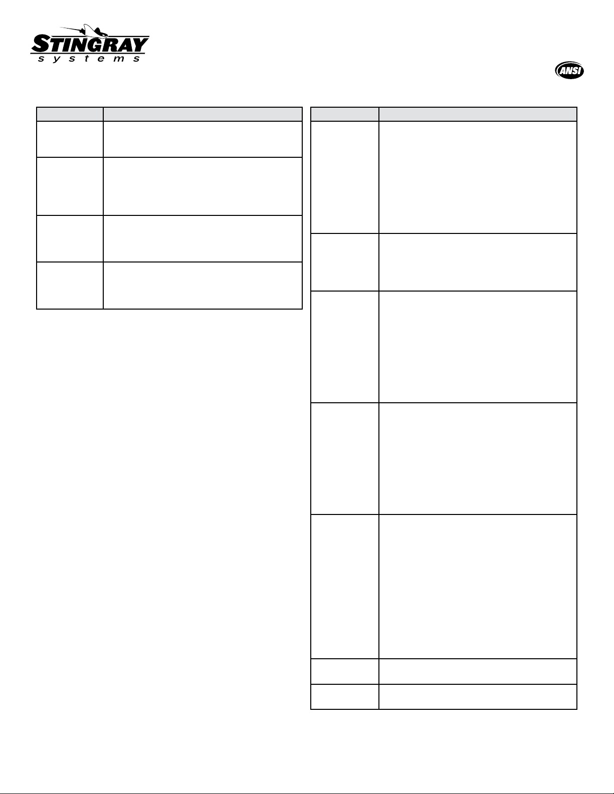
FIXTURE TROUBLESHOOTING
Problem Checklist
No flow. Make sure the water supply for station is on.
Verify checks of Tepid Manifold Assembly
correctly installed.
Water does
not drain
properly.
Check to see if station is installed level and
correct as needed. Double check the main
waste line for the facility. Make sure there is no
blockage and that it can handle the required
drainage.
Water leaks
between
fittings or
connections.
Tighten all connections. If leak persists,
disassemble, apply additional sealant and
reassemble.
Insufficient
flow from
shower head.
Turn water supply to station off. Remove shower
head and clean out any debris. Make sure pull
handle is completely engaged. is fully opened.
Verify pressure to station is at 30 psi as required.
MAINTENANCE
Emergency Shower System shall be activated on a weekly
basis to verify operation and to flush the lines per the
American National Standards Institute (ANSI). Inspections
shall be recorded with inspector’s name and date tested.
Should the need to repair or replace any parts
on this station, please contact Stingray Systems.
Before any repairs are performed, please verify
that the water supply to the station is shut off.
GUARANTEE
We guarantee the Stingray Systems product to be free from
defects in workmanship and material, and for a period of
eighteen (18) months from date of shipment from the factory
or one (1) year from date of installation, whichever occurs
first, will replace any parts found by us to be defective. We
will not be held responsible, however, for any labor incidental
to, or for any damages caused by defective material.
With any questions, please do not hesitate in contacting us
at: 1-888-445-4142 or via email at info@tepid.com.
3
VALVE TROUBLESHOOTING
Problem Checklist
No hot water. Ensure hot water is on. Check pressure at both
inlets. Pressures must be near-equal, or seats will
check and only allow cold water. Need at least
30 psi at both hot and cold inlets. Need at least
a 20 degree difference between hot water and
set temperatures, as well as cold water and set
temperatures. Inspect checks for debris; clean/
replace if needed. Remove thermostat and check
for debris. Make sure liner can move. Clean
thermostat. If continues, replace thermostat.
No cold water. Ensure hot connects to hot side; cold to
cold side. Inspect checks for debris; clean/
replace if needed. Remove thermostat and
check for debris. Ensure liner can move. Clean
thermostat. Replace thermostat if needed.
No water. Ensure hot water is on. Check pressure at both
inlets. Pressures must be near-equal, or seats
will check and only allow cold water. Need at
least 30 psi at both hot and cold inlets. Need at
least a 20 degree difference between hot water
and set temperatures, as well as cold water and
set temperatures. Inspect checks for debris;
clean/replace if needed. Remove thermostat and
check for debris. Ensure liner can move. Clean
thermostat. Replace thermostat if needed.
Insufficient
flow.
Ensure hot water is on. Check pressure at both
inlets. Pressures must be near-equal, or seats
will check and only allow cold water. Need at
least 30 psi at both hot and cold inlets. Need at
least a 20 degree difference between hot water
and set temperatures, as well as cold water and
set temperatures.Inspect checks for debris;
clean/replace if needed. Remove thermostat
and check for debris. Ensure liner can move.
Clean thermostat. Replace thermostat if needed.
Temperature
fluctuation.
Ensure incoming building pressure is not
fluctuating. Inspect supply lines for other
equipment that may be reducing pressure to
the emergency fixtures. Check pressure at both
inlets. Pressures must be near-equal, or seats
will check and only allow cold water. Need at
least 30 psi at both hot and cold inlets. Need at
least a 20 degree difference between hot water
and set temperatures, as well as cold water and
set temperatures. Inspect checks for debris;
clean/replace if needed. Remove thermostat
and check for debris. Ensure liner can move.
Clean thermostat. Replace thermostat if needed.
Leaks around
thermostat.
Remove thermostat and check O-ring. If
damaged or worn, replace/tighten.
Water in
thermostat.
Check connection. Replace thermometer.
Installation &
Maintenance Manual
Certied to ANSI Z358.1
4
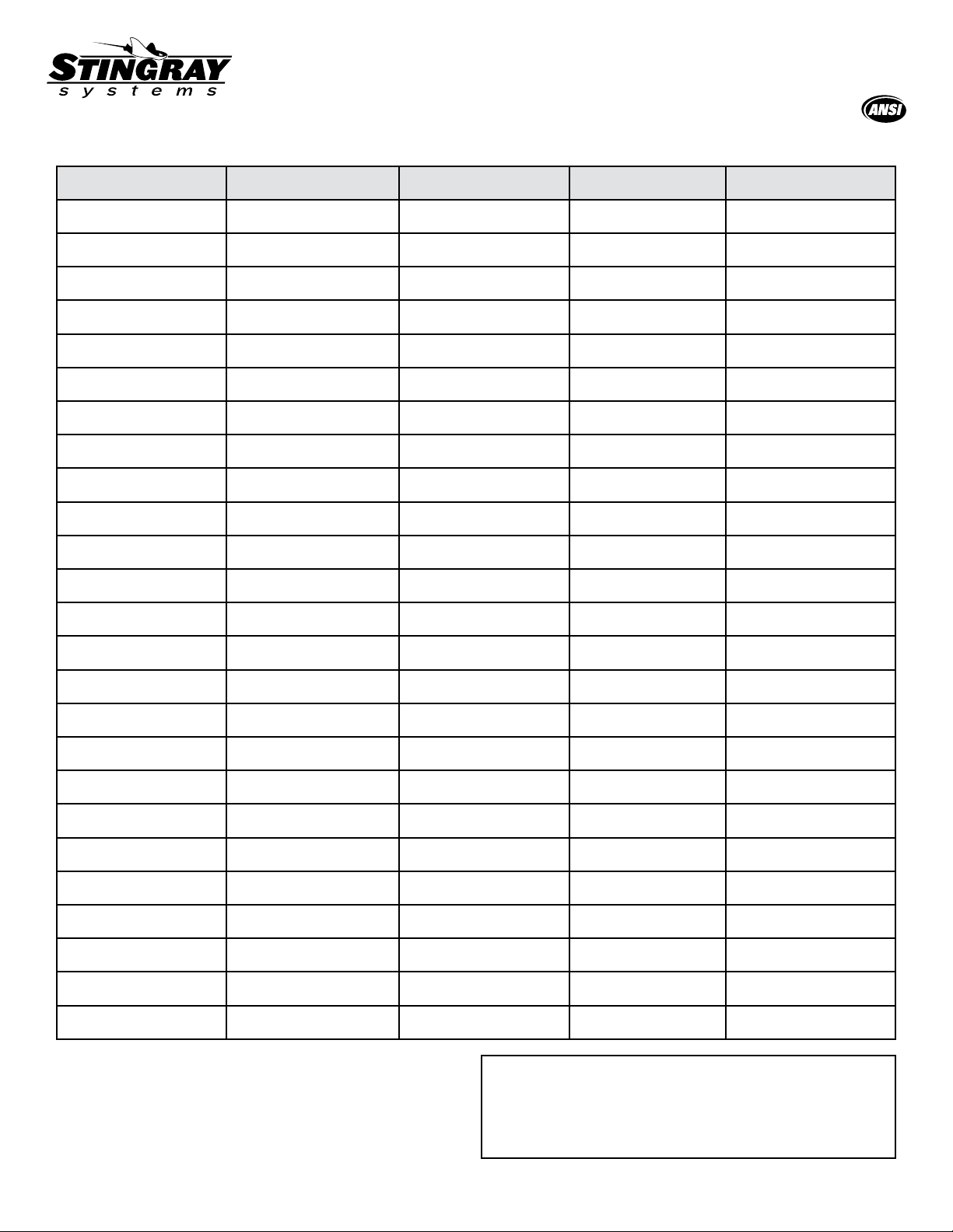
WEEKLY TEST RECORD
Month Test 1 Test 2 Test 3 Test 4
January
February
March
April
May
June
July
August
September
October
November
December
January
February
March
April
May
June
July
August
September
October
November
December
Plumbed emergency eyewashes, eye/face washes, drench
hoses, shower, and combinations systems shall be activated
and tested for a period long enough to verify operation and
ensure that flushing fluid is available.
WARNING: This product contains chemicals known to
the State of California to cause cancer and birth defects or
other reproductive harm. (Installer: California law requires
that this warning be given to the consumer.)
For more information: www.oehha.org/prop65
Other Stingray Bathroom Fixture manuals


