Stingray SV107 Series Instruction Manual
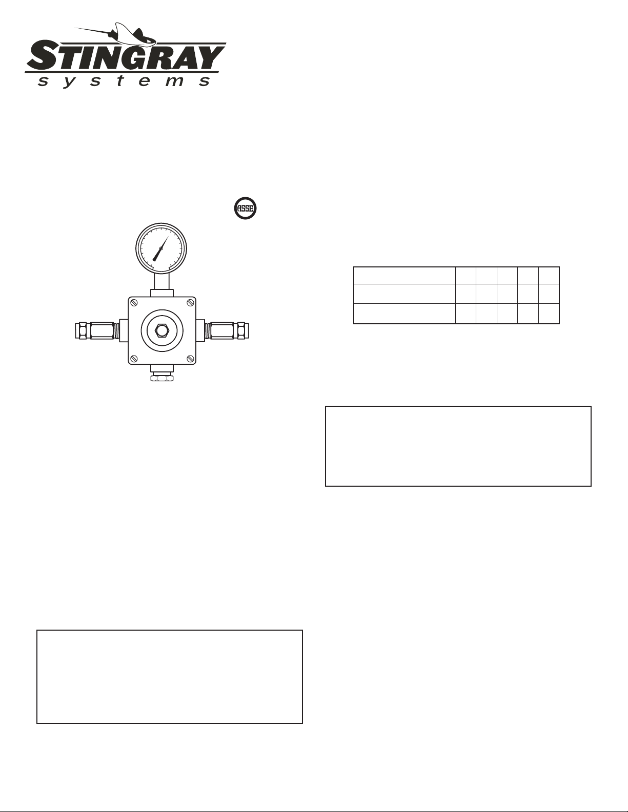
Series SV107
Emergency Eye Wash Valve
(1)
Installation &
Maintenance Manual
M EFV D
Setting the Mixing Valve
Caution: When maintaining and adjusting the mix-
ing valve, all xtures should be isolated from use.
Stingray Systems recommends that you work safely
at all times and in a manner consistent with the
OSHA Lock/Tagout standard, 29 CFR 1910.147
and other applicable standards.
This mixing valve has been set at the factory
to deliver 85°F outlet ow. Should the valve require
adjustment, or an application require a different set
temperature, proceed as follows:
1. Contact the proper medical and safety authorities
to determine the correct water temperature for
the specic application (ie. chemicals).
2. Remove the rounded cover nut on front of the
valve body.
3. Create a draw on the mixing valve by opening a
downstream eye wash xture.
4. Insert a 5/32″ allen key into the stem opening of
the valve and seat in the adjustment screw (not
shown). Set the outlet temperature by turning the
adjustment screw clockwise to reduce tempera-
ture, counterclockwise to increase temperature.
Use the dial thermometer to measure the outlet
temperature.
5. Replace rounded cover nut.
Operating Principle
This Series SV107 Emergency Eye Wash/Face Wash
mixing valve is made of a thermostat element with
a stainless steel sliding piston and liner housed in a
bronze casting. The thermostatic cartridge responds
to temperature changes in the hot and cold water
supplies. In the event the thermostatic element fails
or the hot water supply fails, the valve will provide
full cold water bypass ow.
Note: Valve must be installed with check valves.
If shut off valves are installed in the shower line
for maintenance purposes, provisions shall be
made to prevent unauthorized shut off.
Caution: When maintaining and adjusting the mix-
ing valve, the delivered ushing uid temperature
shall be 60°F (15°C) to 95°F (35°C). In circum-
stances where chemical reaction is accelerated
by ushing uid temperature, a medical advisor
should be consulted for the optimum temperature
for each application.
www.tepid.com
CAPACITIES – MODEL SV107
Pressure Drop PSI 510 20 30 45
Tempered Flow 235710
Cold Water Bypass 12457
30
40
50
60
70 80
90
110
120
130
ASSE 1071 Approved
5330 East 25th Street
Indianapolis Indiana 46218
Phone: (888) 445-4142

(2)
Testing the Mixing Valve
The mixing valve and the emergency xtures it serves
should be tested weekly for proper operation.
Valve temperature test procedure is as follows:
1. Activate eye wash xture to observe and record
the temperature of the dial thermometer. If the
temperature of the thermometer is not correct,
readjust the mixing valve according to the section
“Setting the Mixing Valve”.
2. Observe the ow from the emergency xtures to
ensure an adequate ow of water.
In addition to testing for proper temperature, the cold
water by-pass and hot water shut down features of
the mixing valve should be tested weekly.
The test procedure is as follows:
1. Test valve temperature as described in Step 1
and Step 2 above.
2. Shut off the hot water supply to the mixing valve.
Observe the outlet ow from the emergency x-
tures to ensure an adequate ow of cold water.
A slight drop in ow may occur after shutting
down the hot water supply to the mixing valve;
however, the drop should be minimal and for a
short duration.
3. Open the hot water supply to the mixing valve.
The thermometer should return to the set tem-
perature.
4. Shut off the cold water supply to the mixing valve.
The ow of water should shut down rapidly.
5. Open the cold water supply. The thermometer
should return to the set temperature.
Note: The thermometer should be checked at least
every six months.
Replacing the Thermostat Element
The thermostat replacement procedure is as follows:
1. Shut off the hot water supply and cold water
supply to the mixing valve.
2. Remove the four cover screws (#9) and remove
the front cover (#26) of the valve.
3. Remove thermostat (#11) from the valve body.
No special tools are necessary.
4. Insert a dowel rod, pencil (eraser-end), or narrow
pen into the open end of the thermostat. Push on
the dowel rod with your hand. If the thermostat
feels spongy or springy, the thermostat has lost
its charge. If the thermostat feels solid or hard,
the thermostat is good and operable.
5. Be sure that the stainless steel piston (#15)
moves freely up and down within the liner (#21).
Lime or calcium buildup should be cleaned with
vinegar, green scotch pad, or ne emery cloth.
DIMENSIONS: 1/2″inlets & outlets
Valve
Number A B C
SV107 9″4″8″
30
40
50
60
70 80
90
110
120
130
A
B
C
Note: Gallon per minute ratings may vary de-
pending upon incoming water temperatures and
pressures. Hot and cold water inlet pressures
must be equal.
Provisions shall be made to thermally isolate
the valve.
PRESSURE DROP, POUNDS PER SQUARE INCH
FLOW OF WATER, GALLONS PER MINUTE
70
5
60
40
35
30
25
20
15
8
7
6
9
10
45
50
1 2 3 4 5 6 7 8 9 10 15 20 30 3
5
1/2
≤
MED
CAPACITY OF TYPE SV107
THERMOSTATIC MIXING VALVE
FOR EMERGENCY EYE/FACE WASH
(3)
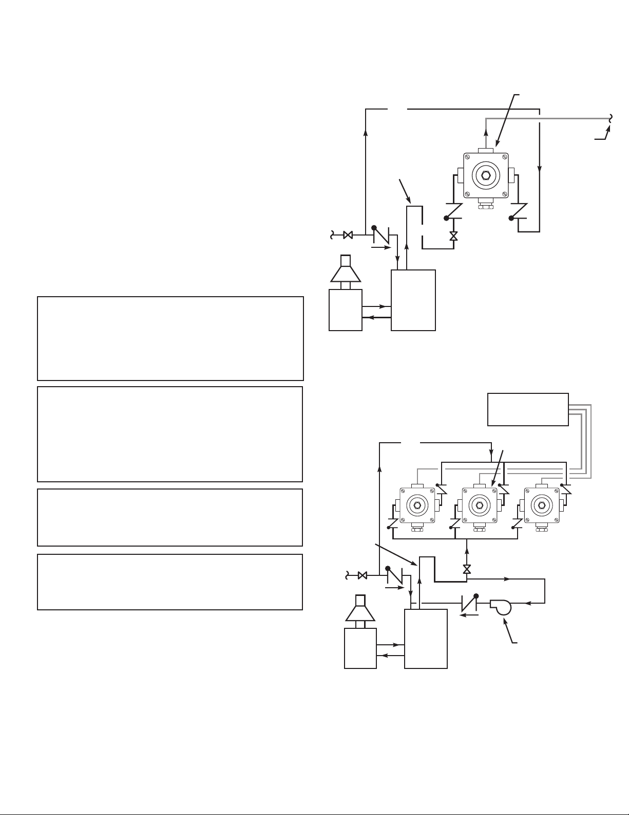
Figure 1
Typical installation. Valve must be
installed with check valves.
Figure 2
Typical installation. Valve must be
installed with check valves.
Installation
After installing the mixing valve, be sure to ush the
system of debris. Stingray Systems recommends
isolation and check valves for proper maintenance.
Typical Installation Figure 1
When installed without a recirculation system:
Install the valve as shown in Figure 1 with the mixing
valve positioned below the hot water tank or heater.
If this is not possible, pipe in heat trap as shown.
Typical Installation Figure 2
When installed with a recirculating pump on the hot
water supply line only:
Note: If the valve is installed 20 feet or more from
the water heater, it is important to recirculate the hot
water supply to the mixing valve.
Install the mixing valve as shown in Figure 2. The
non-circulated loop should be limited to 10 feet and
must be ushed periodically.
Caution: The cold water line must be installed so
that it is not affected by excessively hot ambient
temperatures. Provisions shall be made to ther-
mally isolate the valve. Cold water pipe installed in
the ceilings of boiler rooms or rooms that increase
ambient temperature require a recirculating pump.
GUARANTEE
Note: The mixing valve must be installed with
inlet check valves and the Eyewash/Facewash
xture should be installed 4 to 10 feet from
the mixing valve.
Note: The valve body must be maintained at an
ambient room temperature of above 50°F to pre-
vent premature closure of the safety back-seat
mechanism.
Maximum Inlet Pressure: 125 PSI.
Recommended Supply Pressure: 65 PSI.
Recommended Inlet Temperature: 120°F.*
*When supplying 140°F or greater, additional outlet
controls should be used.
Warning: This product contains chemicals known to the
State of California to cause cancer and birth defects or
other reproductive harm.
(Installer: California law requires that this warning be
given to the consumer.)
For more information: www.oehha.org/prop65
We guarantee the Stingray Systems Mixing Valve to be free
from defects
in workmanship and material, and,
for a period of one year from date of pur-
chase, will replace any parts found by Sting-
ray Systems, to be defective. We will not be held
responsible, however, for any labor incidental to,
or for any damages caused by, defective material.
Each mixing valve is thoroughly inspected and tested
under actual conditions at our factory.
Water
Heater
Storage
Tank
Series SV107
CW
Heat Trap
27” Drop
Recirculating Pump
1 valve per
eye wash fixture
Water
Heater
Storage
Tank
Eye/Face
Wash
Series SV107
CW
Heat Trap
27” Drop
HW

(4)
Date T1
Jan
Feb
March
April
May
June
July
Aug
Sept
Oct
Nov
Dec
Jan
Feb
March
April
May
June
July
Aug
Sept
Oct
Nov
Dec
Jan
Feb
March
April
May
June
July
Aug
Sept
Oct
Nov
Dec
YEAR YEAR
Series SV107 Test Record
Location _______________________
YEAR
Repair Kits and Assemblies
Item Description Contains Part No.
A Repair Kit 11-12-15-18-21+B 79854-00
B O-Ring & Gasket Kit 10-14-17-22-27 79961-00
C Cover Assy. 4-5-10-26 78271-00
D Piston & Liner Assembly 14-15-21-18-17 72904-60
E Thermostat Assy. 10-11-27 78490-00
Parts Break Down
9
26
4
10
5
12
15
25
27
22
14
21
18
11
17
IMM001503
Before you use this chart please make a copy for future testing records.
Popular Plumbing Product manuals by other brands

American Standard
American Standard 7295 Series installation instructions

Tres
Tres Elegance 1.18.103 Technical Characteristics

VIGOUR
VIGOUR DEPSMCH derby plus 185 90 01 quick start guide

American Standard
American Standard Standard 4251S Specification sheet

BELLOSTA
BELLOSTA jeans 4821/N Installation instruction

Hornbach
Hornbach Modell 4 manual


Hans Grohe
Hans Grohe AXOR Steel 35202800 Instructions for use/assembly instructions

Sanela
Sanela SLWN 12 Mounting instructions

Officine Gullo
Officine Gullo ACUTAOG03 L Instructions for installation and use

Pfister
Pfister Zeelan LF-042-ZL Quick installation guide

Aqua
Aqua SAHARA quick start guide

Kohler
Kohler MINIMA K-45805T installation instructions