manuals.online logo
Brands
  1. Home
  2. •
  3. Brands
  4. •
  5. Hornbach
  6. •
  7. Plumbing Product
  8. •
  9. Hornbach Modell 4 User manual

Hornbach Modell 4 User manual

Service-Hotline:+49 421 38693 33
Aufbauanleitung
25832 85767-2008
notice de montage
montagehandleiding
Instrucciones de
construcción
Building Instructions
Istruzioni per il
montaggio
08.02.2010/hell/85440
85767
Vergleichen Sie
zuerst die
Materialliste mit
Ihrem Paketinhalt!
Bitte haben Sie
Verständnis, dass
Beanstandungen
nur im nicht
aufgebauten
Zustand bearbeitet
werden können!
Vergelijk eerst de
lijst van materialen
met de inhoud van
uw pakket!
Reclamaties
kunnen alleen in
behandeling
worden genomen
zolang de
onderdelen nog
niet zijn
gemonteerd!
Veuillez d’abord
comparer la liste
du matériel avec le
contenu de votre
colis ! Nous vous
remercions de bien
vouloir
comprendre que
les réclamations
ne peuvent être
traitées qu’à l’état
non monté !
En primer lugar,
compare la lista de
material con el
contenido del
paquete. Rogamos
entienda que las
reclamaciones
sólo pueden ser
tramitadas antes
montar el objeto.
Firstly compare
the material list
with the contents
of your package!
Please appreciate
that complaints
can be processed
only in the non-
assembled state!
Confrontare la
distinta dei
materiali con il
contenuto del
pacchetto! Le
reclamazioni
potranno essere
accettate
solamente se i
prodotti non sono
ancora stati
montati!
Art.Nr:
Art.-nr.
Art. N°:
N° Art.
Art. no.
Art.N°:
Nr
Nr.
N°
N°
No..
N°.
Bezeichnung
Benaming
Désignation
Denominación
Description
Descrizione
Bild
Afbeelding
Illustration
Dibujo
Illustration
Immagine
Länge
Lengte
Longueur
Long.
Length
Lungh.
Breite
Breedte
Largeur
Ancho
Width
Largh.
Stärke
Dikte
Épaisseur
Espesor
Thick-
ness
Spess.
Material
Materiaal
Matériau
Material
Material
Materiale
Stück
Aantal
Pièce
Ctdad.
Num-
ber
Q.tà
21463 A
Wandbohle Rückwand
Wandplank achterwand
Madrier mural mur arrière
Tablón de la pared posterior
Wall board rear wall
Asse parete posteriore
2231 121 38
Bohle
Plank
Madrier
Tablón
Board
Asse
17
21463 B 2231 121 38 18
26150 C
Wandbohle Seite
Wandplank zijkant
Madrier mural côté
Tablón de la pared lateral
Wall board side
Asse parete laterale
1628 121 38
Bohle
Plank
Madrier
Tablón
Board
Asse
18
26150 E
Wandbohle Front
Wandplank front
Madrier mural façade
Tablón de la pared delantera
Wall board front
Asse della parete frontale
1628 121 38
Bohle
Plank
Madrier
Tablón
Board
Asse
17
26734 D
Wandbohle Front Zuluft
Wandplank front luchttoevoer
Madrier mural façade, aération
Tablón de la pared delantera
entrada de aire
Wall board front air inlet
Asse parete anteriore con
areazione
1628 121 38
Bohle
Plank
Madrier
Tablón
Board
Asse
1
21866 G
Wandbohle Abluft
Wandplank luchtafvoer
Madrier mural, évacuation de l’air
Tablón de la pared salida de aire
Wall board exhaust air
Asse parete con aerazione
2231 121 38
Bohle
Plank
Madrier
Tablón
Board
Asse
1
21431 H
Aufrechte Rahmen
Hoekstijlen
Cadres verticaux
Marco vertical
Upright frame
Telaio verticale
1916 36 36
Rahmen
Raamwerk
Cadre
Marco
Frame
Telaio
3
21814 I 1916 36 36 2
21825 J
Aufrechte Rahmen schräg
Hoekstijlen afgeschuind
Cadres verticaux inclinés
Marco vertical inclinado
Upright frame inclined
Telaio verticale inclinato
1973 36 36
Leiste schräg
Lat afgeschuind
Plinthe inclinée
Listón inclinado
Ledge inclined
Corrente
trapezoidale
2
05.12.2013/hell/85440
Art.Nr:
Art.-nr.
Art. N°:
N° Art.
Art. no.
Art.N°:
Nr
Nr.
N°
N°
No..
N°.
Bezeichnung
Benaming
Désignation
Denominación
Description
Descrizione
Bild
Afbeelding
Illustration
Dibujo
Illustration
Immagine
Länge
Lengte
Longueur
Long.
Length
Lungh.
Breite
Breedte
Largeur
Ancho
Width
Largh.
Stärke
Dikte
Épaisseur
Espesor
Thick-
ness
Spess.
Material
Materiaal
Matériau
Material
Material
Materiale
Stück
Aantal
Pièce
Ctdad.
Num-
ber
Q.tà
56718 K
Brett über Tür
Plank boven deur
Planche dessus de porte
Tabla sobre la puerta
Board over door
Tavoletta sopra la porta
781 38 78
Brett
Plank
Planche
Tabla
Board
Tavoletta
1
21483 M 2159 18 45 2
39129 M 1556 18 45 2
21440 M
Deckenleiste
Deklat plafond
Plinthe de plafond
Listón del techo
Cornice
Correnti del soffitto
880 18 45
Leiste
Lat
Plinthe
Listón
Ledge
Corrente 1
21465 N1
Dachplatte
Dakplaat
Panneau de toit
Placa del tejado
Roof plate
Tavole del tetto
2189 918 55
Vormontiert
Voorgemonteerd
Prémonté
Premontado
pre-assembled
Premontato
1
21482 N2
Dachplatte schmal
Dakplaat smal
Panneau de toit étroit
Placa del tejado
Roof plate narrow
Tavola piccola del tetto
2189 350 55
Vormontiert
Voorgemonteerd
Prémonté
Premontado
pre-assembled
Premontato
1
26152 N3
Dachplatte schräg
Dakplaat afgeschuind
Panneau de toit incliné
Placa del tejado inclinada
Roof plate inclined
Tavola obliqua del tetto
2189 918 55
Vormontiert
Voorgemonteerd
Prémonté
Premontado
pre-assembled
Premontato
1
20527 P
Tür incl. Beschläge
Deur incl. hang- en sluitwerk
Porte, garnitures comprises
Puerta incl. guarniciones
Door including fixtures
Porta, incl. cerniere
1911 815 38
Vormontiert
Voorgemonteerd
Prémonté
Premontado
pre-assembled
Premontato
1
21432 U
Brett Aufrecht
Plank verticaal
Planche verticale
Tabla vertical
Board upright
Asse verticale
2000 18 58
Glattkant
Gladde kant
Angle lisse
Borde liso
smooth-edged
Premontato
2
48541 T
Brett Kranz Front/Seite
Plank kranslijst front/zijkant
Planche couronne devant/côté
Tabla corona delantera/lateral
Board face front/side
Tavoletta marcapiano
anteriore/laterale
2000 17 58
Glattkant
Gladde kant
Angle lisse
Borde liso
smooth-edged
Bordo levigato
2
48543 T
Brett Kranz Seite
Plank kranslijst zijkant
Planche couronne côté
Tabla corona lateral
Board face side
Tavoletta marcapiano laterale
2250 17 58
Glattkant
Gladde kant
Angle lisse
Borde liso
smooth-edged
Bordo levigato
1
48544 T
Brett Kranz über Tür
Plank kranslijst boven deur
Planche couronne dessus de porte
Tabla corona sobre la puerta
Board face over door
Tavoletta marcapiano sopra la
porta
850 17 58
Glattkant
Gladde kant
Angle lisse
Borde liso
smooth-edged
Bordo levigato
1
08.02.2010/hell/85440
Art.Nr:
Art.-nr.
Art. N°:
N° Art.
Art. no.
Art.N°:
Nr
Nr.
N°
N°
No..
N°.
Bezeichnung
Benaming
Désignation
Denominación
Description
Descrizione
Bild
Afbeelding
Illustration
Dibujo
Illustration
Immagine
Länge
Lengte
Longueur
Long.
Length
Lungh.
Breite
Breedte
Largeur
Ancho
Width
Largh.
Stärke
Dikte
Épaisseur
Espesor
Thick-
ness
Spess.
Material
Materiaal
Matériau
Material
Material
Materiale
Stück
Aantal
Pièce
Ctdad.
Num-
ber
Q.tà
48541 Q
Brett Aufrecht 45grad
Plank verticaal 45 graden
Planche verticale 45 degrés
Tabla vertical 45 grados
Board upright 45 degrees
Asse verticale a 45°
2000 17 58
Glattkant
Gladde kant
Angle lisse
Borde liso
smooth-edged
Bordo levigato
2
22044 R
Brett Aufrecht Einstieg
Plank verticaal instap
Planche verticale entrée
Tabla vertical entrada
Board upright entrance
Asse verticale d’ingresso
2000 38 38
Glattkant
Gladde kant
Angle lisse
Borde liso
smooth-edged
Bordo levigato
2
20799 W
Dachverbindungsleiste
Dakverbindingsstrip
Plinthe de raccordement du toit
Listón de unión del tejado
Roof joint ledge
Correnti di collegamento del tetto
1920 3,5 20
Leiste
Lat
Plinthe
Listón
Ledge
Corrente
3
21768 L1a 2156 550 90 2
21833 L1b
Liege
Ligbank
Banc
Banco
Bench
Panca
1610 500 90
Vormontiert
Voorgemonteerd
Prémonté
Premontado
pre-assembled
Premontato
1
20898 L2a 2156 19 90 2
27138 L2b
Liegenblende
Afwerklat ligbank
Rebord banc
Cubierta del banco
Bench covering
Tavola di chiusura della panca
1608 19 90
Leiste
Lat
Plinthe
Listón
Ledge
Corrente
1
40301 L5 555 45 45 3
40302 L6
Liegenhalterung
Ligbankhouder
Support de banc
Soporte del banco
Support for bench
Supporto della panca
1100 45 45
Leiste
Lat
Plinthe
Listón
Ledge
Corrente
2
5512 L9
Stoppklotz
Stopblokje
Taquet de blocage
Bloque de retención
Stop block
Blocchetto di arresto
60 36 36
Leiste
Lat
Plinthe
Listón
Ledge
Corrente
4
15498 O1
Ofenschutz Front Rück
Kachelbeschermrekje voor/achter
Protection de poêle
devant/derrière
Protección del horno lateral
Oven protection front rear
Protezione della stufa anteriore e
posteriore
565 18 95
Brett
Plank
Planche
Tabla
Board
Tavoletta
4
20930 O2
Ofenschutz Seite
Kachelbeschermrekje zijkant
Protection de poêle côté
Protección del horno lateral
Oven protection side
Protezione laterale della stufa
480 18 95
Brett
Plank
Planche
Tabla
Board
Tavoletta
4
24796 O3 800 18 45 2
15493 O6
Ofenschutzstütze
Pootje kachelbeschermrekje
Support de protection poêle
Apoyo protección del horno
Oven protection support
Supporti della protezione della
stufa
800 28 58
Leiste
Lat
Plinthe
Listón
Ledge
Corrente 2
19130 O5
Abluftregelbrett
Plankje regeling luchtafvoer
Planche de régulation de l’air
Tabla reguladora del aire de salida
300 18 95
Brett
Plank
Planche
Tabla
1
13.02.2012/hell/85440
Art.Nr:
Art.-nr.
Art. N°:
N° Art.
Art. no.
Art.N°:
Nr
Nr.
N°
N°
No..
N°.
Bezeichnung
Benaming
Désignation
Denominación
Description
Descrizione
Bild
Afbeelding
Illustration
Dibujo
Illustration
Immagine
Länge
Lengte
Longueur
Long.
Length
Lungh.
Breite
Breedte
Largeur
Ancho
Width
Largh.
Stärke
Dikte
Épaisseur
Espesor
Thick-
ness
Spess.
Material
Materiaal
Matériau
Material
Material
Materiale
Stück
Aantal
Pièce
Ctdad.
Num-
ber
Q.tà
Exhaust air control board
Tavoletta di regolazione della
ventilazione
Board
Tavoletta
26480 O9
Kabelleiste
Afdeklat bedrading
Plinthe à câbles
Listón de cables
Cable cover strip
Listello per i cavi
1825 26 110
Brett
Plank
Planche
Tabla
Board
Tavoletta
1
26285
Spezialschraube außen
Speciale schroef buitenzijde
Vis spéciale extérieur
Tornillo especial fuera
Special screw outer
Vite speciale esterna
4 35
50
26116
Abdeckkappe
Afdekkapje
Capuchon
Tapa
Cover cap
Tappi
50
Beschlagbeutel: Zak met
onderdelen hang-
en sluitwerk:
Sachet
garnitures: Juego de
guarniciones
Bag of
fixtures: Sacchetto
della ferramenta
Art.-Nr.
Art.Nr.
Art. N°
N° Art.
Art. no.
Art. N°
Beschlag
Beslag
Garniture
Guarnición
Fixture
Ferramenta
Größe
Maat
Taille
Dimens.
Size
Dimens.
Bemerkung
Opmerking
Remarque
Observación
Remarks
Nota
Stück
Aantal
Pièce
Ctdad.
Number
Q.tà
3686 4 30 20
3687 4 35 60
21925 4 40 350
3688 4 50 30
9204 4,5 80 25
26715 6 90 80
14014
Spax
Spax-schroeven
Vis Spax
Tornillo Spax
Spax joint
Viti a croce
6 60 20
26285
Spax Kopflochgebohrt
Spax-schroef met kopgat
Vis Spax tête percée
Tornillo Spax cabeza agujereada
Spax joint with drilled access hole
Viti a croce a testa perforata
4,5 40 50
26116
Abdeckkappe
Afdekkapje
Capuchon
Tapa
Cover cap
Tappi
50
14025
Dichtband
Afdichttape
Bande d’isolation
Cinta aislante
Sealing tape
Nastro sigillante
10m
24.06.2013/hell/85440
Art.-Nr.
Art.Nr.
Art. N°
N° Art.
Art. no.
Art. N°
Beschlag
Beslag
Garniture
Guarnición
Fixture
Ferramenta
Größe
Maat
Taille
Dimens.
Size
Dimens.
Bemerkung
Opmerking
Remarque
Observación
Remarks
Nota
Stück
Aantal
Pièce
Ctdad.
Number
Q.tà
22047
Türmagnetset
Deurmagneetset
Set d’aimant de porte
Juego magnético puerta
Door magnet set
Set serratura magnetica della porta
2
14018
Gewindeschraube mit Scheibe und Mutter
Tapschroef met sluitring en moer
Vis filetée avec rondelle et boulon
Tornillo de rosca con arandela y tuerca
Threaded screw with washer and nut
Vite filettata con rondella e bullone
8 70 3
20803
Winkel
Hoekijzer
Équerre
Ángulo
Bracket
Angolare
nur bei Modellen mit 3 Liegen
alleen bij modellen met 3 ligbanken
Seulement pour modèles à 3 bancs
sólo en modelos de 3 bancos
only for models with three benches
solo per i modelli con 3 panche 2
64231 TüV-Schild für Saunaofen
inkl. 4 Schrauben
1
Was mit welchem
Verbindungsmittel
verbunden?
Wat wordt met
welk
verbindingsmiddel
met elkaar
verbonden?
Qu’est-ce qui est
joint ensemble, et
avec quels moyens
de fixation ?
¿Qué se une con
qué elemento de
unión?
What is joined to
what with which
fixture?
Cosa va fissato
con cosa?
Elemente
Elementen
Eléments
Elementos
Element
Elementi
Beschlag
Beslag
Garniture
Guarnición
Fixture
Ferramenta
Stk.
Aant.
Pièce
Ctdad
Number
Q.tà
ins.
Totaal
Total
Total
Total
in tutto
ø
Vorbohrung
Voorge-
boord
Percement
pretaladro
pre-drilling
diameter
foro
Aufrechte Rahmen schräg miteinander (nur bei
Eckeinstieg)
Afgeschuinde hoekstijlen met elkaar (alleen bij
hoekinstap)
Cadres verticaux inclinés ensemble (seulement pour
entrée d’angle)
Marcos verticales inclinados entre si (sólo en entrada
angular)
Upright frames inclined relative to each other
(only for corner entrance)
Telai verticali obliqui tra loro (solo per ingresso ad
angolo)
Spax 4,5 x 80
Spax-schroeven
Vis Spax
Tornillo Spax
Spax joint
Viti a croce
pro Stück
per stuk
par pièce
por unidad
per piece
per ciascun pezzo
5 10
4
Deckenleisten mit Wandelementen
Deklat plafond met wandelementen
Plinthes de plafond avec éléments muraux
Listones del techo con elementos de pared
Cornices with wall elements
Correnti del soffitto con gli elementi delle pareti
Spax 4 x 40
Spax-schroeven
Vis Spax
Tornillo Spax
Spax joint
Viti a croce
pro Leiste
per afdeklat
par plinthe
por listón
per ledge
per ciascun listello
5 25
3,5
08.02.2010/hell/85440
Elemente
Elementen
Eléments
Elementos
Element
Elementi
Beschlag
Beslag
Garniture
Guarnición
Fixture
Ferramenta
Stk.
Aant.
Pièce
Ctdad
Number
Q.tà
ins.
Totaal
Total
Total
Total
in tutto
ø
Vorbohrung
Voorge-
boord
Percement
pretaladro
pre-drilling
diameter
foro
Spax 6 x 90
Spax-schroeven
Vis Spax
Tornillo Spax
Spax joint
Viti a croce
jede 4.Bohle pro
Bohlenende
Elke 4e plank per
plankeinde
tous les 4
madriers par
extrémité de
madrier
cada cuarto tablón
por extremo de
tablón
per board end,
every fourth board
ogni 4 assi, per
ciascuna estremità
dell’asse
2
80 5,5
Wandbohlen mit aufrechte Rahmen
Wandplanken met hoekstijlen
Madrier mural avec cadres verticaux
Tablón pared con marco vertical
Wall board with upright frame
Assi delle pareti con il telaio verticale
Spax 4 x 40
Spax-schroeven
Vis Spax
Tornillo Spax
Spax joint
Viti a croce
pro Bohlenende
per plankeinde
par extrémité de
madrier
por extrremo del
tablón
per board end
per ciascuna
estremità
2 288
3,5
Tür mit Wandelement
Deur met wandelement
Porte avec élément mural
Puerta con elemento de la pared
Door with wall element
Porta con gli elementi delle pareti
Spax 4,5 x 80
Spax-schroeven
Vis Spax
Tornillo Spax
Spax joint
Viti a croce
pro Rahmenseite
per raamwerkkant
par côté de cadre
por lado del marco
per frame side
Per ciascun lato
del telaio
3 6
4
Brett über Tür mit aufrechten Rahmen schräg (nur bei
Eckeinstieg)
Plank boven deur met afgeschuinde hoekstijlen
(alleen bij hoekinstap)
Planche dessus de porte avec cadre vertical incliné
(seulement pour entrée d’angle)
Tabla sobre la puerta con marco vertical inclinado (sólo
en entrada angular)
Board over door with upright frame inclined (only for
corner entrance)
Tavoletta sopra la porta con telaio verticale obliquo (solo
per ingresso ad angolo)
Spax 4x 35
Spax-schroeven
Vis Spax
Tornillo Spax
Spax joint
Viti a croce
pro Seite
per kant
par côté
por lado
per side
per ciascun lato
2 4
3
Dach mit Deckenleisten
Dak met deklatten plafond
Toit avec plinthes de plafond
Tejado con listones del techo
Roof with cornices
Tetto con i listelli del soffitto
Spax 4 x 50
Spax-schroeven
Vis Spax
Tornillo Spax
Spax joint
Viti a croce
pro Dachseite
per dakkant
par côté du toit
por lado del techo
per roof side
per ogni lato del
tetto
3 18
3,5
Ofenschutz
Kachelbeschermrekje
Protection de poêle
Protección del horno
Oven protection
Protezione della stufa
Spax 4 x 35
Spax-schroeven
Vis Spax
Tornillo Spax
Spax joint
Viti a croce
pro Ecke
per hoek
par angle
por esquina
per corner
per ciascun
angolo
2 16
3,5
08.02.2010/hell/85440
Elemente
Elementen
Eléments
Elementos
Element
Elementi
Beschlag
Beslag
Garniture
Guarnición
Fixture
Ferramenta
Stk.
Aant.
Pièce
Ctdad
Number
Q.tà
ins.
Totaal
Total
Total
Total
in tutto
ø
Vorbohrung
Voorge-
boord
Percement
pretaladro
pre-drilling
diameter
foro
Ofenschutzstützen an Ofenschutz
Pootjes aan kachelbeschermrekje
Supports de protection de poêle sur protection de poêle
Apoyo protección del horno a la protección del horno
Oven protection support for oven protection
Supporti delle protezioni della stufa con le protezioni
della stufa
Spax 4 x 35
Spax-schroeven
Vis Spax
Tornillo Spax
Spax joint
Viti a croce
pro Verbindung
per verbinding
par raccord
por unión
per joint
per ogni
collegamento
2 16
3,5
Kabelkanalabdeckung mit Wandelement
Afdekking kabelgoot met wandelement
Canal de couverture des câbles avec élément mural
Cubierta del canal de cable con elemento de la pared
Cable channel covering with wall element
Rivestimento scanalato dei cavi con l’elemento della
parete
Spax 4 x 35
Spax-schroeven
Vis Spax
Tornillo Spax
Spax joint
Viti a croce
nach Bedarf
zo veel als odig
selon le besoin
según la
necesidad
as required
se necessario
bis
tot 4
jusqu’à
hasta
up to
fino a
3,5
Abluftregelbrett an Wand
Plankje regeling luchtafvoer aan de wand
Planche de régulation de l’air sur mur
Tabla de regulación de salida de aire a la pared
Exhaust air control board on wall
Tavoletta di regolazione della ventilazione con la parete
Spax 4 x 50
Spax-schroeven
Vis Spax
Tornillo spax
Spax joint
Viti a croce
1 1
3,5
Türmagnethalter mit Türrahmen
Deurmagneethouder met deurkozijn
Support d’aimant de porte avec cadre de porte
Soporte magnético puerta con marco puerta
Door magnet holder with door frame
Serratura a magnete con lo stipite della porta
Spax 4 x 50
Spax-schroeven
Vis Spax
Tornillo Spax
Spax joint
Viti a croce
pro Stk
per stuk
par pièce
por unidad
per piece
per pezzo
2 4
3,5
Brett aufrecht und Kranzleisten mit Saunakörper
Verticale plank en kranslijst met saunacabine
Planche verticale et plinthes de couronne avec corps du
sauna
Tabla vertical y listones de corona con el cuerpo de la
sauna
Board upright and cornice ledges with sauna body
Asse verticale e listelli del marcapiano con il corpo della
sauna
Spax Kopflochgebohrt mit
Abdeckkappen
Spax-schroef met kopgat
en
afdekkapjes
Vis Spax tête percée avec
capuchon
Tornillo Spax de cabeza
perforada con tapa
Spax joint with drilled
access hole and cover
caps
Viti a croce con foro e tappi
pro Stk
per stuk
par pièce
por unidad
per piece
per pezzo
5 45
4
Liegenhalterungen mit Wand
Ligbankhouders met wand
Supports de banc avec mur
Soporte del banco a la pared
Supports for benches with wall
Supporti delle panche alla parete
Spax 6 x 60
Spax-schroeven
Vis Spax
Tornillo Spax
Spax joint
Viti a croce
pro Halterung
per houder
par support
por soporte
per support
per ciascun
supporto
3 12-15
5,5
Stoppklotz mit Wand
Stopblokje met wand
Taquet de blocage avec mur
Bloque de retención a la pared
Stop block with wall
Blocchetto di arresto con la parete
Spax 6 x 60
Spax-schroef
Vis Spax
Tornillo Spax
Spax joint
Viti a croce
pro Stk
per stuk
par pièce
por unidad
per piece
per pezzo
2
5,5
Winkel an Bank (nur bei Modellen mit 3 Liegen)
Hoekijzer aan bank (alleen bij 3 ligbanken)
Équerre sur banc (seulement sur 3 bancs)
Ángulo al banco (sólo en caso de 3 bancos)
Joining benches (only models with three
benches)
Angolare con le panche (solo per i modelli con 3
panche)
Spax 4 x 30
Spax-schroeven
Vis Spax
Tornillo Spax
Spax joint
Viti a croce
pro Winkel
per hoekijzesr
par équerre
por ángulo
per bracket
Per ogni angolare
8 16
3,5
08.02.2010/hell/85440
Elemente
Elementen
Eléments
Elementos
Element
Elementi
Beschlag
Beslag
Garniture
Guarnición
Fixture
Ferramenta
Stk.
Aant.
Pièce
Ctdad
Number
Q.tà
ins.
Totaal
Total
Total
Total
in tutto
ø
Vorbohrung
Voorge-
boord
Percement
pretaladro
pre-drilling
diameter
foro
Bänke verbinden (nur bei Modellen mit 3 Liegen)
Banken verbinden (alleen bij 3 ligbanken)
Joindre les bancs (seulement sur 3 bancs)
Unir los bancos (sólo en caso de 3 bancos)
Collegamento delle panche (solo per i modelli con 3
panche)
Gewindeschraube mit
Scheibe und Mutter
Tapschroef met sluitring en
moer
Vis filetée avec rondelle et
boulon
Tornillos fileteadores con
arandela y tuerca
Threaded screw with
washer and nut
Vite filettata con rondella e
bullone
3
2
3
2
7
7
08.02.2010/hell/85440
Allgemein:
Bitte beachten Sie, das Sie
sämtliche
Schraubverbindungen
vorbohren müssen, um zu
verhindern das sich das
eingesetzte Holz spaltet.
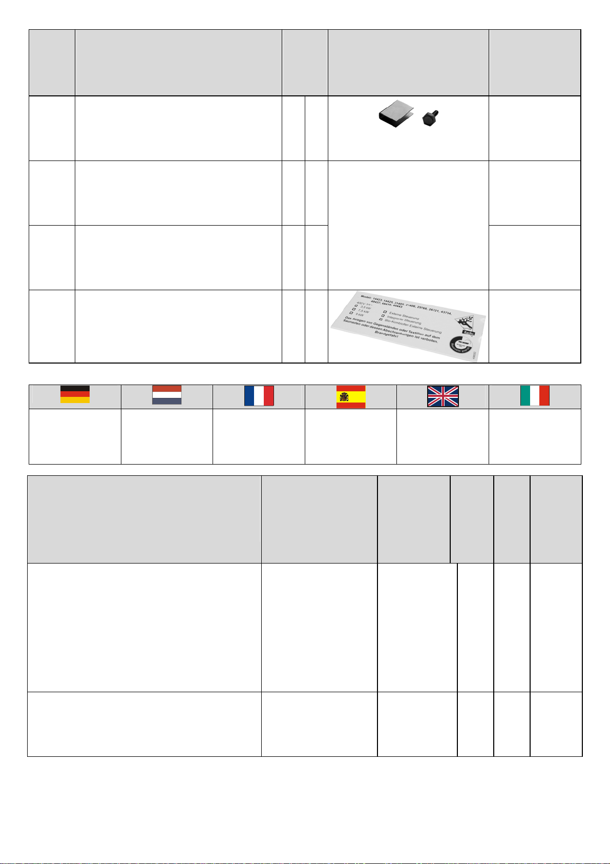
Welches Verbindungsmittel wo
eingesetzt wird entnehmen Sie
der Tabelle: „Was wird mit
welchem Verbindungsmittel
miteinander verbunden?“: Dort
finden Sie auch die
Durchmesser der zu setzenden
Vorbohrungen.
Die Seitenwände sollten mit
Abstand zur Wand montiert
werden, damit man die
Eckverbindung von außen
verschrauben kann. Wenn alle
Seitenwände montiert sind
kann der Saunakörper an die
Wand geschoben werden.
Halten Sie jedoch mindestens
10cm Wandabstand ein, um
eine lange Lebensdauer Ihrer
Sauna zu gewährleisten.
Die Seitenwände müssen mit
der Wasserwaage ausgerichtet
werden. Bitte bauen Sie die
Sauna im rechten Winkel auf.
Durch die Charakteristik Ihrer
Sauna, einzelne Bohlen
übereinanderzuschichten, kann
es zu Höhenunterschieden in
den Wänden kommen. Diese
sind unerheblich, da Ihre
Sauna durch den oberen Kranz
eine einheitliche Höhe erhält.
Algemeen:
Let op dat u alle
schroefverbindingen moet
voorboren om te voorkomen
dat het gebruikte hout splijt.
Welk verbindingsmiddel waar
wordt toegepast, vindt u in de
tabel: „Wat wordt met welk
verbindingsmiddel met elkaar
verbonden?“: Daar vindt u ook
de diameters van de voor te
boren gaten.
De zijwanden moeten op enige
afstand van de muur worden
gemonteerd zodat de
hoekverbinding van buitenaf
kan worden geschroefd. Als
alle zijwanden zijn gemonteerd,
kan de saunacabine naar de
muur worden geschoven. Houd
echter een afstand tot de muur
van ten minste 10 cm om een
lange levensduur van uw sauna
te waarborgen. De zijwanden
moeten m.b.v. een waterpas
worden afgesteld. Zorg ervoor
dat de sauna haaks wordt
opgebouwd.
Door de karakteristieke bouw
van uw sauna met elkaar
overlappende planken kunnen
er hoogteverschillen bij de
wanden voorkomen. Deze zijn
van geen belang omdat uw
sauna door de kranslijst
bovenop een uniforme hoogte
krijgt.
Généralités :
Veuillez observer que vous
devez percer auparavant
l’ensemble des fixations à vis
afin d’éviter que le bois utilisé
ne se fende. Pour savoir quel
moyen de fixation est utilisé à
quel endroit, veuillez consulter
le tableau « Qu’est-ce qui est
joint ensemble, et avec quels
moyens de fixation ? ». Vous y
trouverez aussi le diamètre des
percements à effectuer.
Les murs latéraux devraient
être montés avec une certaine
distance par rapport au mur
pour pouvoir visser le raccord
d’angle de l’extérieur. Lorsque
tous les murs latéraux sont
montés, le corps du sauna peut
être poussé vers le mur.
Laissez cependant une
distance de 10 cm par rapport
au mur afin de garantir une
durée de vie plus longue à
votre sauna.
Les murs latéraux doivent être
dressés à l’aide d’un niveau.
Veillez à construire le sauna en
angle droit. La superposition
des madriers, particularité de
votre sauna, peut provoquer
des différences de hauteur des
murs. Celles-ci sont
négligeables dans la mesure
où la couronne assure au
sauna une hauteur uniforme.
Generalidades:
No olvide que debe preperforar
todas las uniones atornilladas
para evitar que la madera se
abra. De la tabla se desprende
donde se utiliza cada medio de
unión: "¿Qué se une entre sí y
con qué medio de unión?“: Ahí,
usted encuentra también los
diámetros de los pretaladros a
realizar.
Las paredes laterales deberían
montarse con distancia a la
pared para que se puedan
atornillar las uniones de las
esquinas desde fuera. Cuando
se hayan montado todas las
paredes laterales, el cuerpo de
la sauna puede correrse a la
pared.
Si bien, mantenga una
distancia mínima a la misma de
10 cm para asegurar una larga
vida útil de su sauna.
Las paredes laterales se han
de alinear con el nivel de
albañil. Monte la sauna en
ángulo recto.
Por las características de su
sauna, diferentes tablones
sobrepuestos, se pueden
producir diferencias de altura
en las paredes. Éstas carecen
de importancia dado que su
sauna recibe una altura unitaria
por la corona superior.
General:
Please note that it is necessary
to pre-drill all
screw connections in order to
prevent splitting of the wood
used. The table “What is joined
to what with which fixtures?”
here you will also find the
diameters of for the pre-drilling
steps.
The side walls should be
installed at a distance from the
wall, so that the corner joint can
be screwed down from the
outside. When all side walls are
installed, you can push the
sauna up to the wall. However,
maintain a distance of at least
10cm to the wall in order to
ensure a long life for your
sauna.
Align the side walls with the
spirit gauge. Make certain to
erect the sauna strictly
vertically.
Due to the sauna
characteristics, with individual
boards over one another,
differences in the height of the
walls may arise. This is of no
importance, since the upper
face ensures that your sauna
has a uniform height.
Generalità:
Si raccomanda di preforare
sempre prima di avvitare, in
modo da evitare che il legno si
rompa. Nella tabella si può
vedere quali viti ed accessori si
debbano di volta in volta usare
per collegare i pezzi tra loro.
„Quali parti vanno collegate tra
loro e con quali mezzi?”
Vengono indicati anche i
diametri dei fori che si devono
eseguire.
Le pareti laterali non vanno
montate troppo vicino alle
pareti della stanza, in modo da
poter avvitare gli angoli
dall’esterno. Quando tutte le
pareti laterali sono montate il
corpo della sauna può essere
avvicinato alla parete della
stanza. Mantenere almeno 10
cm di distanza dalla parete, per
assicurare una maggiore
durata della sauna.
Le pareti laterali vanno
orientate con la livella a bolla.
Montare la sauna a squadra.
A seconda delle caratteristiche
della Sauna si potrebbero
avere differenze di altezza delle
pareti a seguito del sovrapporsi
delle assi. Ciò è inevitabile, in
quanto la sauna ottiene
un’altezza omogenea con il
marcapiano superiore.
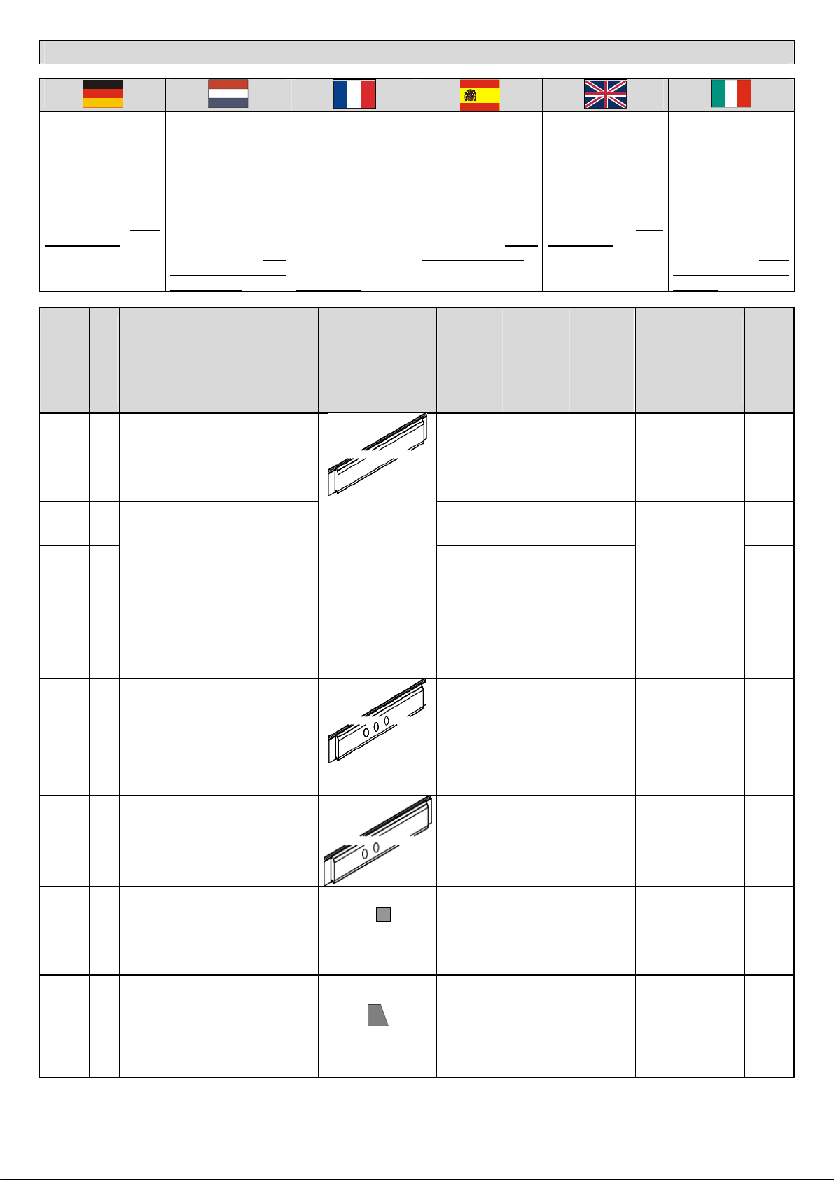
Reihenfolge Aufbau:
Als erstes sollten Sie die
Türscheibe nach anliegender
Anleitung mit dem Türrahmen
verbinden.
Dann folgt die Montage des
Saunagrundkörpers mit
Leistenset sowie Türgriff.
Bauen Sie danach die
Inneneinrichtun
g
wie
Volgorde opbouw:
Als eerste moet de glazen deur
volgens de bijgaande
handleiding aan het deurkozijn
worden bevestigd.
Daarna volgt de montage van
de saunacabine met de
afdeklatten en de handgreep
van de deur. Monteer daarna
de onderdelen van het interieur
Ordre de montage:
Monter d’abord la vitre de la
porte sur le cadre de porte
selon la notice de montage
jointe.
Ensuite vient le montage du
corps du sauna avec le set de
plinthes ainsi que la poignée de
porte. Procéder enfin à
l’assemblage de
Secuencia de montaje:
Primero una la hoja de la
puerta con el marco según las
instrucciones adjuntas.
Después realice el montaje del
cuerpo base de la sauna con el
juego de listones así como la
empuñadura.
Posteriormente monte el
equipo interior, como
Assembly procedure:
Firstly, you should attach the
door plate to the door frame as
described in the accompanying
instructions.
Then assemble the sauna
cabin with the ledge set and the
door handle. This is followed by
the interior equipment, such as
the oven pro
Montare seguendo le
istruzioni:
Per prima cosa fissare il vetro
della porta agli stipiti della
porta, come indicato nelle
istruzioni allegate.
Segue quindi il montaggio del
corpo della sauna, con il set di
listelli e la maniglia della porta.
Quindi arredare l’interno, con la
08.02.2010/hell/85440
Ofenschutz, Liegen usw.
zoals het kachelbeschermrekje,
de ligbanken enz. l’aménagement intérieur tel que
protection du poêle, bancs etc. protección del horno, bancos,
etc tection, benches, etc. protezione per la stufa, le
panche ecc.
Abb.: --> Abbildung Afb.: --> afbeelding Fig.: --> Figure Ilust.: ÆIlustración Fig.: --> Figure Imm. Immagine
Abb.: 1
Hier ist eine bemaßte
Draufsicht dargestellt.
Afb.: 1
Hier is een overzichtstekening
met maten weergegeven.
Fig.: 1
Aperçu général métré. Ilust. : 1
Aquí se representa una vista
en planta dimensionada.
Fig. 1
This figure is a top view
showing the dimensions.
Imm. 1
Qui viene rappresentata una
pianta con le quote.
Abb.: 2
Die Wände bestehen aus 38
mm Blockbohlen (Pos. A-E) mit
Nut und Feder. Diese werden
an den Saunaecken durch Pos.
H untereinander verbunden.
Jede Bohle wird mit 2 Spax an
jedem Ende mit Pos. H
verbunden. Im Bereich der Tür
werden die Frontbohlen mit
Pos.I verbunden. Jede Bohle
wird mit 2 Spax mit Pos. I
verbunden. Beim Schrauben
auf gleiche Höhe der Bohlen
achten. Bitte beim
Saunaaufbau die Sauna immer
überprüfen ob die Sauna im Lot
ist und die Wände rechtwinklig
zueinander verlaufen.
Lage der Pos.D: als 2. Bohle
von unten
Lage Pos. G: in der Rückwand
als 6. Bohle von unten.
Achtung! Bitte jede 4.Bohle mit
den größeren Schrauben
befestigen. dabei mit in die
andere Bohle schrauben
(Detail)
Afb.: 2
De wanden bestaan uit 38 mm
planken (pos. A-E) met veer en
groef. Deze worden bij de
hoeken van de sauna via pos.
H met elkaar verbonden. Elke
plank wordt met 2
spax-schroeven op elk uiteinde
met pos. H verbonden. Ter
hoogte van de deur worden de
voorwandplanken verbonden
met pos. I. Elke plank wordt
met 2 spax-schroeven
verbonden met pos. I Let bij het
schroeven op een gelijke
hoogte van de planken.
Controleer bij de montage van
de sauna altijd of deze in het
lood staat en de wanden haaks
op elkaar staan.
Plaats van pos. D: als 2eplank
van onderen
Plaats pos. G: in de
achterwand als 6eplank van
onderen.
Let op! Bevestig a.u.b. elke 4e
plank met de grotere
schroeven. Daarbij tevens in de
andere plank schroeven (detail)
Fig. : 2
Les murs sont composés de
madriers de 38 mm (pos. A-E)
avec rainure et languette. Ils
sont reliés entre eux aux
angles du sauna par la pos. H.
Chaque madrier est relié à
chaque extrémité à la pos. H
par 2 vis spax. Dans la zone
de la porte, les madriers
frontaux sont assemblés à la
pos. I. Chaque madrier est
assemblé à la pos. I par 2 vis
spax. Veiller à ce que les
madriers soient à une hauteur
identique lors du vissage.
Durant le montage, vérifier
régulièrement que le sauna
est d’aplomb et que les murs
sont tous à angles droits.
Situation de la pos. D : comme
2ème madrier à partir du bas
Situation pos. G : dans le mur
arrière, comme 6ème madrier à
partir du bas.
Attention : Fixer chaque 4ème
madrier avec les vis plus
grosses et visser deux
madriers ensemble (détail).
Ilust.: 2
Las paredes constan de
tablones en bloque de 38 mm
(Pos. A-E) con lengüeta y
ranura. Éstos se unen a las
esquinas de la sauna entre sí
por la posición H.
Cada tablón se une a cada
esquina con Pos. H mediante 2
Spax. En la zona de la puerta,
los tablones delanteros se
unen con la Pos. I. Cada tablón
se une con 2 Spax con Pos. I.
Al atornillar, cerciorarse que los
tablones estén a la misma
altura. Al montar la sauna
comprobar siempre si está
recta y que todas las paredes
formen ángulos rectos.
Situación de la Pos. D: como 2°
tablón desde abajo
Situación de la Pos. G: en la
pared posterior como 6° tablón
desde abajo.
Atención: Fijar cada 4° tablón
con el tornillo más grande. Fijar
este tablón con el otro.
(Detalle)
Fig. 2
The walls consist of 38 mm
block boards (pos. A-E) with
tongue and groove. These are
joined under each other at the
corners of the sauna by pos. H.
Each board is attached with two
Spax joints at each end with
pos. H.
In the area of the door the front
boards are joined with pos. I.
Attach each board with two
Spax joints to pos. I. Make
certain to attach the screws at
the same height to the boards.
When erecting
the sauna, always make certain
that it is standing upright and
the walls are perpendicular to
each other.
Location of pos. D: as second
board from bottom
Location of pos. G: in rear wall
as sixth board from bottom.
Attention! Attach each fourth
board with the large screws.
Drive the screws into the other
board (Detail).
Imm. 2
Le pareti sono fatte di assi da
38 mm (pos. A-E) ad incastro.
Esse vengono collegate tra loro
agli angoli della sauna con gli
elementi in pos. H. Ogni asse
viene fissata con 2 viti a croce
ad ognuna delle sue estremità
con l’elemento H. Nella zone
della porta le assi frontali vanno
fissate all’elemento Pos. I. Ogni
asse va fissta con Pos. I con 2
viti a croce. Nell’avvitare fare
attenzione a che le assi siano
alla stessa altezza. Durante la
costruzione della Sauna
controllare sempre che essa
sia a piombo e che le pareti
siano ad angolo retto tra loro.
Posizione dell’elemento Pos. D:
seconda asse da sotto
Posizione dell’elemento Pos.
G: nella parete posteriore, 6°
asse da sotto.
Attenzione! Ad ogni 4.a asse
utilizzare una vite più grossa
per il fissaggio. Avvitare così
anche nell’altra asse (dettaglio)
Abb.: 3
Alle Bohlen aufschichten und
verschrauben. Bitte auf gleiche
Höhe der einzelnen
Bohlenreihen achten.
Damit die Bohlen fest
aufeinandersitzen mit einem
Gummihammer die Bohlen fest
aufeinander bringen.
Achtung: Die Pos H und I ist
nicht so hoch wie eine fertige
Wand. Im Bereich der Tür Pos.
J anschrauben.
Afb.: 3
Alle planken aanbrengen en
vastschroeven. Let op de
gelijke hoogte van de
verschillende rijen planken.
Om ervoor te zorgen dat de
planken stevig op elkaar zitten
dient u de planken met een
rubberhamer stevig op elkaar
te slaan.
Attentie: pos. H en I zijn niet zo
hoog als een kant en klare
wand. Schroef ter hoo
g
te van
Fig.: 3
Superposer tous les madriers
et les visser. Veiller à ce que
les rangs de madriers
atteignent la même hauteur.
Donner quelques coups de
marteau en caoutchouc afin
d’obtenir une superposition
solide des madriers.
Attention : les pos. H et I ne
sont pas aussi hautes que le
mur terminé. Visser la pos. J
dans la zone de la porte.
Ilust.: 3
Sobreponer todos los tablones
y atonillarlos. Cerciorarse que
todas las líneas de tablones
tengan la misma altura.
Para que los tablones queden
bien fijados unos sobre otros,
ayudarse de una maza de
goma.
Atención: Las Pos H e I no son
tan altas como una pared
terminada. Atornillar Pos. J en
la zona de la puerta.
Fig. 3
Stack all boards and attach
with the screws. Make certain
of the same height in the
different rows of boards.
In order to ensure that the
boards lie firmly over each
other, use a rubber hammer
when laying the boards over
each other.
Attention: Pos. H and I are not
as high as an assembled wall
Screw down in the area of the
Imm. 3
Disporre tutte le assi ed
avvitarle. Controllare che le
singole file di assi siano alla
stessa altezza.
Per fissare bene le assi una
sull’altra farle entrare bene
negli incastri con un martello di
gomma.
Attenzione: Le Pos. H e I non
vanno disposte alla stessa
altezza della parete finita.
Nella zona della
p
orta avvitare
08.02.2010/hell/85440
de deur pos. J vast. door - pos. J. Pos. J.
Abb.: 4
Jetzt wird die fertig montierte
Tür eingesetzt. Mit 3 Stk. Spax
je Seite mit den Fronten
befestigen. Bitte dafür die
Vorbohrungen verwenden und
diese danach mit den
Abdeckkappen des
Beschlagbeutels für die Tür
verschließen. Über der Tür wird
Pos.K montiert und mit 4 Spax
mit den Positionen J
verschraubt.
Pos. M mit je 5 Spax an den
Wänden montieren. Oberkante
Pos. M = Oberkante Pos H.
Darauf das Dichband kleben.
Pos M im Türbereich passend
einkürzen.
Achtung! Unbedingt die Wände
genau ausrichten!
Afb.: 4
Nu wordt de kant en klaar
gemonteerde deur geplaatst.
Met 3 stuks spax-schroeven
per kant aan de voorwanddelen
bevestigen. Gebruik daarvoor
de voorgeboorde gaten en sluit
deze daarna af met de
sierdopjes uit de zak met hang-
en sluitwerkonderdelen voor de
deur. Boven de deur wordt pos.
K gemonteerd en met 4 spax-
schroeven aan pos. J
vastgeschroefd.
Pos. M met telkens 5 spax-
schroeven aan de wanden
monteren. Bovenkant pos. M =
bovenkant pos. H. Plak daarop
het afdichttape.
Pos. M ter hoogte van de deur
pas maken.
Attentie! Stel de wanden
absoluut nauwkeurig af!
Fig.: 4
Installer maintenant la porte
déjà montée. Fixer avec les
parties frontales avec 3 vis
spax par côté. Utiliser les
percements préalables et les
fermer ensuite à l’aide des
capuchons fournis dans le
sachet de garnitures. Au-
dessus de la porte, pos. K est
montée et vissée avec les
positions J avec 4 vis spax.
Monter pos. M sur les murs à
l’aide de 5 vis spax
respectivement. Rebord
supérieur pos. M = rebord
supérieur pos. H. Coller la
bande d’isolation par-dessus.
Ajuster en raccourcissant pos.
M dans la zone de la porte.
Attention ! Les murs doivent
être dressés avec exactitude !
Ilust.: 4
Ahora se coloca la puerta ya
montada. Fijar con los
delanteros con 3 Spax por
lado. Por favor, utilice las
perforaciones previas y
cierrelas posteriormente con
las tapas de la bolsa de
guarniciones para la puerta.
Montar la Pos. K sobre la
puerta y atornillar con 4 Spax
con las posiciones J.
Montar Pos. M con 5 Spax
respectivamente a las paredes.
Borde superior Pos. M = Borde
superior Pos. H. Pegar sobre
ellos cinta aislante.
Acortar Pos M adecuadamente
en el sector de la puerta.
Atención: Es imprescindible
orientar las paredes
exactamente
Fig. 4
Then set in the already
assembled door. Attach the
door frame with three 4.5 x 80
Spax joints to the front on each
side. Use the pre-drilled holes
and close these off afterwards
with the cover caps from the
bag of fixtures for the door.
Pos. K is installed above the
door and attached with four
Spax joints to pos. J.
Install pos. M with five Spax
joints on the walls. The upper
edge of pos. M must be flush
with the upper edge of pos H.
Cover over with sealing tape.
Shorten pos. M in the area of
the door as required.
Attention! Make certain to
exactly align the walls!
Imm. 4
Ora inserire la porta già
montata. Fissare alla parete
frontale con 3 viti a croce per
lato. Inserire le viti nei fori
predisposti e quindi apporre gli
appositi tappi che troverete nel
sacchetto della ferramenta.
Montare Pos. K sopra la porta
ed avvitarlo a Pos. J con 4 viti a
croce.
Montare Pos. M alle pareti con
5 viti ciascuna. Spigolo
superiore dell’elemento Pos. M
= Spigolo superiore
dell’elemento Pos. H. Applicarvi
il nastro sigillante.
Accorciare adeguatamente
Pos. M dalla parte della porta.
Attenzione! Si raccomanda di
orientare le pareti con
precisione!
.
Abb.: 5
Zuerst eine Dachplatte (Pos
N1) auf Deckenleisten
(Dichtband) legen,
Dachverbindungsleiste (Pos W)
in Nut der Dachplatte
einschieben.
Die nächsten Dachplatten (Pos
N2 und N3) einlegen. Die
Dachplatten werden von unten
mit den Deckenleisten
verschraubt.
Afb.: 5
Leg eerst een dakplaat (pos.
N1) op de deklatten
(afdichttape), schuif de
dakverbindingsstrip (pos. W) in
de groef van de dakplaat.
Breng de volgende dakplaat
aan. De dakplaten worden van
onderaf vastgeschroefd aan de
deklatten voor het plafond.
Fig. : 5
Poser d’abord un panneau de
toit (pos. N1) sur les plinthes du
plafond (bande d’isolation),
introduire la plinthe de
raccordement du toit (pos. W)
dans la rainure du panneau de
toit. Poser le panneau de toit
suivant. Les panneaux de toit
sont vissés par le bas aux
plinthes du plafond.
IIust.: 5
Poner primero una placa del
tejado (Pos N1) sobre los
listones del techo (cinta
aislante). Introducir el listón de
unión del tejado (Pos W) en la
ranura de la placa del tejado.
Las placas del tejado se
atornillan por debajo con los
listones del techo
Fig. 5
Firstly lay a roof plate (pos. N1)
onto the cornices (sealing tape)
and push the roof joint ledge
(pos. W ) into the groove of the
roof plate. Lay the next roof
plate.
Screw down the roof plates to
the ceiling ledges from below.
Imm. 5
Dapprima posare una tavola
del tetto (pos. N1) sui listelli del
soffitto (nastro sigillante), quindi
inserire i listelli di collegamento
del tetto (pos. W) nella
scanalatura delle tavole del
tetto. Posare la tavola del tetto
successiva. Le tavole del tetto
vanno avvitate da sotto ai
correnti del soffitto
Pos. U und R und Q werden
mit den Schrauben auf den
Ecken befestigt. An den
Sichtseiten werden die Pos.T
oben bündig mit Pos U, R und
Q angebracht. Diese Leisten
sind länger als benötigt
geliefert. Sägen Sie diese das
bei Ihnen erforderliche Maß.
In der bemaßten Draufsicht
(
Abb.1
)
können Sie
g
enauer
Pos. U en R en Q worden met
spijkers op de hoeken
bevestigd. Aan de zichtzijden
worden de pos. T aan de
bovenkant vlak aanliggend met
pos. U, R en Q vastgespijkerd.
Deze latten zijn met een
universele lengte geleverd.
Zaag deze op de bij u
benodigde lengte.
In het bovenaanzicht met
Fixer les pos. U et R et Q à
l’aide de vis avec capuchons
sur les angles. Aux
emplacements visibles, la pos.
T et les pos. U, R et Q sont
placées jointes à niveau dans
la partie supérieure. Ces
plinthes sont livrées extra-
longues, vous pouvez les
découper à la longueur
nécessaire.
Las Pos. U, R y Q se fijan a las
esquinas con los tornillos con
las tapas. En las partes
visibles, la Pos. T se dispone
arriba y a ras con las Pos U, R
y Q. Estos listones se
suminstran más largos de lo
necesario. Siérrelos a la
medida necesaria.
En la vista en planta medida
(
Ilust. 1
)
, usted
p
uede
Attach pos. U, R and Q with
screws to the corners and
On the visible sides, set pos. T
flush with the upper end of pos.
U , R and Q. These ledges are
delivered longer than
necessary. Saw them to the
required length.
In the top view showing the
dimensions (Fig. 1) you can
reco
g
nize better which led
g
e is
Le Pos. U, R e Q vanno fissate
sugli angoli e dotate di tappi.
Sul lato a vista va fissato
l’elemento Pos. T in modo che
sopra sia a filo con gli elementi
Pos. U, R e Q. Questi listelli
sono più lunghi del necessario.
Segarli nella misura
necessaria.
Nello schema con le quote
(
imm. 1
)
si
p
uò vedere me
g
lio
08.02.2010/hell/85440
erkennen, wie welche Leiste an
die Sauna befestigt wird. maten (afb. 1) kunt u precies
zien hoe elke lat aan de sauna
wordt bevestigd.
Pour voir quelles plinthes sont
fixées au sauna : voir aperçu
métré (fig. 1).
reconocer exactamente con
qué listón se fija a la sauna. attached to the sauna. quale listello va fissato sulla
sauna e come.
Abb.:L1
Hier ist die Lage der
Verschraubungen bei
Liegenhalterung, -führung
sowie Stoppklotz dargestellt.
Achtung, bei der Querliege die
Halterung mit dem Falz nach
unten montieren.
Afb.: L1
Hier is de plaats van de
ligbankhouder en
weergegeven.
Let op, bij de dwarsligbank de
ligbankhouder met de sleuf
naar beneden monteren.
Fig.: L1
Illustration de la position des
vissages du support et du
guidage de banc ainsi que du
taquet de blocage.
Attention, monter le support
avec la rainure vers le bas pour
le banc transversal.
Ilust.: L1
Aquí se representa la situación
de las atornilladuras en el
soporte del banco y del bloque
de retención.
Atención: en el banco
transversal, montar el soporte
con la ranura hacia abajo.
Fig. L1
This figure illustrates the
positions of the screws of the
support for the bench and for
the stop block.
Attention: For the transversal
bench install the holder with the
fold facing downwards.
Imm. L1
Qui è rappresentata la
posizione delle viti per i
supporti e le guide della panca
e per il blocchetto di arresto.
Attenzione, per la panca
trasversale il supporto va
montato con la scanalatura
verso il basso.
Abb.:L2
Liegenhalterungen montieren
Bei der Liegenhalterung der
Querliege die kürzeste
Liegenhalterung verwenden
(wenn vorhanden).
Vertikale Lage / Höhe: Die in
der Zeichnung angegebenen
Maße beachten (Fußboden bis
Unterkante Liegenhalterung
angegeben).
Afb.: L2
Montage ligbankhouders.
Gebruik bij de ligbankhouder
van de dwarsligbank de kortste
ligbankhouder (indien
voorhanden).
Verticale positie / hoogte: zie de
in de tekening aangegeven
maten (vloer tot onderkant
ligbankhouder).
Fig. L2
Monter les supports de bancs.
Pour le support du banc
transversal, utiliser le support
de banc le plus court (si
disponible).
Position verticale / hauteur :
respecter les dimensions de
l’illustration (du sol au bord
inférieur support de banc
indiqué).
Ilust. L2
Montar los soportes del banco.
En el soporte del banco
transversal, utilizar el soporte
más corto (si existe)
Posición vertical / altura:
Respetar las medidas
indicadas en el dibujo (está
indicado del suelo hasta el
borde inferior).
Fig. L2
Assembling the supports for the
benches
For the support for the
transversal bench use the
shortest bench support (if
present).
Vertical position / height:
according to the dimensions
given in the drawing (floor to
lower edge of support for
bench).
Imm. L2
Montare i supporti delle
panche.
Come supporto della panca
trasversale utilizzare il supporto
più breve (se presente).
Posizione verticale / altezza:
Osservare la misura indicata
nel disegno (dal pavimento allo
spigolo inferiore del supporto
della panca).
Abb.:L3
Hier ist die Lage der
Verschraubungen bei
Liegenhalterung, -führung
sowie Stoppklotz dargestellt.
Afb.: L3
Hier is de plaats van de
schroefverbindingen bij de
ligbankhouder en het
stopblokje weergegeven.
Fig.: L3
Illustration de la position des
vissages du support et du
guidage de banc ainsi que du
taquet de blocage.
Ilust.: L3
Aquí se representa las
atornilladuras del soporte y la
guía del banco así como el
bloque de retención.
Fig. L3
This figure illustrates the
positions of the screws for the
bench support, the support
guide and the stop block.
Imm. L3
Qui è rappresentata la
posizione delle viti per i
supporti e le guide della panca
e per il blocchetto di arresto.
Montage der Querliege:
Die Details sind Ansichten der
Liegen von unten!
Montage van de
dwarsligbank:
De details zijn aanzichten van
de ligbanken van onderen
Montage du banc
transversal :
Les détails offrent des vues des
bancs depuis le dessous !
Montaje del banco
transversal:
Los detalles son vistas de los
bancos desde abajo.
Assembling the transversal
bench:
The details are views of the
benches from below!
Montaggio della panca
trasversale:
I dettagli rappresentano la
panca in una prospettiva da
sotto!
Abb.: L5:
Die Befestigung ist leichter,
wenn die Liegeflächen aus den
Liegen während der Montage
herausgenommen werden wie
hier dargestellt.
Afb.: L5:
De bevestiging gaat gemak
kelijker als de
ligbankoppervlakken tijdens de
montage uit de ligbanken
worden gehaald, zoals hier
weergegeven.
Fig. : L5 :
La fixation est plus facile
lorsque les surfaces pour
s’allonger sont retirées des
bancs pendant le montage,
comme représenté ici.
Ilust.: L5
La fijación es más fácil si las
superficies de asiento se sacan
de los bancos durante el
montaje, tal y como aquí se
indica.
Fig. L5:
Attachment is simpler if you
remove the seating from the
benches during installation, as
illustrated here.
Imm. L5:
Il fissaggio è più facile se le
superfici delle panche vengono
estratte dalle panche stesse
per il montaggio, come
rappresentato nell’immagine.
Abb.: L6:
In den Rahmen der Querliege
werden Winkel mit Spax
festgeschraubt. Danach durch
diese Winkel mit den
Schlüsselschrauben die Bänke
Afb.: L6:
In het frame van de
dwarsligbank worden de
hoekijzers met spax-schroeven
vastgeschroefd. Daarna via
deze hoeki
j
zers m.b.v. de
Fig. :L6
Dans le cadre du banc
transversal, des équerres sont
vissées fermement avec des
vis spax. Ensuite, joindre les
bancs entre eux
p
ar le coin à
Ilust.: L6
En el marco del banco
transversal se atornillan
fijamente el ángulo con Spax.
Posteriormente, unir los bancos
p
or la es
q
uina entre sí
Fig. L6:
Attach brackets with Spax
joints in the frame of the
transversal bench. Then join
the benches via the corners
with the la
g
screws, usin
g
these
Imm. L6:
Nella cornice della panca
trasversale avvitare gli angolari
con delle viti a croce. Quindi,
attraverso questi angolari,
colle
g
are le
p
anche tra loro con
08.02.2010/hell/85440
über Eck miteinander
verbinden. Die 3.
Schlüsselschraube setzen Sie
mittig. Die Löcher für die
Schlüsselschrauben müssen
Sie bohren!
Liegen auflegen und vor den
Bänken das Stoppklotz
montieren.
steeksleutels de banken in een
hoek met elkaar verbinden. Het
3eboutje plaatst u in het midden.
De gaten voor de boutjes moet
u eerst zelf boren!
Plaats de ligbanken en monteer
de stopblokjes ervóór.
travers ces équerres avec les
vis à clé. Placer la 3ème vis à
clé au milieu. Vous devez
percer les trous pour les vis à
clé !
Poser les bancs et monter le
taquet de blocage devant les
bancs.
mediante estos ángulos y con
ayuda de los tornillos de llave.
Colocar centradamente el 3°
tornillo de llave. Los agujeros
para los tornillos de llave los ha
de perforar usted.
Colocar los bancos y montar el
bloque de retención delante de
los bancos.
brackets. Place the third lag
screw in the centre. You must
drill the holes for the lag
screws!
Lay the benches and install the
stop block in front.
le viti esagonali lungo l’angolo.
Le 3 viti esagonali vanno poste
nel mezzo. I fori per le viti
esagonali non sono predisposti.
Disporre la panca e fissare il
blocchetto di arresto davanti ad
essa.
Abb.:O1
Ofenschutz montieren Afb.: O1
Montage kachelbeschermrekje Fig. :O1
Monter la protection de poêle.
Ilust.: O1
Montar la protección del horno.
Fig. O1
Install the oven protection.
Imm.: O1
Montare la protezione della
stufa.
Abb.:O2
Bringen Sie die
Ofenschutzstützen an den
Ofenschutz an. Die
angegebenen Maße
gegebenenfalls an den Ofen
anpassen.
Ofenschutz möglichst mittig vor
das Wandelement mit der
Zuluft (Front) stellen.
Schrauben Sie es an diese
Front an. (Beide Bretter die an
der Wand sind anschrauben;
X ... Lage Verschraubung)
Ausnahme: Produktnummer:
85420 dort kommen die
Schrauben in die Schmale
Seite.
Afb.: O2
Monteer de pootjes aan het
kachelbeschermrekje. Pas de
aangegeven maten evt. aan de
kachel aan.
Zet het kachelbeschermrekje
zoveel mogelijk midden vóór
het wandelement met de
luchttoevoer (front). Schroef het
vast aan dit voorwanddeel.
(Beide plankjes die tegen de
wand komen vastschroeven;
X ... plaats schroeven).
Uitzondering: productnummer:
85420, daar komen de
schroeven in de smalle kant.
Fig. : O2
Installer les supports sur la
protection du poêle. Adapter au
poêle les dimensions données
si nécessaire.
Placer le plus possible la
protection de poêle au centre
devant l’élément mural avec
l’aération (façade). Vissez-la
sur cette façade. (Visser les
deux planches du mur ;
X ... position de vissage).
Exception : produit n° 85420,
fixation par vis sur le côté étroit.
Ilust.: O2
Coloque los apoyos de la
protección del horno en la
protección. Adaptar las
medidas indicadas al horno si
es necesario.
Colocar la protección del horno
lo más centradamente posible
delante del elemento de la
pared con la entrada de aire
(delantero). Atorníllela a la
parte delantera. (Atornillar
ambas tablas que están en la
pared; X … posición de
atornillado)
Excepción: número de
producto 85420. Aquí se ponen
los tornillos en la parte
delgada.
Fig. O2
Bring the oven protection
support up to the oven
protection. Adapt the size of the
oven if necessary.
Place the oven protection as
well centred as possible in front
of the wall element with the air
inlet (front) and screw down to
this front (attach both boards
on the wall; X ... position of
screw attachment) Exception:
product number: 85420 - here
the screws are attached from
the narrow side.
Imm.: O2
Fissare i supporti delle
protezioni della stufa alle
protezioni della stufa.
Eventualmente si dovrà
adattare alla stufa le dimensioni
delle protezioni.
Disporre la protezione della
stufa il più centralmente
possibile rispetto all’elemento
della parete con la presa d’aria
(frontale). Avvitarla a questa
parete frontale. (Avvitare
entrambe le assi alla parete ;
X … Posizione viti) Eccezione:
Numero prodotto: 85420 in
questo caso le viti vanno
avvitate sul lato corto.
Kabelleiste:
Wenn Sie die Elektrokabel in
der Sauna vom Ofen zum
Steuergerät und dann zum
Dach verlegen, können Sie mit
der Kabelleiste diese Kabel
abdecken. Die Leiste hat
verschiedene Fräsungen, damit
diese für jede Ofenvariante
angewendet werden kann.
Verwenden Sie die Leiste so
wie Sie diese benötigen.
Afdeklat bedrading:
Als u de snoeren
in de sauna van de kachel naar
de regelaar en vervolgens naar
het dak legt, kunt u achter deze
afdeklat de bedrading
wegwerken. In de lat zijn
verschillende sleuven gefreesd
zodat deze voor elke
kachelvariant kan worden
gebruikt. Gebruik de lat al naar
gelang de gekochte kachel.
Plinthes à câbles:
Si vous posez les câbles
électriques, dans le sauna,
allant du poêle vers l’appareil
de commande et ensuite vers
le toit, vous pouvez recouvrir
ces câbles avec la plinthe à
câbles. La plinthe a plusieurs
fraisages afin de pouvoir être
utilisée pour chaque variante
de poêle. Utilisez la plinthe
comme vous en avez besoin.
Listón para cables:
Si usted coloca el cable
eléctrico en la sauna desde el
horno hasta el aparato de
mando y después hasta el
techo, lo puede cubrir con el
listón de cable. El listón tiene
diferentes fresados para que
pueda utilizarse en todas las
variantes de horno. Utilice el
listón tal y como usted lo
necesita
Cable cover strip:
If you lay the electric cable in
the sauna from the oven to the
control unit and then to the
roof, you can cover the cable
with this cover strip. The cover
strip has different millings, so
that it can be used with
different oven models. Use the
cover strip as required.
Listello per i cavi:
Quando nella sauna si posa il
cavo elettrico che va dalla stufa
al comando e quindi fino al
tetto, rivestire il cavo con il
listello per i cavi. Il listello ha
diverse scanalature, per essere
utilizzabile con i diversi modelli
di stufa. Utilizzare il listello a
seconda delle necessità.
Abb.:O3
Zeichnen Sie die Mitte des
Abluftregelbrettchens an. Dies
ist die Lage der Vorbohrung für
die Schraube. Bohren Sie dort
Afb.: O3
Teken het midden van het
plankje voor de regeling van de
luchtafvoer aan. Hier moet het
g
aat
j
e voo
r
de schroef worden
Fig.: O3
Marquez le milieu de la
planchette de régulation de
l’air. Ceci est la position du
p
e
r
cement
p
our la vis. Percez
Ilust. O3
Marque el centro de la tablita
de regulación de aire de salida.
Ésta es la situación de la
p
erforación
p
revia
p
ara el
Fig. O3
Mark the centre of the exhaust
air control board.
This is the position of the pre-
drillin
g
for the screw. Then
Imm. O3
Segnare il centro della tavoletta
di regolazione della
ventilazione. In quel punto si
dovrà forare la tavoletta
p
er la
08.02.2010/hell/85440
nun vor.
voorgeboord. Boor nu het
gaatje voor. ici un trou avant de visser.
tornillo. Haga aquí la
perforación previa. carry out pre-drilling.
vite. Eseguire il foro.
Abb.:O4
Legen Sie das Abluftregelbrett
mittig über beide
Abluftöffnungen der Rückwand.
Schrauben Sie es nun mit 1
Spax 4 x 30 an.
Afb.: O4
Breng het plankje in het midden
over beide
luchtafvoeropeningen in de
achterwand aan. Schroef het er
nu met 1 spax-schroef 4x30
aan.
Fig.: O4
Posez la planchette de
régulation de l’air au milieu par-
dessus les deux ouvertures
d’écoulement de l’air du mur
arrière. Vissez-la maintenant
avec 1 vis spax 4 x 30.
Ilust.: O4
Coloque la tabla de regulación
de salida de aire en el centro
sobre las aperturas de salida
de aire de la pared posterior.
Atorníllela con 1 Spax 4x30.
Fig. O4
Place the exhaust air control
board in the centre over the two
exhaust air openings on the
rear wall. Then attach, using
one
4 x 30 Spax joint
Imm. O4
Disporre la tavoletta di
regolazione della ventilazione
in mezzo alle due aperture di
ventilazione della parete
posteriore. Avvitarla con una
vite a croce 4 x 30.
Abb.:O5-7
Hier ist die Funktionsweise des
Brettes abgebildet. Regeln Sie
damit die Abluft nach eigenen
Wünschen.
Afb.: O5-7
Hier is de werking van het
plankje afgebeeld. Regel
daarmee de luchtafvoer naar
eigen wens.
Fig.: O5-7
Ceci représente le mode de
fonctionnement de la planche.
Avec elle, régulez l’écoulement
de l’air selon vos désirs.
Ilust. O5-7
Aquí está representada la
forma de funcionamiento de la
tabla. Con ella, usted puede
regular la salida de aire según
su deseo.
Fig. O5-7
This figure shows the functional
principle of the board. Regulate
the exhaust air according to
your own wishes.
Imm. O5-7
Viene illustrato il principio di
funzionamento della tavoletta di
regolazione della ventilazione.
Con essa si può regolare a
piacere la ventilazione.
L1
Ofen
M
T
K
JI
MET
L1
A
Abb.:1
Detail 2
Detail 1
T
E
B
T
H
R
L2
U
U
Q
((2) 85767 Stand 31.05.2005
2194
2193
H
C
H
H
I
I
E
B
B
E
H
E
I
I
C
(3) 85442 / 85439 Stand 26.05.2005
D
Detail 3
Detail 4
Detail 5
Detail 6
Abb.:2
10mm
10mm
10mm
1
1
1
1
4
3
2
4
3
2
4
3
2
4
3
3
2
G
A
6×90
4×40
6×90
6×90
6×90
4×40
E
I
J
H
A
C
(4) 85442 / 85439 Stand 15.07.2004
J
J
E
I
J
Detail 7
Detail 8 Detail 9
Abb.:3
M
M
B
A
M
M
P
K
K
(5) 85442 / 85439 Stand 15.07.2004
Detail 11
Abb.:4
P
J
E
Detail 10
E
1.
2.
4×35
Einbau Glastür
Montage porte en verre
Installation of glass door
Montage van de glazen deur
Montaje de la puerta de cristal
Installazione portello di vetro
01 03–
!!! !!!
N1
T
U
U
T
Q
T
T
RR
(6) 85442 / 85439 Stand 26.05.2005
Abb.:5
Q
Abb.6
N2

Other Hornbach Plumbing Product manuals

Hornbach 10581580 User manual

Hornbach

Hornbach 10581580 User manual

Hornbach 47608-2008 Instruction Manual

Hornbach

Hornbach 47608-2008 Instruction Manual

Hornbach LAMBDA Jungborn 10573812 User manual

Hornbach

Hornbach LAMBDA Jungborn 10573812 User manual

Popular Plumbing Product manuals by other brands

SIMILOR KUGLER arwa-surf WI9.10500.100.001 installation instructions

SIMILOR KUGLER

SIMILOR KUGLER arwa-surf WI9.10500.100.001 installation instructions

Moen EB2000-R installation guide

Moen

Moen EB2000-R installation guide

Kohler K-13960 installation guide

Kohler

Kohler K-13960 installation guide

IKEA ALSVIK AA-291132-2 Assembly instructions

IKEA

IKEA ALSVIK AA-291132-2 Assembly instructions

WATERGUARD Solo installation guide

WATERGUARD

WATERGUARD Solo installation guide

Axor Brushed Nickel 10135821 Specification sheet

Axor

Axor Brushed Nickel 10135821 Specification sheet

CIFIAL 3215005 Assembly and instruction manual

CIFIAL

CIFIAL 3215005 Assembly and instruction manual

Oras 5 Installation and maintenance guide

Oras

Oras 5 Installation and maintenance guide

Sanotechnik BERGEN instruction manual

Sanotechnik

Sanotechnik BERGEN instruction manual

HomLux 063E004435 installation manual

HomLux

HomLux 063E004435 installation manual

Ponte Giulio G12JDS05 Instructions for installation

Ponte Giulio

Ponte Giulio G12JDS05 Instructions for installation

Moen T2442 Series installation guide

Moen

Moen T2442 Series installation guide

Brizo Rook Series installation instructions

Brizo

Brizo Rook Series installation instructions

brondell CleanSpa CSL-40 owner's manual

brondell

brondell CleanSpa CSL-40 owner's manual

Gessi RILIEVO 59023 Bath Mixing Program

Gessi

Gessi RILIEVO 59023 Bath Mixing Program

Omnires Baretti BA7830 Installation and Maintenance

Omnires

Omnires Baretti BA7830 Installation and Maintenance

Kohler K-T609 installation guide

Kohler

Kohler K-T609 installation guide

KWC Plumbing Product Cleaning guide

KWC

KWC Plumbing Product Cleaning guide

manuals.online logo
manuals.online logoBrands
  • About & Mission
  • Contact us
  • Privacy Policy
  • Terms and Conditions

Copyright 2025 Manuals.Online. All Rights Reserved.