STK Professional Audio VP-150 User manual
VP-150
High Impedance Amplifier
OWNER'SMANUAL ENGLISH

2
VP-150
High Impedance Amplifier
Table Of Contents
1.
Introduction ............................................................................................
2
2.
Important Safety Instructions ...............................................................
3
3.
Warranty Information .............................................................................
4
4.
Panel Description ...................................................................................
5
6
Connecting Your System ......................................................................
6-8
7.
Block Diagram ........................................................................................
9
8.
Specification ...........................................................................................
10
ⅠIntroduction
The STK VP-150 is a high technology 5 channel 8 inputs amplifier and state-of-the art performance
designed for Public Address systems such as paging, background music distribution and music
message-on-hold with 100V and 70V line output systems. Also provide 8o ohm low impedance outputs.
The VP-150 is featured oversized high efficient heat sink in a convection cooling and sustained low
impedance capability output stage with power supply. Also FET control special muting circuit which
suppresses unpleasant switch-on noise with lowest in-rush trodial X-Formers.
The VP-150 has attractive front panel with a full complement of LEDs channel input monitoring and output
level condition. And including rack ears for mounting to the 19” standard rack case.
While providing powerful, accurate and reliable performance as well as outstanding value, your STK
amplifier has been designed for many years of dependable duty. Please take the time to read this manual
before operation to fully realize the features and benefits of this fine product.

3
ⅡImportant Safety Instructions
1. Read Instructions- All the safety and operating instructions should be read before the
appliance is operated.
2. Retain Instructions- The safety and operating instructions should be read before
the appliance is operated should be retained for future reference.
3. Heed Warnings- All warnings on this appliance and in the operating instructions should
be adhered to.
4. Follow Instructions- All instructions should be followed.
5. Water and Moisture- This appliance should not be used near water- for example,
near a bathtub, sink, laundry tub, in a wet basement, near a swimming pool, etc.
6. Heat- This appliance should be situated away from heat sources such as radiators,
heat registers, stoves, or other appliances (including amplifiers) that produce heat.
7. Power Sources- This appliance should be connected to a power supply only of the type
described in the operating instructions or as marked on the appliance. if you are not sure
of thetype of power supply to your home, consult your appliance dealer or local power
company. For appliances intended to operate from battery power, or other sources,
refer to the operating instructions.
8. Polarization- If the appliance is equipped with a polarized alternating-current line plug
(a plug having one blade wider than the other), this plug will fit into the power outlet only
one way. This is a safety feature. if you are unable to insert the plug fully into the outlet,
try reversing the plug. if the plug should still fail to fit, contact your electrician to replace
your obsolete outlet. Do not defeat the safety purpose of the polarized plug.
9. Grounding- If the appliance is equipped with a 3-wire grounding-type plug, a plug having
a third (grounding) pin, this plug will only fit into a grounding-type power outlet.
This is safety feature. if you are unable to insert the plug into the outlet, contact your
electrician to replace your obsolete outlet. Do not defeat the safety purpose of the
grounding-type plug.
10. Power Cord Protection- Power supply cords should be routed so that they are not
likely to be walked on or pinched by items placed upon or against them, paying
particular attention to cords at plugs, convenience receptacles, and the point where they
exit from the appliance.
11. Damage Requiring Service- Unplug this appliance from the wall outlet and refer
servicing to qualified service personnel under the following conditions:
a. When the power-supply cord or plug is damaged.
b. If liquid has been spilled, or objects have fallen into the appliance.
c. If the appliance has been exposed to rain or water.
d. If the appliance does not operate normally by following the operating Instructions.
Adjust only those controls that are covered by the operating instructions as an
improper adjustment of other controls may result in damage and will often require
extensive work by a qualified technician to restore the appliance to its normal
operation.
e. If the appliance has been dropped or the cabinet has been damaged.
f. When the appliance exhibits a distinct change in performance-this indicates a need for
service.
12. Servicing- Do not attempt to service this appliance yourself as opening or removing
covers may expose you to dangerous voltage or other hazards.
Refer all servicing to qualified service personnel.

4
ⅢWarranty Information
UNPACKING
As a part of our system of quality
control, every STK product is carefully
inspected before leaving the factory to
insure flawless appearance.
After unpacking, please inspect for any
physical damage. Save the shipping carton
and all packing materials, as they were
carefully designed to reduce the possibility
of transportation damage should the unit
again require packing and shipping.
In the event that damage has occurred,
immediately notify your dealer so that a
written claim to cover the damage can be
initiated with the carrier. The right to any
claim against a public carrier can be
forfeited if the carrier is not promptly
notified and if the shipping carton and
packing materials are not available for
inspection by the carrier. Save all packing
materials until the claim has been settled.
STK Customer Service Department
396-43 CHEONGCHEON-DONG BUPYEONG-GU
INCHEON, KOREA
TEL : +82-(0)31-981-1788
FAX : +82-(0)31-981-1784
E-mail : stkcom@stkpro.com
www.stkpro.com
STK LIMITED 1 YEAR WARRANTY
STK electronics are warranted to be free
from defects in materials and workmanship
under normal use for a period of 1 year
from date of original purchase.
During that period, STK will at its option,
repair or replace materials at no charge if
product has been delivered to STK by a
STK dealer or STK Service Center together
with the original sales receipt or other proof
of purchase. Warranty excludes fuses,
exterior finish, normal wear, failure due to
abuse, or operation outside of specified
ratings. Warranty applies to original purchaser
only. This warranty gives you specific legal
rights which vary from state to state.
For more information about warranty repair,
please contact: Customer Service Dept.,
The STK Professional Audio.
FOR YOUR RECORDS
All of us at STK thank you for your
expression of confidence in STK products.
The unit you have purchased is protected by
a limited 1 year warranty. To establish the
warranty, be sure to fill out and mail the
warranty card attached to your product.
For you own protection, fill out the information below for you own records.
Model Number
Serial Number
Dealer
Date Of Purchase
Salesman
Phone
Other Information
5
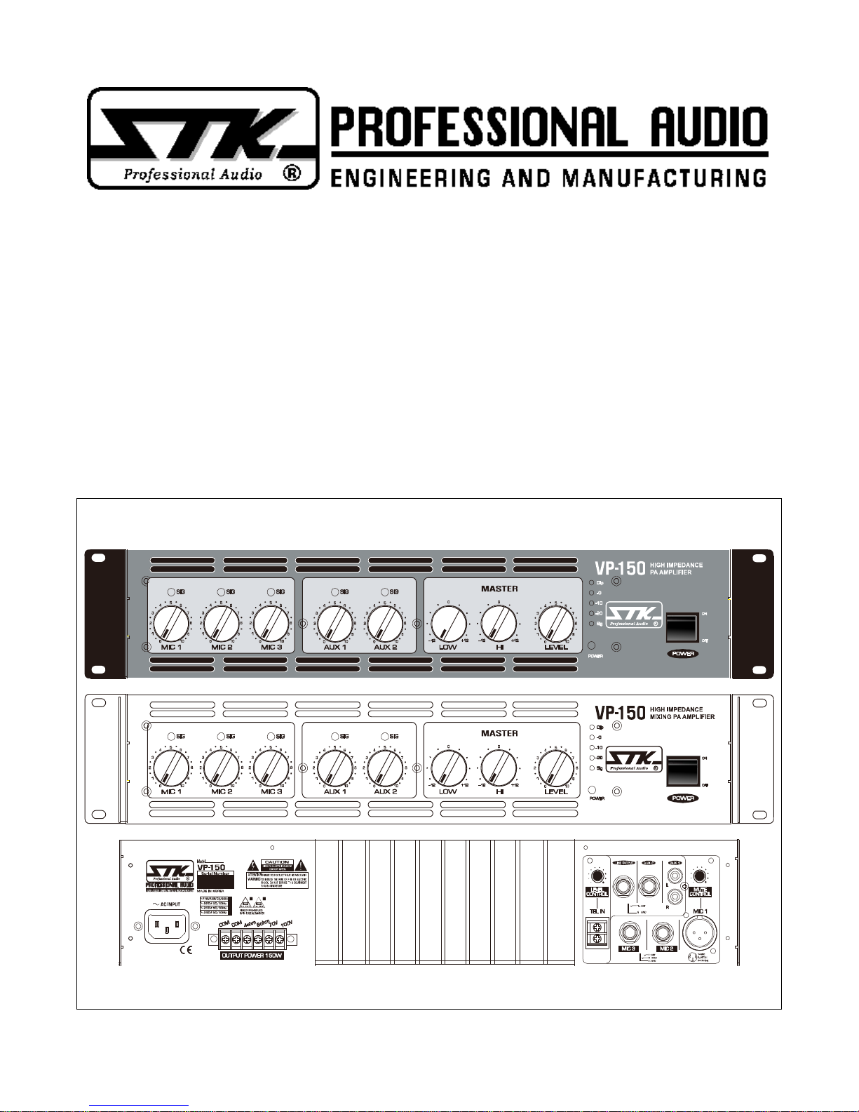
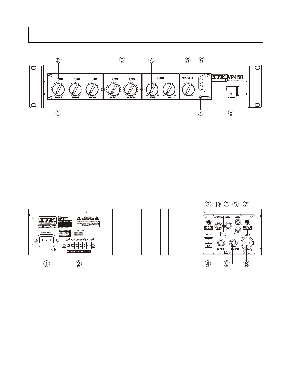
ⅣPanel Descriptions
FRONT PANEL
1. Mic input level Attenuator
Establishes the required input level for each channel.
2. Signal LED
This LED is show driven channel inputs.
3. AUX input level Attenuators
Establishes the required input level for AUXinput channels.
AUX1 is for the cassette deck or CD player.
And AUX2 is for the mixing console or equivalent instruments.
4. Tone Control
The VP-150 can be control LOW and High frequency.
5. Master level Attenuators
This volume control the level of final mixed signal.
6. Output Level Indicator
This level meter indicate the output level.
7. Power Indicator LED
8. Power On/Off Switch
REAR PANEL
AUX 2 AUX 1
1. AC Power Cord
2. Speaker Output terminal
The VP-150 utilize six screw terminal for speaker connection. Two terminals are common output terminals.
Another 4 terminals are 4 ohm, 8 ohm, 70V and 100V output terminals.
For any configuration common terminal will be use with another terminal for speaker connections.
3. TEL Level Attenuators
This volume control the level of telephone paging system signal.
4. TEL Input Terminal
This terminal connect to the telephone paging system.
5. AUX1 Input (RCA, Unbalanced)
These jacks are connect to the CD player or Cassette Deck outputs.
6. AUX2 Input(1/4 "Phone Jacks, unbalanced)
These jacks are connect to the mixing consol outputs
7.Mute Control
A mic 1 input have priority to the other inputsignal. You can adjust the mute level sensitivity.
8. Mic 1 Input Jacks(XLR, Balanced)
9. Mic 2 and 3 Input Jacks (1/4 " Phone Jacks, Balanced)
10. Line Output (1/4 ", unbalanced)
This output is for use to amplifier Input terminal or link connection systems.

6
ⅤConnecting Your System
A. MOUNTING
The VP-150 is designed for standard 19″rack mounting. In addition, the amplifier are provided with sturdy
no-skid rubber feet for secure table top or stacked operation. When rack mounting one or more amplifiers or
when mounting in combination with other equipment, be sure to allow adequate front and rear ventilation to
avoid possible heat related damage to your VP-150 or other rack mounted items.
B. OPERATING PRECAUTIONS
Your STK VP-150 P.A amplifier is well protected from any external faults.
However, we recommend following these common-sense precautions:
1. Safety Instructions
Read and follow all of the safety warnings on page 3 of this manual and on the separate safety precautions
page enclosed with the unit. Do not expose the VP-150 to water or other liquids.
Always unplug the unit if wateris present. Failure to do so can result in injury or death from electric shock.
2. Grounding
If your power amplifier is supplied with a three conductor, grounded power cord and plug, connect the unit
only to a properly grounded mains outlet. Do notuse a ground lift adapter or otherwise attempt to defeat
the ground on the plug. Failure to properly ground the unit can result in damage to the amplifier or other
equipment connected to it and represents a dangerous safety hazard.
3. Line Voltage
Operate from AC mains not more than 5% above or below the specified line voltage. Failure to comply may
invalidate your warranty.
4. Pre-Connection Caution
Always switch off the power and set all the level controls to minimum before making any connections.
This will eliminate any chance of unexpected, loud audio transients that could damage yourspeaker systems.
C. VP-150 OPERATION
1. Input Connections
With the power off, connect your input source lines to channels 1 and 2 on the VP-150.
2. Connect Speaker Systems
Connect speaker systems to speaker outputs as shown figure for low and high impedance output.
The total speaker load for each terminal must be at least minimum impedance value.
3. Level Controls
With all level controls set to 0, switch the power on. Apply a nominal signal to the inputs. The level of the
input signal should be about as high as you will ever need itto be. This way, it will be as far above the
amplifier's noise floor as possible, ensuring as excellent performance signal to noise ratio. Adjust the input
level controls for each channel to achieve the desired maximum listening level or until the sig LEDs flashes
momentarily during program peaks, whichever is lowest. Having set the levels in this manner will render
a clean signal at any level as long as the sig LEDs are not constantly on. Remember, when the sig LEDs constantly
lights, there is distortion present in the amplifier's output section.

7
Connecting Your System
D. INPUT/OUTPUT CONNECTIONS
The STK VP-150 PA amplifier is designed tobe as versatile as possible. The following descriptions of the
input and output connections are designed to help you maximize the unit's potential.
1. XLR Input Jacks
Electronically balanced inputs accepts a standard XLR male connector. Pin1=ground, Pin2=hot or positive(+).
Pin3=cold or negative(-).
2. 1/4'' Phone Input Jacks
Accept an unbalanced line level signal. The unbalanced line uses a normal tip/sleeve connection.
The tip is positive and the sleeve is negative/ground
1. GROUND
(shield)
2. HOT +
3. COLD -
12
3
Tip POSITIVE(+)
Sleeve GROUND(shield)
3. Speaker Outputs
Speaker connections are 6 block screw terminal connectors for Low and High impedance.
Each impedance method provides a safe and reliable connection capable of transferring high power signals if properly
connected. To avoid ANY possible shock hazard, the power amplifier should be disconnected from the AC
power source before making any connections. When connecting your speakers using each method, be sure to
pay close attention to proper polarity. Although connecting your speaker systems out of phase using the wrong
polarity will not damage your speakers, it will affect the quality of sound.When using bare wire connections,
be sure that yourconnections are "clean." If any strands of wire from one connector are allowed to touch the
adjacent connector, damage to your amplifier and sound system could occur.
FIGURE : Low & High Impedance Output
Also be sure above total impedance is less than rated impedance.
NOTE
An amplifiers RMS voltage at rated output may also be determined by
measuring with an RMS voltmeter or calculated using the following formula.
FORMULA : V(RMS) = √Z X √P
where V = RMS voltage in volts
Z = amp rated load impedance in ohms
p = Power rating in walt (RMS)
EXAMPLE 1 : Using the same 150 watt @ 4 ohms amplifier in the preceding example, substitute into the formula as follow.
V (RMS) = √Z X √P
V (RMS) = √4 X √150
V (RMS) = 24.5
When rounded off, the formula indicates an RMS voltage rating of 28 volts.
EXAMPLE 2 : Using the Load impedance at 100V at 150 Watts
V (RMS) = √Z X√P
Z = V X V / P
Z = 100 ² /150 = 66.66 ohm (100V Terminal Minimum Load Impedance)

8
Connecting Your System
E. POWER REQUIREMENTS
Your STK VP-150 is pre-wired at the factory for the correct line voltage(120V or 220-240V) and is furnished
with the appropriate power cord and fuse. If fuse replacement is necessary, always use a fuse with the exact
type and rating as specified on the specifications page of this manual or as indicated on the unit itself.
F. FRONT PANEL INDICATORS
The front panel of the VP-150 has several indicators toalert you to the status of various operating conditions.
Knowing what these indicator LEDs are telling you will help you to use your STK amplifier.
1. Signal LED
A signal LED foreach channel indicates that your signal level is so strong that there is distortion at the output
of that channel. While it is normal for the signal LED to flash during program peaks, the LED should not remain
constantly lit during operation. If it does, most likely you will hear the results in the form of distorted sound
that can be damaging to your speaker systems. In this case, reduce the signal level by lowering the input level
control for the channel that is clipping or reduce the level at the source.
2. Level Meter
A level meter for master stage indicates that your signal level supply to the power output.
If the clip LED constantly lit during operation, most likely you will hear the results in the form of distorted sound that can be
damaging to your speakers systems.
In this case, reduce the signal level by lowering the master level control for the main that is clipping or reduce the level at the
amplifier.
3. Power Indicator LED
The power indicator LED indicates that the power switch is in the on position and that AC mains power is applied.

9
ⅦBlock Diagram

10
ⅧSpecifications
Model
VP-150
Output Power at
1 kHz/THD ≤0.5 EIA
4 ohms
8 ohms
32.5 ohms
66.5 ohms
24.5V
34.7V
70V
100V
T.H.D
f=1 kHz, at rated power
≤0.5%
Frequency response
-3dB, 1Watt Output
100Hz~15 KHz
Signal to Noise Ratio
A-Weighted, RMS
≥95dB
Tone Control
100Hz: +12dB, -12dB 10KHz: +12dB, -12dB
Input Sensitivity
Mic1,2,3: -50dB/Aux 1: -6dB, Aux 2: +4dB/Tel in: 0dB
Input Impedance
≥10k ohm
Cooling
Convection Type
Dimension(W x H x D)
483 x 88 x 295 mm
Weight
Net
23.19Ibs(10.52kg)
Shipping
26.45Ibs(12 kg)
Power Consumption
210 Watts
Fuse
120V: 6A, 220V/230V: 3A
Connector
(Input/Output)
XLR & 1/4“ Input, RCA Jacks, Screw Terminals
Note: Specifications subject to change without notice.
* Protection Circuit : 1) Short Circuit 2) Current Limit 3) Thermal Shut Down
4) Power Up/Down transients 5)AC Line Fuse 6) Limiter
7) DC fault Shut Down 8) RF Protection

11
Notes

12
Owner's Manual for The STK VP-150 High Impedance Power Amplifier.
Printed In Korea APR. 2010 STK-ProfessionalAudio VP150
Table of contents
Other STK Professional Audio Amplifier manuals

STK Professional Audio
STK Professional Audio VS-2004 User manual

STK Professional Audio
STK Professional Audio V-9 User manual

STK Professional Audio
STK Professional Audio V-3.5M User manual

STK Professional Audio
STK Professional Audio VS-15 User manual

STK Professional Audio
STK Professional Audio V-2 User manual

STK Professional Audio
STK Professional Audio VS-15 User manual

STK Professional Audio
STK Professional Audio V-9T User manual

STK Professional Audio
STK Professional Audio VS-25 User manual

STK Professional Audio
STK Professional Audio V-16 Plus 4 User manual

STK Professional Audio
STK Professional Audio V-6 User manual


