STK Professional Audio V-9 User manual
OWNER'S MANUAL
PROTECT
POWER
OUTPUT POWER
450Wx2 / 4 ohm
900W / 8 ohm (Bridge)
10A 250V 20A 250V
1=GND
3=COLD(-)
2=HOT(+)
1=GND
3=COLD(-)
2=HOT(+)
THROUGH
900W / 8 ohm(Bridge)
CH 2 CH 1
900W / 8 ohm
450W / 4 ohm
300W / 8 ohm
450W / 4 ohm
300W / 8 ohm
CH 1
CH 1
CH 2
CH 2
CH 1
CH 2
CH 1
CH 2
1=GND
3=COLD(-)
2=HOT(+)
1=GND
3=COLD(-)
2=HOT(+)
THROUGH
OUTPUT POWER
300Wx2 / 4 ohm
600W / 8 ohm (Bridge)
600W / 8 ohm(Bridge)
CH 2 CH 1
600W / 8 ohm
300W / 4 ohm
210W / 8 ohm
300W / 4 ohm
210W / 8 ohm
CH 1
CH 1
CH 2
CH 2
CH 1
CH 2
CH 1
CH 2
사용설명서
V-9
/ V-6
2 채널 파워 앰플리파이어
2 Channel Power Amplier

2
1. Introduction
l
제품 소개
V-9/V-6
2 Channel Power Amplier l2채널 파워 앰플리파이어
Table of Contents
l
목 차
1. Introduction l 제품 소개........................................................................................................................................
2
2. Important Safety Instructions l 안전을 위한 주의 사항.....................................................................
3
3. Panel Description l 각 부의 명칭 ....................................................................................................................
5
4. Operate Your System l 시스템 동작하기....................................................................................................
8
5. System Hookup Diagram l 시스템 연결 구성도.....................................................................................
14
6. Block Diagram l 회로의 구성도.........................................................................................................................
16
7. Specications l 제품 규격...................................................................................................................................
17
8. Warranty Information l 제품 보증에 대해서 ..............................................................................................
19
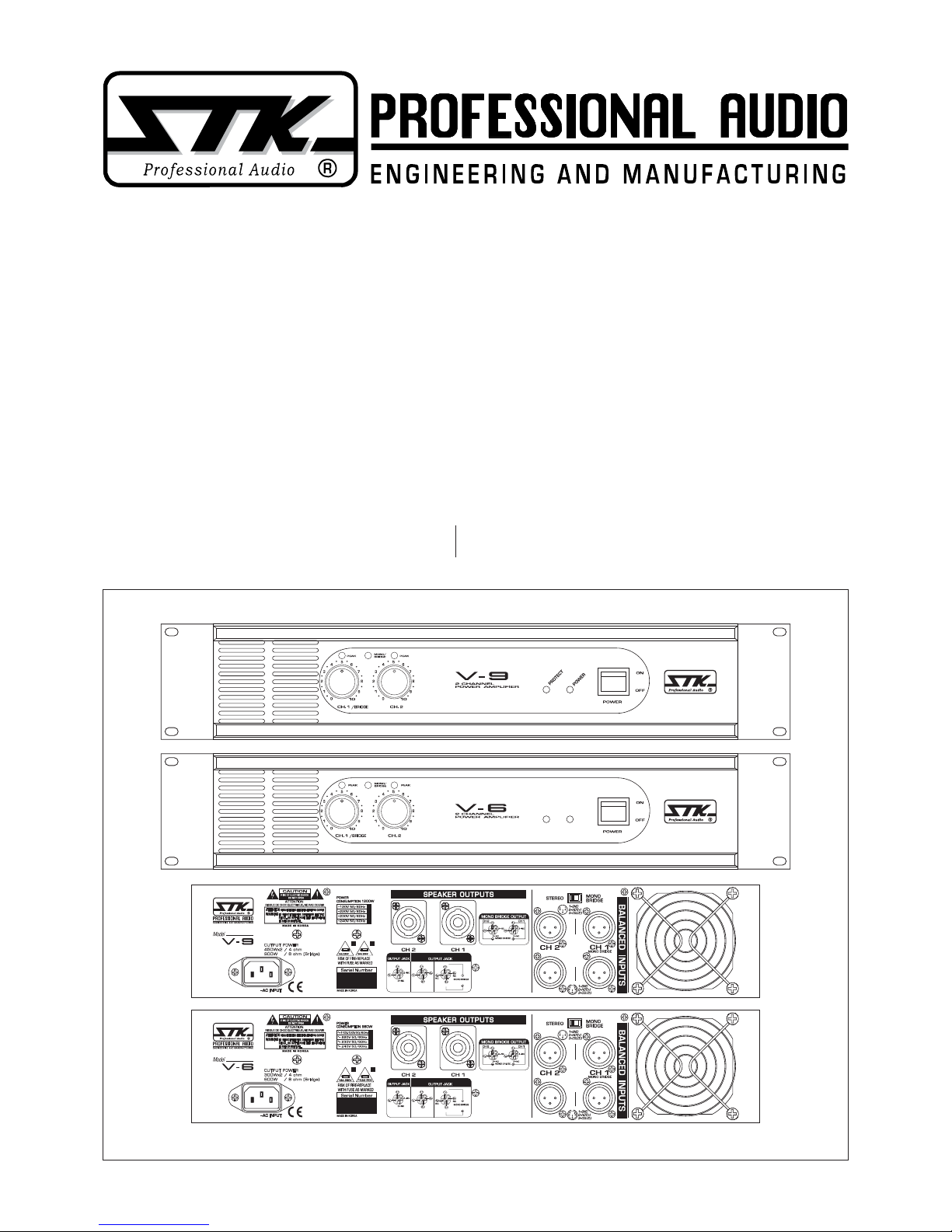
STK V-9 스테레오 파워 앰프는 고효율 트로이덜 트랜
스포머를 사용하여 저역 연속 출력시 최고의 힘을 갖추도
록 설계 되었으며 어떠한 장소에서도 운용이 가능한 우수
한 Professional Sound 시스템의 설치와 사용을 위해 설
계된 최신 성능의 고품질 제품입니다.
V-9와 V-6 파워 앰프는 제품 후면의 스위치로 2 채널/
STEREO 모드와 고출력 모노 브릿지 방식 으로 앰프의
출력 상태를 조건에 따라 선택하여 사용하실 수 있습니
다.
V-9/V-6 파워 앰프는 열악한 조건에서도 트러블 없는
안정된 동작을 기하기 위해 턴넬 냉각 방식의 대용량 힛
트싱크를 채택하고 있으며 냉각팬의 속도를 출력대비 온
도상승에 비례하여 동작시키도록 되어있습니다. 또한 표
시등을 적용한 멋진 전면부는 제품의 동작상태와 기능을
알기 쉽도록 설계되어 있습니다.
더욱 뛰어나고 정확하며 믿을만한 성능을 제공하기 위
해서 STK V시리즈는 수년간의 연구를 거듭하여 설계되
었습니다. 제품을 동작시키기 전에 이 사용설명서를 꼭
읽어보시고 이해하시어 올바르게 제품을 사용해 주시길
바랍니다.
The STK V-9 and V-6 are a high quality, 2 Channel
power ampliers featuring state-of-the-art performance
designed for professional sound reinforcement and
installation use.
The V-9 and V-6 are a stereo amplier that can also be
used for high level monophonic performance by making
use of the bridge mode.
The V-9 and V-6 feature oversized heat sinks in a
wind tunnel cooling system with variable speed fans
for trouble free operation under the most adverse
conditions. In addition, the V-9 and V-6 have attractive
front panels with a full complement of LEDs to monitor
functions and performance level conditions. While
providing powerful, accurate and reliable performance
along with outstanding value, your STK V-9 and V-6
power amplier have been designed for many years of
dependable service. Please take the time to read this
manual before operation so that you fully understand the
features and correct use of this exceptional product.

3
Ⅰ Introduction
l
제품 소개
1. 사용 설명서를 꼭 읽어주세요
제품을 사용하기 전에 본 설명서의 안전과 작동에 관한 모든 기능
설명들을 반드시 읽어 보십시오.
2. 사용 설명서를 잘 보관하세요
안전과 작동에 관한 설명은 나중에 참고하게 될 경우가 있으므로
잘 보관해서 유용하게 사용하십시오.
3. 주의 및 경고사항
사용 설명서에 나타나 있는 모든 주의사항들은 반드시 지켜야 합니
다.
4. 사용법을 지켜주세요
본 설명서의 사용법에 관한 모든 내용들은 반드시 지켜야 합니다.
5. 수분과 습기주의
제품은 물기 또는 습기가 많은 곳에 설치하면 감전의 원인이 됩니
다. (욕조, 세면기, 부엌, 세탁기, 젖은 바닥, 수영장의 풀 근처, 습
지 등)
6. 열주의
제품은 전열기구 혹은 열을 발생하는 그 밖의 기구들로부터 떨어진
곳에 설치되어야 합니다. 설치 전 반드시 주변을 확인하시어 건조
한 장소에 제품을 설치해 주십시오.
7. 전원주의
이 제품은 반드시 사용 설명서에 정해진 타입의 전원 또는 본체에
표시된 전원에 연결되어야 합니다. 만약 사용하려는 전원이 확실치
않을 때는 전원 기구 판매자나 전원 공급자에게 문의하세요. 공급
되는 전원이 축전지 형태이거나 다른 방식이라면 제품 사용을 피해
주세요.
8. 분극 플러그에 대한 주의
만약 전원기구가 극성이 있는 교류전원이라면(플러그 중 한 블레이
드가 다른 것에 비해 넓게 되어 있습니다.) 이 플러그는 오직 한 가
지 방법으로 전원 아울렛에 끼워져야 합니다. 이것이 안전한 모습
입니다. 만약 플러그를 올바르게 끼울 수 없다면 플러그를 빼고 다
시 시도해 보세요. 만약 그래도 안 된다면 전원 아울렛을 교체하도
록 전기 기사에게 문의하세요. 분극 플러그에 대한 주의사항을 반
드시 지켜주세요.
9. 접지 플러그에 대한 주의
만약 전원기구가 3선 접지 타입의 플러그라면 세번째핀(접지핀)을
가지고 있을 것입니다. 이 플러그는 반드시 접지 타입 전원 아울렛
에 맞게 끼워져야 합니다. 이것이 안전한 모습입니다. 만약 이 플러
그를 전원아울렛에 올바르게 끼울 수 없다면 전원 아울렛을 교체하
도록 전기기사에게 문의하세요. 접지 플러그에 대한 주의사항을 반
드시 지켜주세요.
10. 전원 코드의 보호
전원 공급 코드는 플러그, 콘센트, 그리고 본 제품과 연결되는 지점
들에 특별한 주의를 기울이면서 정확한 방향으로 꽂혀야 합니다.
그렇지 못한 경우에는 화재 및 제품 손상의 원인이 될 수 있습니다.
2. Important Safety Instructions
l
안전을 위한 주의 사항
1. Read Instructions
All the safety and operating instructions should be read before
the appliance is operated.
2. Retain Instructions
The safety and operating instructions should be retained for
future reference.
3. Heed Warnings
All warnings on this appliance and in the operating
instructions should be adhered to.
4. Follow Instructions
All instructions should be followed.
5. Water and Moisture
This appliance should not be used near water- for example,
near a bathtub, sink, laundry tub, in a wet basement, near a
swimming pool, etc.
6. Heat
This appliance should be situated away from heat sources such
as radiators, heat registers, stoves, or other appliances (including
ampliers) that produce heat.
7. Power Sources
This appliance should be connected to a power supply only
of the type described in the operating instructions or as
marked on the appliance. If you are not sure of the type of
power supply to your home, consult your appliance dealer
or local power company. For appliances intended to operate
from battery power, or other sources, refer to the operating
instructions.
8. Polarization
If the appliance is equipped with a polarized alternating-
current line plug (a plug having one blade wider than the
other), this plug will t into the power outlet only one way.
This is a safety feature. If you are unable to insert the plug
fully into the outlet, try reversing the plug. If the plug should
still fail to t, contact your electrician to replace your obsolete
outlet. Do not defeat the safety purpose of the polarized plug.
9. Grounding
If the appliance is equipped with a 3-wire grounding-type
plug, a plug having a third (grounding) pin, this plug will only
t into a grounding-type power outlet. This is safety feature.
If you are unable to insert the plug into the outlet, contact
your electrician to replace your obsolete outlet. Do not defeat
the safety purpose of the grounding-type plug.
10. Power Cord Protection
Power supply cords should be routed so that they are not
likely to be walked on or pinched by items placed upon or
against them, paying particular attention to cords at plugs,
convenience receptacles, and the point where they exit from
the appliance.

4
Ⅰ Introduction
l
제품 소개
11. Damage Requiring Service
Unplug this appliance from the wall outlet and refer servicing
to qualied service personnel under the following conditions:
a. When the power-supply cord or plug is damaged.
b. If liquid has been spilled, or objects have fallen into the
appliance.
c. If the appliance has been exposed to rain or water.
d. If the appliance does not operate normally by following
the operating Instructions. Adjust only those controls
that are covered by the operating instructions as an
improper adjustment of other controls may result in
damage and will often require extensive work by a
qualied technician to restore the appliance to its normal
operation.
e. If the appliance has been dropped or the cabinet has
been damaged.
f. When the appliance exhibits a distinct change in
performance-this indicates a need for service.
12. Servicing
Do not attempt to service this appliance yourself as opening
or removing covers may expose you to dangerous voltage
or other hazards. Refer all servicing to qualied service
personnel.
11. 제품 손상 수리 서비스
본 제품에 다음과 같은 경우가 발생했을 때, 전문가에 의해서만 수
리를 받을 수 있습니다.
가. 전원공급 코드 혹은 플러그가 손상되었을 경우.
나. 제품 안으로 이 물질이 떨어졌거나 액체가 스며들었을 경우.
다. 제품이 빗물이나 물에 젖었을 경우.
라. 제품이 정상적으로 작동하지 않을 경우 사용설명서에 나와
있는 내용들을 조정해 보세요. 사용 설명서 외의 내용을 조
정할 경우 더 큰 고장의 원인이 될 수 있습니다.
마. 제품이 바닥에 떨어졌을 경우나 본체에 손상이 갔을 경우.
바. 제품이 작동 시 서비스를 필요로 하는 두드러진 변화를 보일
경우.
12. 서비스
직접 제품을 분해하거나 커버를 벗겨낼 경우 감전 등 여러 위험을
초래할 수 있습니다. 반드시 모든 서비스는 본사의 직원에게 문의
해 주세요.
2. Important Safety Instructions
l
안전을 위한 주의 사항
5
Ⅰ Introduction
l
제품 소개
참고: V-9와 V-6 파워 앰프의 동작기능은 매우 근접하며 동일합니
다. 그리고 본 설명서는 STK의 모든 V시리즈 파워 앰프를 이해할
수 있도록 도와드릴 것입니다.
Note: The operation of V-9 and V-6 is nearly identical. This
manual will help you understand and get the most out of all “V
Series” power ampliers.
3. Panel Descriptions
l
각 부의 명칭
FRONT PANEL / 전면부
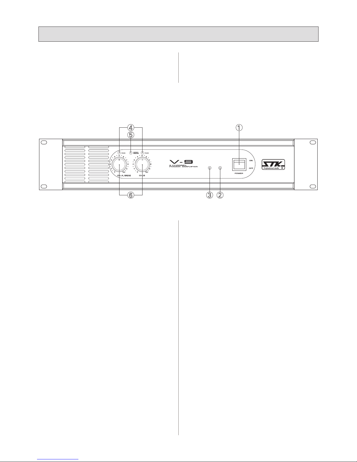
1. Power On/Off Switch
2. Power Indicator LED
3. Protect Indicator LED
If protect conditions should occur, such as a short in a
speaker cable or connector or excessively high operating
temperatures, this LED will light and the amplier will stop
operation until the protect condition is corrected.
4. Peak Indicator LED
Indicates that channel of the amplier is being driven past
normal power limits into distortion.
5. Bridge Mode Indicator LED
Shows when channels 1&2 are in the bridged mono mode.
6. Input Level Attenuator
In the bridge mode, only the channel A attenuator is
functional.
1. 전원 스위치
2. 전원 표시등
3. 보호모드 동작 표시등
스피커 케이블이나 연결선이 쇼트 되어 회로내의 이상이 발생하거
나 기기가 과열되는 등의 보호회로가 동작되어야 할 상황이 발생할
경우 점등됩니다.
4. 피크 레벨 표시등
앰프의 채널이 일반 출력의 한계치를 넘어서서 일그러짐이 발생하
려 하면 점등됩니다.
5. 브릿지 모드 표시등
채널 1와 2가 브릿지 모노 모드 인지를 알려줍니다.
6. 음량 레벨 조절기
브릿지 모드로 사용할 경우에는 채널 A의 음량 조절기만이 활성화
됩니다
PROTECT
POWER
63 2
4 1
5

Ⅰ Introduction
l
제품 소개
6
7. XLR Inputs
Low impedance, balanced inputs accept a male XLR
connector.
8. Through Out Jacks
Accept a female connectors for parallel connect to next
ampliers.
9. Mode Switch (Stereo-Bridge)
Stereo mode : Each channel remains independent, and each
channel may be used for a different signal.
Bridge mode : This setting combines both channels into
a single channel with twice the output voltage .Use only
channel 1’s input and gain control (channel 1 and channel
2’s inputs are internally connected in parallel). Do not use
channel 2’ inputs when operating in Bridge mode.
10. Speakon Output Connectors
Separate NL4 connectors for CH 1 and CH 2 speaker
outputs.
Note: when making Speakon cables, be sure to connect
the loudspeaker wiring as shown on the chassis. Channel
1’s Speakon provides 3 –wire (Ch1 + Positive only of Ch2)
connection : Channel 2’s Speakon provides 2-wire(Ch2 only)
connection.
Table of Contents “(4) Operate your system” provides
Speakon connection reference.
Note ; Speaker connections by speakon jacks and it provides
a safe and reliable connection capable of transferring high
power signals if properly connected.
To avoid ANY possible shock hazard, the power amplier
should be disconnected from the AC power source before
making any connections. When connecting your speakers
using speakon jacks method, be sure to pay close attention to
proper polarity. Although connecting your speaker systems
out of phase using the wrong polarity will not damage your
speakers, it will affect the quality of sound.
When using bare wire connections, be sure that your
connections are "clean." If any strands of wire from one
connector are allowed to touch the adjacent connector,
7. XLR 입력단자
돌출형 XLR 컨넥터를 끼우는 낮은 임피던스, 밸런스드
입력단자입니다.
8. 입력신호 XLR 출력부
함몰형 XLR 컨넥터를 사용하여 다른기기와 입력신호를 병렬
사용하게합니다
9. 모드 스위치 (스테레오 -브릿지 )
Stereo 모드 ; 채널별로 서로 다른 입력신호를 넣으면 모든
입출력은 각 채널별로 독립적으로 작동하게 됩니다.
Bridge 모드 ; 2개 앰프 채널을 하나의 싱글앰프로 콤바인시켜
2배의 출력을 얻게합니다. 반드시 1번 채널 입력과 1 번채널
게인콘트롤 만 사용하세요(자체적으로 1과 2 채널의 입력부가
이미 병렬 상태로 접속되어집니다). 브릿지 모드에서는 절대 채널
2 의 입력은 사용해서는 안됩니다.
10. 스피콘 타입 스피커 연결부
스피커 출력 채널1과 채널2에 대한 NL4 방식 컨넥터(잭)입니다.
참고 : 스피콘 케이블을 연결할때에는 반드시 제품후면부에 표시된
연결 내용을 유의해야합니다. 즉 채널 1의 스피콘 출력 커넥터는
모두 3개의(채널1 +채널2 는 +만 )출력 와이어가 연결되어
있으며, 채널2의 스피콘출력 커넥터는 2개의(오로지 채널
2출력)출력와이어 가 연결되어 있습니다.
목차“(4) 의 시스템 동작하기”의 Speakon 컨넥터 연결에 대한
내용을 꼭 지켜주세요.
참고 : 스피커 연결은 speakon 짹에 의해 이루어지며 안전하고
믿을 수 있게 연결이 잘 되어 있다면 완벽하게 높은 파워의 신호를
전달합니다. 가능한 모든 사고를 예방하기 위해서 연결이 확실히
이뤄지기 전에는 절대 전원을 연결하지 마십시오.
또한, 스피콘 방식으로 스피커를 연결한다면 올바르게 극성을
연결하도록 주의를 기울이십시오.
극성을 잘못 연결했음에도 불구하고 스피커에 손상을
입히지 않는다면 반드시 음질에 문제가 생길 것입니다. 베어
와이어(연심투명선)를 사용하여 연결할 경우 간단하고 깔끔하게
연결이 잘 되었는지 확인해야 합니다.
만약 한 가닥이라도 접속단자에 인접하여 단자를 건드리게 된다면
앰프에 손상을 입힐 것이며 다른 사운드 시스템에도 손상을 입히게
됩니다.
3. Panel Descriptions
l
각 부의 명칭
REAR PANEL SECTION / 후면부
OUTPUT POWER
450Wx2 / 4 ohm
900W / 8 ohm (Bridge)
10A 250V 20A 250V
1=GND
3=COLD(-)
2=HOT(+)
1=GND
3=COLD(-)
2=HOT(+)
THROUGH
900W / 8 ohm(Bridge)
CH 2 CH 1
900W / 8 ohm
450W / 4 ohm
300W / 8 ohm
450W / 4 ohm
300W / 8 ohm
CH 1
CH 1
CH 2
CH 2
CH 1
CH 2
CH 1
CH 2
10 7
8
9
11 12

Ⅰ Introduction
l
제품 소개
damage to your amplier and sound system could occur.
11. AC Mains Connection
Connect AC power to the IEC socket.
Note : Turn off the AC power switch before connecting AC
power. Connect the AC mains plug to a suitable AC mains
outlet.
12. Cooling Air Port.
Air ows from the rack, into the front of the amplier,
and out of the back. This keeps the rack cool. The fan
automatically runs faster when the amp is working hard. Do
not obstruct air ow to this opening.
11. AC 메인 전원 접속부
AC 메인 전원을 연결하는 IEC표준형 전원입력소켓입니다.
참고 :전원 스위치가 꺼진상태에서 전원을 연결해주세요, 또한
전원플러그를 접속하는 메인전원 콘센트규격은 반드시 제품의
소비전류에 적당한 것이어야 합니다.
12. 통풍구
앰프의 출력과 내부온도가 올라가면 팬은 자동으로 고속 회전하여
앰프내부를 냉각시켜줍니다. 또한 랙 시스템으로부터 앰프
전면에서 후면으로 에어를 통과시키도록 되어 있어서 랙 내부의
온도를 억제시키는 역할도 합니다. 절대 통풍구를 막지 마십시오.
7
3. Panel Descriptions
l
각 부의 명칭

4. Operate Your System
l
시스템 동작하기
A. 제품 설치전 주의사항
STK V-6/V-9 파워 앰프는 외부 연결 장치의 손상이나 오 류에도
안전하도록 설계되어 있습니다. 그렇지만, 다음의 주의사 항들은
꼭 지켜주세요.
1. 안전을 위한 주의사항
본 사용 설명서의 4페이지에 나와 있는 안전을 위한 주의사항을 반
드시 읽고 숙지하시기 바랍니다.
본 제품이 물이나 다른 액체에 젖지 않도록 주의해 주십시오. 제품
이 물에 젖을 경우 반드시 전원 플러그를 전원으로부터 분리해 주
십시오. 그렇지 않으면 감전사고로 인해 상해를 입거나 사망할 수
있습니다.
2. 접지
만약 파워 앰프가 접지용 전원선과 플러그로 이루어진 세 개의 컨
덕터로 된 전원선을 가지고 있다면 반드시 그것과 적합한 전원 아
울렛에 연결하여야 합니다.
그라운드 리프트 어댑터를 사용하거나 플러그의 접지부를 없애고
사용해서는 안 됩니다. 부적절하게 접지 플러그를 사용하면 기기
에 손상을 가할 수 있으며 다른 기기에도 위험한 문제를 초래할 수
있습니다.
3. 라인 전압 주의
STK V-6/V-9은 생산단계에서부터 정격라인전압(120V or 220-
240V)에 적합하도록 되어 있으며 전원 코드와 퓨즈가 함께 제 공
됩니다. 퓨즈의 교환이 필요할 경우 반드시 제품과 사용 설명서 제
품규격페이지 에 기재되어 있는 동일한 타입의 퓨즈를 사용하시기
바랍니다. 라인 전압이 ±5%를 넘지 않는 교류 전압을 사용해 주십
시오. 이 를 어길 경우에는 제품 보증 대상에서 제외됩니다.
4. 연결 전 주의사항
제품의 연결 전에 전원을 끄고 모든 컨트롤 스위치를 최소로 하여
주십시오. 이는 스피커 시스템에 손상을 입힐 수 있는 연결 시 순
간적으로 예상치 못한 큰 소리를 내는 경우를 방지 할 수 있습니다
B. 제품의 설치
본 기기는 19인치 표준 랙에 장착되도록 설계되어있습니다. 또한
안전을 위해 미끄럼 방지용 러버 풋이 함께 제공됩니다. 1대 이상
의 앰프를 함께 설치한다거나 다른 장비와 함께 설치하실 때에는
방열을 위하여 제품의 전면과 후면에는 공기의 흡입과 배출이 쉽
도록 막히지 않게 설치해 주십시오.
A. OPERATE PRECAUTIONS
Your STK V-6 and V-9 power amplier are well protected
from any external faults. However, we recommend following
these common-sense precautions:
1. Safety Instructions
Read and follow all of the safety warnings on page 4 of this
manual and on the separate safety precautions page enclosed
with the unit. Do not expose the V-6 and V-9 to water or
other liquids.
Always unplug the unit if water is present. Failure to do so
can result in injury or death from electric shock.
2. Grounding
If your power amplier is supplied with a three conductor,
grounded power cord and plug, connect the unit only to a
properly grounded mains outlet. Do not use a ground lift
adapter or otherwise attempt to defeat the ground on the
plug. Failure to properly ground the unit can result in damage
to the amplier or other equipment connected to it and
represents a dangerous safety hazard.
3. Line Voltage
Your STK V-6 and V-9 is pre-wired at the factory for the
correct line voltage (120V or 220-240V) and is furnished
with the appropriate power cord and fuse.
If fuse replacement is necessary, always use a fuse with the
exact type and rating as specied on the specications page
of this manual or as indicated on the unit itself.
Operate from AC mains not more than 5% above or below
the specied line voltage. Failure to comply may invalidate
your warranty.
4. Pre-Connection Caution
Always switch off the power and set all the level controls to
minimum before making any connections.
This will eliminate any chance of unexpected, loud audio
transients that could damage your speaker systems
B. MOUNTING
The V-6 and V-9 are designed for standard 19″rack mounting.
In addition, the amplier are provided with sturdy no-skid
rubber feet for secure table top or stacked operation. When
rack mounting one or more ampliers or when mounting in
combination with other equipment, be sure to allow adequate
front and rear ventilation to avoid possible heat related
damage to your V-6 and V-9 or other rack mounted items.
8

4. Operate Your System
l
시스템 동작하기
C. 커넥터와 케이블 연결
1. 스피콘 연결
Speakon 컨넥터는 저전압 고전류를 위해 설계 되어있습니다.
각각의 컨넥터는 1+, 1-, 2+ 그리고 2- 로 표시된 2쌍의 컨덕터로
이루어져 있습니다.
첫번째 컨덕터에서 1+ 와 1-이 보내지고, 2+ 와 2-를 보내는 두
번 째 컨덕터는 컨넥터에 두 번째 출력 신호가 있는 경우에만 쓰입
니 다. NL4FC 컨넥터를 끼울 때에는, 컨넥터가 확실히 잘 끼워졌
는 지를 확인하시고, 시계방향으로 45°돌려 컨넥터를 잘 고정시켜
주십시오.
9
C. CONNECTION CABLES & CONNEC- TORS
1. Speakon Connections
Speakon connectors are purpose-built for low voltage, high
current applications.
Each connector incorporates two pair of conductors, labeled
1+, 1-, 2+ and 2-.
By convention, single signals are sent on 1+ and 1-.
The second pair, 2+ and 2-, are used only if there is a second
unique signal present at the connector. When attaching
NL4FC mating connectors, be sure to insert the connector to
its full depth, then turn the connector 45°clockwise to lock it
in place.
Output Function l 출력기능 Connector l 컨넥터 Pins l 핀
Speaker # 1 CH 1 1+(Speaker +), 1-(Speaker -)
Speaker # 2 CH 2 1+(Speaker +), 1-(Speaker -)
Bridged Mono CH 1 1+(Speaker +), 2+(Speaker -)
Amplifier connection To loudspeaker
Two-wire, single-channel connection
Four-wire, two-channel connection
Bridge mode connection
NOTE! Ensure proper polarity when
connecting bridge mode output!
4. Operate Your System
l
시스템 동작하기
2. INPUT/INPUT THROUGH CONNECTIONS
The STK, V-6/V-9 power ampliers are designed to be as
versatile as possible. The following descriptions of the input
and output connections are designed to help you maximize
the unit's potential.
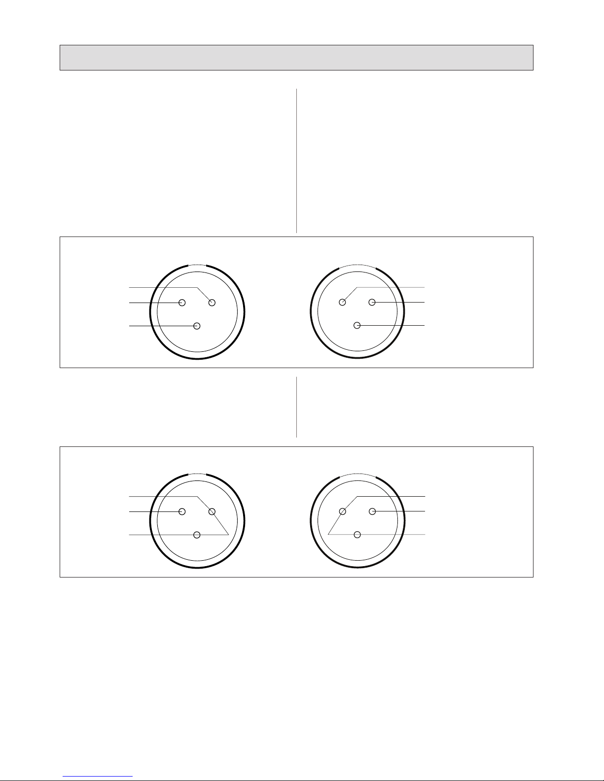
1). BALANCED XLR Input Jacks / Through Jacks
Electronically balanced input accepts a standard XLR male
and female connector.
Pin1=ground, Pin2=hot or positive (+).
Pin3=cold or negative (-).
2). UNBALANCED XLR Input Jacks / Through Jacks
Electronically unbalanced input accepts a standard XLR male
and female connector.
Pin1=ground, Pin2=hot or positive (+).
Pin3=ground (-).
2. 입력신호 입출력 XLR 단자 연결
STK V-6/V-9 파워 앰프는 가능한 다양한 응용이 가능하도 록 설
계되었습니다. 다음의 입출력 연결에 대한 설명은 기기의 활 용을
극대화 할 수 있도록 도와줄 것입니다.
1). 밸런스드 XLR 입력 잭 / 입력신호 XLR 출력잭
전기적으로 밸런스드 입력신호 용인 표준규격의 XRL
돌출형과 함몰형 컨넥터를 연결합니다.
2). 언밸런스드 XLR 입력 잭 / 입력신호 XLR 출력잭
전기적으로 언밸런스드 입력신호 용인 표준규격의 XRL
돌출형과 함몰형 컨넥터를 연결합니다.
Female Type Input Jacks l 함몰형 입력잭 Male Type Through Jacks l 돌출형 입력신호 출력잭
1. GROUND
(shield)
2. HOT +
3. COLD -
12
3
1. GROUND
(shield)
2. HOT +
3. COLD -
1 2
3
Female Type Input Jacks l 함몰형 입력잭 Male Type Through Jacks l 돌출형 입력신호 출력잭
1. GROUND
(shield)
2. HOT +
3. GROUND
(-)
12
3
1. GROUND
(shield)
2. HOT +
3. GROUND
(-)
1 2
3
10
11
D. V-9/V-6 스테레오 동작
스테레오 모드에서는 4Ω 의 기본적인 동작 구성을 권장 합니다.
각각의 채널은 입력 단자에서 받은 신호에 따라 각 스피커 출력단자
에 분리된 개별 신호를 내보냅니다.
V-9/V-6는 스테레오 동작을 위해 두 개의 채널을 가지고 있습니
다. 다음 사용 방법을 잘 읽어 주십시오.
1. 모노/브릿지 스위치
후면부의 모노/브릿지 스위치를 스테레오 모드에 위치시킵니다.
전원이 켜지면 모노/브릿지 표시등이 꺼져있을 것입니다.
만약 표시등이 켜져 있다면 스위치가 잘못 위치한 것입니다. 스위치
를 올바르게 위치시켜 주십시오.
2. 입력단자연결
전원을 끈 상태에서 입력 선들을 채널 A와 B에 연결합니다.
3. 스피커 연결
그림 3을 참고해서 스피커 시스템을 연결해 주십시오. 각 채널당 스
피커의 합성 임피던스는 최소한 4Ω이 되어야 합니다.
각 채널 당 로드 임피던스가 4Ω 이하일 때에는 본 기기가 동작하지
않습니다.
4. 음량 조절
모든 볼륨 조절기를“0”에 놓고 전원을 켜 주십시오. 그리고 적정
수준의 신호를 입력하십시오. 다음으로 본 기기의 음량조정 볼륨을
원하는 만큼 알맞게 조정하여 주십시오. 이러한 방식은 우수한 신호
대 잡음비에 의해 앰프의 출력을 기본 노이즈 플로어로부터 보다 멀
리 떨어뜨릴 수 있습니다.
피크 표시등이 켜질 때까지 원하는 만큼 가장 높은 수준까지 볼륨을
조절해 보십시오. 피크 표시등이 켜지지 않게 이러한 방식으로 볼륨
을 조절하면 지속적으로 맑고 풍부한 음질을 유지할 수 있습니다.
피크 표시등이 켜지면 앰프의 출력에 일그러짐이 발생한 것입니다.
꼭 기억하세요.
D. STEREO OPERATION
The basic method of operation is recommended for 4 Ohm
applications. Each channel provides a separate and discrete
signal at the speaker outputs according to the signal received
at the inputs. The V-9 and V-6 has two channels for stereo
operation. Follow these steps to use the amplier in this
manner:
1. Set Mono/Bridge switch
Set the mono/bridge switch on the rear panel to the stereo
position. When the power is on, the mono/bridge LED on
the front panel will not light. If the LED illuminates, you
have the switch in the wrong position.
Change the switch before continuing.
2. Input Connections
With the power off, connect your input source lines to
channels A and B.
3. Connect Speaker Systems
Connect speaker systems to speaker outputs as shown gure
3. The total speaker load for each channel must be at least 4
ohms.
The amplier will not operate at load conditions lower than 4
ohms per channel.
4. Level Controls
With all level controls set to 0, switch the power on. Apply
a nominal signal to the inputs. The level of the input signal
should be about as high as you will ever need it to be. This
way, it will be as far above the amplier's noise oor as
possible, ensuring as excellent signal to noise ratio. Adjust
the input level control for each channel to achieve the desired
maximum listening level or until the peak LED ashes
momentarily during program peaks, whichever is lowest.
Having set the levels in this manner will render a clean signal
at any level as long as the peak LED is not constantly on.
Remember, when the peak LED lights, there is distortion
present in the amplier's output section.
4. Operate Your System
l
시스템 동작하기
OUTPUT POWER
450Wx2 / 4 ohm
900W / 8 ohm (Bridge)
10A 250V 20A 250V
1=GND
3=COLD(-)
2=HOT(+)
1=GND
3=COLD(-)
2=HOT(+)
THROUGH
900W / 8 ohm(Bridge)
CH 2 CH 1
900W / 8 ohm
450W / 4 ohm
300W / 8 ohm
450W / 4 ohm
300W / 8 ohm
CH 1
CH 1
CH 2
CH 2
CH 1
CH 2
CH 1
CH 2
FIGURE 3. Speaker Connection Guide For Stereo Operation.
그림 3. 스테레오 모드 동작을 위한 스피커 시스템 연결 가이드.

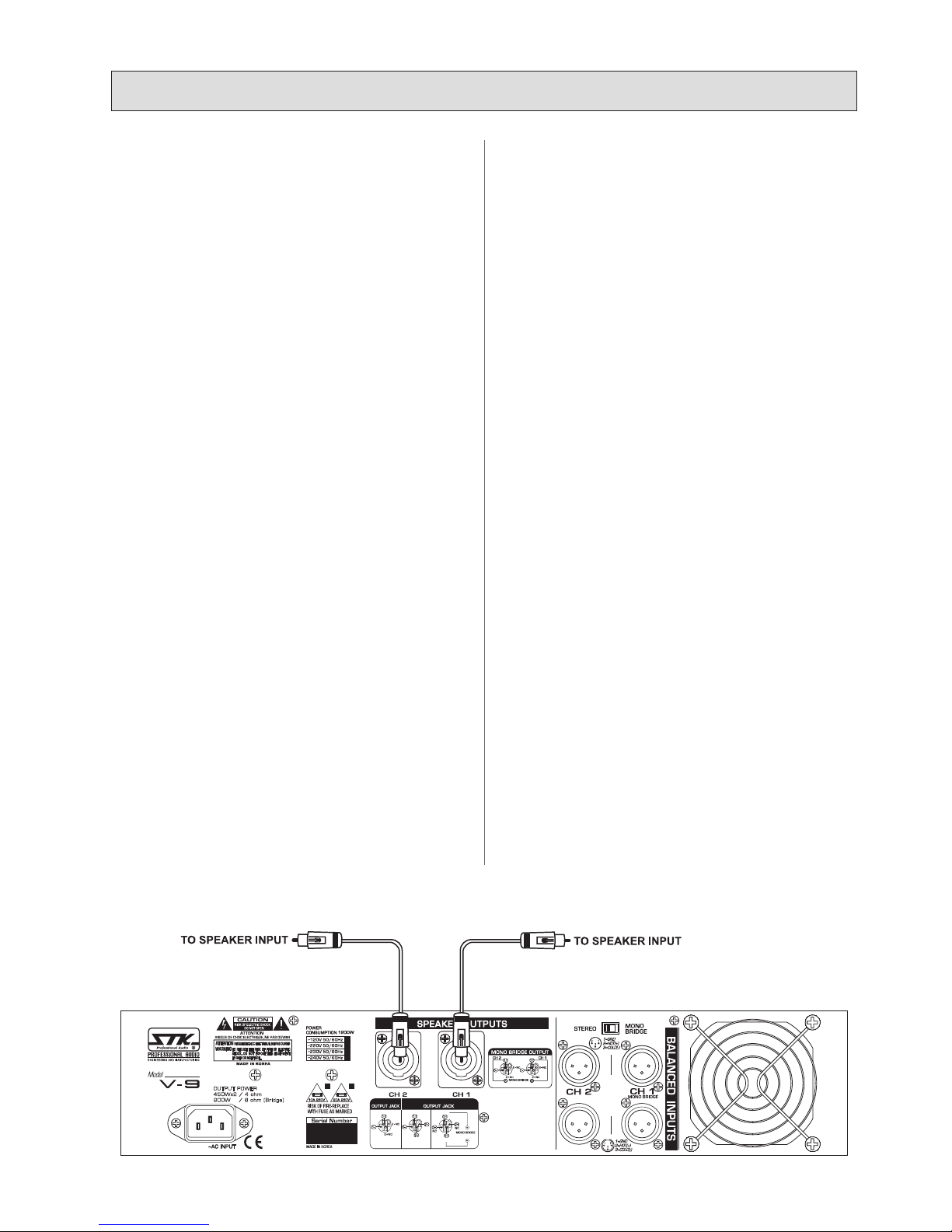
E. 모노/브릿지 모드 동작
브릿지/모노 모드의 최소 스피커 입출력 임피던스는 8Ω 입니다.
V-6가 모노럴 또는 싱글 채널로 변환되면 8Ω의 부하에 600와트
의 출력을 공급합니다.
V-9가 모노럴 또는 싱글 채널로 변환되면 8Ω의 부하에 900와트
의 출력을 공급합니다.
1. 모노/브릿지 모드 스위치
모노/브릿지 모드를 사용하길 원하시면 제품 후면부의 브릿지 모
드 스위치를 모노/브릿지 모드로 위치 시켜 주십 시오.
전원이 켜면 모노/브릿지 모드 표시등이 점등 될 것입니다.
표시등이 점등되지 않는다면 스위치를 다시 확인해 주십시 오.
2. 입력 신호선
전원을 끈 상태에서 입력 신호 선들을 채널 A에만 연결해 주십시
오.
3. 스피커 출력
그림 4와 같이 스피커 시스템을 연결해 주십시오.
스피커의 합성 임피던스는 최소한 8Ω 또는 그 이상이어야 합니다.
만약 브릿지 모드에서 8Ω이하로 본 앰프를 동작 시키려 할 경우
자동으로 보호 모드로 전환되어 작동이 중지 될 것입니다.
4. 볼륨 조절
모든 볼륨 조절기를 “0”에 놓고 전원을 켜 주십시오. 그리고 적정
수준의 신호를 입력하십시오. 다음으로 본 기기의 음량조정 볼륨을
원하는 만큼 알맞게 조정하여 주십시오. 이러한 방식은 우수한 신
호 대 잡음비에 의해 앰프의 출력을 기본 노이즈 플로어로부터 보
다 멀리 떨어 뜨릴 수 있습니다.
피크 표시등이 켜질 때까지 원하는 만큼 가장 높은 수준 까지 볼륨
을 조절해 보십시오. 피크 표시등이 켜지지 않게 이러한 방식으로
볼륨을 조절하면 지속적으로 맑고 풍부한 음질을 유지할 수 있습니
다. 피크 표시등이 켜지면 앰프의 출력에 일그러짐이 발생한 것입
니다. 꼭 기억하세요.
E. MONO/BRIDGE OPERATION
The method of operation bridges inputs and outputs and can
be used with 8 ohm or higher applications only. Bridging the
V-9/V-6 converts the V-9/V-6 to a monophonic or single
channel amplier, providing 900 watts(V-6: 600 watts) into a
single 8 ohm load.
1. Set Mono/Bridge switch
Set the switch on the rear panel for channel you wish to
operate in the bridge mode to the mono/bridge position.
When the power is on, the mono/bridge LED on the front
panel will light. If the LED does not illuminates, you have
the mono/bridge switch in the wrong position. Change the
appropriate switch before continuing.
2. Input Source Lines
With the power off, connect your input source lines to
channels1A only.
3. Speaker Outputs
Connect speaker systems to speaker outputs only as shown
in gure 4. The total speaker load must be at least 8 ohms or
above. If you try to operate at less than 8 Ohms in the
bridge mode, the amplier will go into protect mode and
stop operation until you correct the load condition.
4. Level Controls
With all level controls set to 0, switch the power on. Apply
a nominal signal to the inputs. The level of the input signal
should be about as high as you will ever need it to be. This
way, it will be as far above the amplier's noise oor as
possible, ensuring as excellent performance signal to noise
ratio. Adjust the input level controls for channel A to achieve
the desired maximum listening level or until the peak LEDs
ash momentarily during program peaks, whichever is lowest.
Having set the levels in this manner will render a clean signal
at any level as long as the peak LEDs are not constantly on.
Remember, when the peak LEDs light, there is distortion
present in the amplier's output section.
4. Operate Your System
l
시스템 동작하기
OUTPUT POWER
450Wx2 / 4 ohm
900W / 8 ohm (Bridge)
10A 250V 20A 250V
1=GND
3=COLD(-)
2=HOT(+)
1=GND
3=COLD(-)
2=HOT(+)
THROUGH
900W / 8 ohm(Bridge)
CH 2 CH 1
900W / 8 ohm
450W / 4 ohm
300W / 8 ohm
450W / 4 ohm
300W / 8 ohm
CH 1
CH 1
CH 2
CH 2
CH 1
CH 2
CH 1
CH 2
Use CH.A Input Only
A 채널만 입력하세요
FIGURE 4. Speaker Connection Guide For Mono Bridge Operation.
그림 4. 브릿지/모노 모드 동작을 위한 스피커 시스템 연결 가이드.
12

4. Operate Your System
l
시스템 동작하기
13
F. 전면부의 표시등
전면부의 여러 표시등들은 V-6 / V-9 앰프의 상황 별 여러 동작
상태를 알려줍니다.
여러 표시등의 의미를 정확히 알면 앰프를 사용하기 훨씬 편리합니
다.
1. 피크 표시등
피크 표시등은 각 채널에 입력되는 신호의 세기가 너무 강해 출력
에 일그러짐이 일어나는 것을 알려줍니다.
프로그램이 최고조인 동안 피크 표시등이 깜박이며 동작 동안 지속
적으로 점등되지는 않습니다.
지속적으로 표시등이 켜져 있다면 음질이 일그러지는 것을 알 수
있을 것입니다. 이러한 일그러짐은 스피커 시스템에 큰 손상을 가
져옵니다.
이런 경우에는 일그러짐이 일어나는 채널의 음량 조절기를 줄여주
시기 바랍니다.
앰프를 모노/브릿지 모드로 사용할 경우에는 브릿지 모드 의 피크
표시등 모두 동시에 동작하게 됩니다.
2. 모노/브릿지 표시등
모노/브릿지 표시등은 앰프 후면부의 모노/브릿지 스위치 를 모
노/브릿지 모드에 위치시켰을 때 켜집니다.
앰프의 전원을 켜기 전에 항상 스위치가 올바른 위치에 있는지 확
인하시고 모든 스피커 연결을 정확하게 구성해 주십시오.
3. 보호모드 표시등
보호모드 표시등은 앰프 외부의 연결에 문제가 있거나 부하 또는
온도, 그리고 내부의 기능에 문제가 생겼을 경우에 점등됩니다. 문
제 상황 발생시 앰프는 자동으로 보호 모드 스위치를 켭니다.
보호모드로 전환되면 앰프는 모든 동작을 멈추고 보호모드 표시등
을 점등시킵니다. 보호모드 표시등이 켜지면 앰프의 전원을 꺼주십
시오. 문제를 일으킨 요소를 올바르게 바로 잡았다면 앰프의 전원
을 다시 켜주십시오.
만약 그럼에도 불구하고 보호모드 표시등이 켜진 채로 있다면 앰프
의 사용을 중단하시고 STK 고객 서비스 팀이나 영업사원을 통해
앰프를 수리 하십시오.
4. 전원 표시등
전원표시등은 앰프에 AC 주 전원이 연결되어 전원이 들어 올 경우
켜집니다.
F. FRONT PANEL INDICATORS
The front panel of the V-9 and V-6 has several indicators to
alert you to the status of various operating conditions.
Knowing what these indicator LEDs are telling you will help
you to use your STK amplier.
1. Peak LED
A peak LED for each channel indicates that your signal level
is so strong that there is distortion at the output
of that channel. While it is normal for the peak LED to
ash during program peaks, the LED should not remain
constantly lit during operation. If it does, most likely you
will hear the results in the form of distorted sound that can
be damaging to your speaker systems. In this case, reduce
the signal level by lowering the input level control for the
channel that is clipping or reduce the level at the source.
Note that when using the amplier in the mono/bridge
mode, both peak LEDs of the bridged channels will operate
simultaneously.
2. Mono/Bridge LED
The mono/bridge LED will light when you have set the
rear panel switch to the mono/bridge position for bridged
operation. Always make sure that this switch is in the correct
position and that all speaker connections
have been made correctly for the mode of operation you wish
to use before powering up the amplier.
3. Protect LED
The protect LED indicates that there is a problem either in
the amplier's external connections, load or
temperature conditions or its internal functions. If one of
these situations occurs, the amplier senses the
problem and automatically switches into its "protect mode."
The protect LED will light to warn you of the
trouble and the amplier will stop working. If this happens,
switch off the amplier.
If you feel that you have been able to correct the fault
condition that caused the amplier to go into the protect
mode, restart the amplier.
If the protect LED remains lit when attempting to resume
amplier operation, do not use the amplier.
Refer the amplier to an authorized STK service facility or
contact your dealer for help.
4. Power Indicator LED
The power indicator LED indicates that the power switch is
in the on position and that AC mains power is applied.
14
Ⅰ Introduction
l
제품 소개
OUTPUT POWER
450Wx2 / 4 ohm
900W / 8 ohm (Bridge)
10A 250V 20A 250V
1=GND
3=COLD(-)
2=HOT(+)
1=GND
3=COLD(-)
2=HOT(+)
THROUGH
900W / 8 ohm(Bridge)
CH 2 CH 1
900W / 8 ohm
450W / 4 ohm
300W / 8 ohm
450W / 4 ohm
300W / 8 ohm
CH 1
CH 1
CH 2
CH 2
CH 1
CH 2
CH 1
CH 2
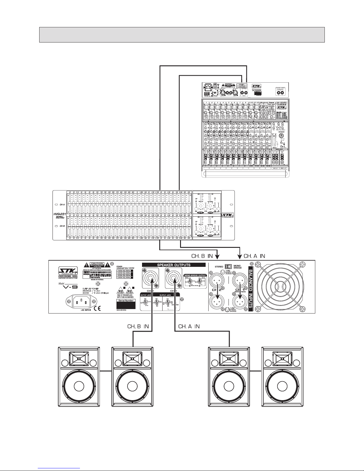
HVQ-231
Graphic Equalizer
V-9
Power Amplifier
VX-1604FX
Console Mixer
FULL RANGE 15” ENCLOSURES
5. System Hookup Diagram
l
시스템 연결 구성도
STEREO PA SYSTEM l 스테레오 라이브/PA 시스템
15
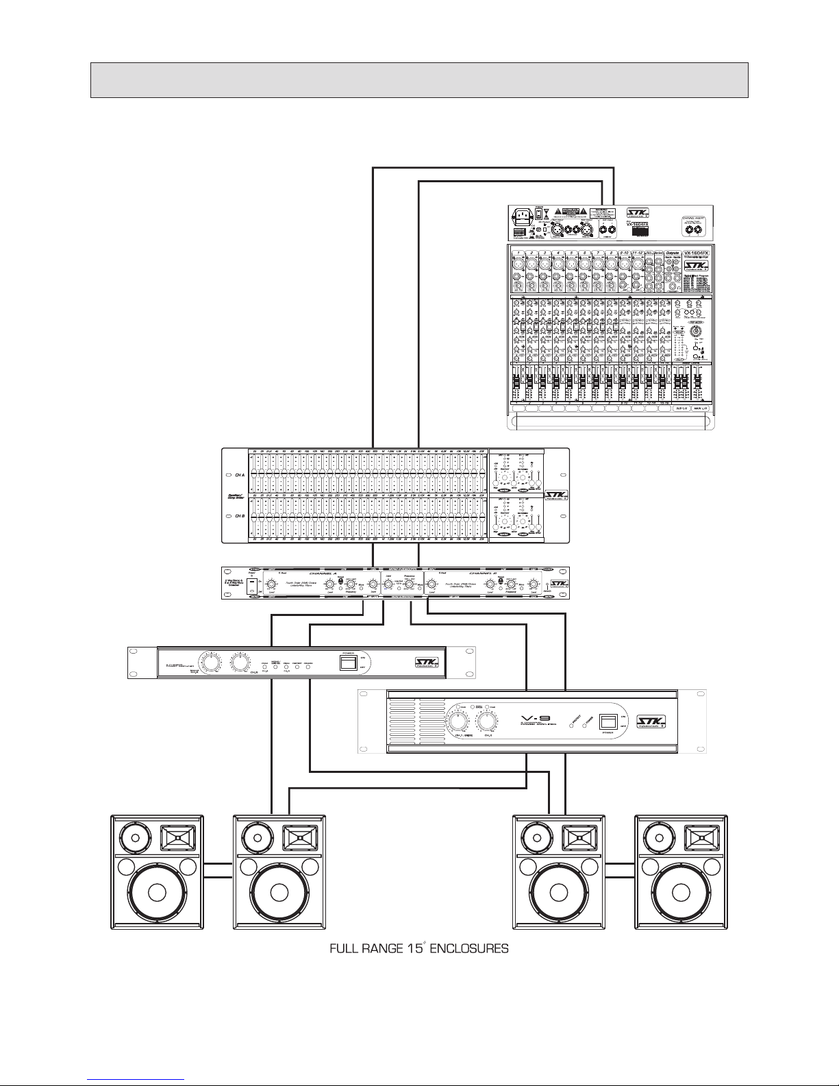
HVQ-231
Graphic
Equalizer
VC-23
Electronic
Crossover
V-9, Power Amplifier
V-2
Power Amplifier
L-Hi
L-IN
R-IN
R-OUT
L-OUT
R-Hi
L-Low R-Low
VX-1604FX
Console Mixer
5. System Hookup Diagram
l
시스템 연결 구성도
STEREO BI AMP SYSTEM l 스테레오 바이 앰프 시스템

16
6. Block Diagram
l
회로의 구성도

17
7. Specications
l
제품 규격
V-9
Output Power Per Channel / 최대 출력
at 1㎑ / THD ≤1.0% EIA
4 Ω
8 Ω
440W
300W
Output Power Both Channel Drive / 정격 출력
at 20㎐~20㎑ / THD ≤0.1%
4 Ω
8 Ω
8 Ω Bridged
2×430W
2×290W
1×860W
Total Harmonic Distortion / 왜율
f=1 ㎑, at rated power <0.05%
IMD-SMPTE / 혼합변조왜율
4Ω, Stereo, 1/2 power
f=60㎐+7㎑, 4:1
<0.1%
Frequency Response / 주파수 응답
-1㏈, 1Watt output 20㎐ - 30㎑
Power Bandwidth -1.5㏈,Stereo / 전력 대역폭 20㎐ - 20㎑
Signal To Noise Ratio / 신호대 잡음비
A-weighted. RMS ≥105 ㏈
Residual Noise / 잔류 잡음
LPF level minimum ≥-76 ㏈
Damping Factor 8Ω, 50 ㎐ / 댐핑 팩터 ≥350
Slew Rate 8Ω, 1㎑, Rated Output / 슬루율 49 V/μsec
Channel Separation 8Ω, 1㎑, Rated Output
/ 채널 분리도 ≥70 ㏈
Input Sensitivity (VR Max.) / 입력 감도 +4㏈ (0.78V)
Input Impedance / 입력 임피던스 ≥10 k ohm
Indicators *1 / 표시등 1, 2, 3, 4
Cooling / 냉각방식 Variable Fan
Protection Circuit *2 / 보호회로 *2 1, 2, 3, 4, 5, 6
Front Panel Controls / 전면부 조절 Level, Ach, Bch
Rear Panel Controls / 후면부 조절 Stereo/Mono Mode Switch
DC Offset Voltage / 출력 중점 직류전압 ≥DC 10㎷
Dimension (W×D×H) mm / 외형 칫수
inch
483×407×89mm
19.0×16.0×3.5
Weight Net / 제품 무게
lbs(㎏) Shipping / 포장박스 포함
35.75 (16.22)
41.31 (18.74)
Power Consumption / 소비전력 1200 Watts
AC Fuse / 입력 퓨즈 120V: 20A, 220V/240V: 10A
Connector / 사용커넥터
All input balanced type.
/ 모든 입력은 밸런스드 타입입니다.
XLR input,
1/4″input,
Binding Post
Speakon
*1. Indicator l 표시등 : 1) Power On, 2)Protect Mode, 3)Mono Bridge Mode, 4)Peak
*2. Protection Circuit l 보호 회로 : 1) Short Circuit, 2)Current Limit, 3)Thermal Cutoff, 4)DC Fault,
5) Power Up/Down Transients, 6)AC Fuse
*Specifications are subject to change without notice.
NOTES :

18
7. Specications
l
제품 규격
V-6
Output Power Per Channel / 최대 출력
at 1㎑ / THD ≤1.0% EIA
4 Ω
8 Ω
8 Ω Bridged
2×300W
2×200W
1x600W
Output Power Both Channel Drive / 정격 출력
at 20㎐~20㎑ / THD ≤0.1%
4 Ω
8 Ω
8 Ω Bridged
2×290W
2×10⁵W
1×560W
Total Harmonic Distortion / 왜율
f=1 ㎑, at rated power <0.05%
IMD-SMPTE / 혼합변조왜율
4Ω, Stereo, 1/2 power
f=60㎐+7㎑, 4:1
<0.1%
Frequency Response / 주파수 응답
-1㏈, 1Watt output 20㎐ - 30㎑
Power Bandwidth -1.5㏈,Stereo / 전력 대역폭 20㎐ - 20㎑
Signal To Noise Ratio / 신호대 잡음비
A-weighted. RMS ≥100 ㏈
Residual Noise / 잔류 잡음
LPF level minimum ≥-70 ㏈
Damping Factor 8Ω, 50 ㎐ / 댐핑 팩터 ≥300
Slew Rate 8Ω, 1㎑, Rated Output / 슬루율 32 V/μsec
Channel Separation 8Ω, 1㎑, Rated Output
/ 채널 분리도 ≥70 ㏈
Input Sensitivity (VR Max.) / 입력 감도 +4㏈m (1.23V)
Input Impedance / 입력 임피던스 ≥15 ㏀
Indicators *1 / 표시등 1, 2, 3, 4
Cooling / 냉각방식 Variable Fan
Protection Circuit *2 / 보호회로 *2 1, 2, 3, 4, 5, 6
Front Panel Controls / 전면부 조절 Level, Ach, Bch
Rear Panel Controls / 후면부 조절 Stereo/Mono Mode Switch
DC Offset Voltage / 출력 중점 직류전압 ≥DC 10㎷
Dimension (W×D×H) mm / 외형 칫수
inch
483×407×89mm
19.0×16.0×3.5
Weight Net / 제품 무게
lbs(㎏) Shipping / 포장박스 포함
31.65 (14.36)
36.37 (16.50)
Power Consumption / 소비전력 980 Watts
AC Fuse / 입력 퓨즈 120V: 10A, 220V/240V: 6.3A
Connector / 사용커넥터
All input balanced type.
/ 모든 입력은 밸런스드 타입입니다.
XLR input,
1/4″input,
Binding Post
Speakon(option)
*1. Indicator l 표시등 : 1) Power On, 2)Protect Mode, 3)Mono Bridge Mode, 4)Peak
*2. Protection Circuit l 보호 회로 : 1) Short Circuit, 2)Current Limit, 3)Thermal Cutoff, 4)DC Fault,
5) Power Up/Down Transients, 6)AC Fuse
*본 자료의 내용은 제품의 성능과 품질 개선을 위하여 예고 없이 변경될 수 있습니다.
NOTES :

19
UNPACKING
As a part of our system of quality control, every STK
product is carefully inspected before leaving the factory
to insure awless appearance.
After unpacking, please inspect for any physical
damage. Save the shipping carton and all packing
materials, as they were carefully designed to reduce the
possibility of transportation damage should the unit
again require packing and shipping.
In the event that damage has occurred, immediately
notify your dealer so that a written claim to cover the
damage can be initiated with the carrier. The right to
any claim against a public carrier can be forfeited if
the carrier is not promptly notied and if the shipping
carton and packing materials are not available for
inspection by the carrier. Save all packing materials until
the claim has been settled.
STK Customer Service Department
3F, 15, Majang-ro 543beon-gil, Gyeyang-gu, Incheon,
Republic of Korea (Zip 21104)
TEL : +82-(0)32-525-1788~1790
FAX : +82-(0)32-525-1784
www.stkpro.com
STK LIMITED 1 YEAR WARRANTY
STK electronics are warranted to be free from defects
in materials and workmanship under normal use for a
period of 1 year from date of original purchase.
During that period, STK will at its option, repair
or replace materials at no charge if product has been
delivered to STK by a STK dealer or STK Service Center
together with the original sales receipt or other proof of
purchase.
Warranty excludes fuses, exterior nish, normal wear,
failure due to abuse, or operation outside of specified
ratings. Warranty applies to original purchaser only.
This warranty gives you specic legal rights which vary
from state to state.
For more information about warranty repair,
please contact : Customer Service Dept., The STK
Professional Audio.
FOR YOUR RECORDS
All of us at STK thank you for your expression
of confidence in STK products. The unit you have
purchased is protected by a limited 1 year warranty. To
establish the warranty, be sure to fill out and mail the
warranty card attached to your product.
For you own protection, ll out the information below for you own records.
Other Information :
8. Warranty Information
Model Number :
Dealer :
Phone :
Serial Number :
Date Of Purchase :
Salesman :

20
8. 제품 보증에 대해서
제품 취급에 대해서
본 제품은 우수한 제품 설계과정을 마치고 엄밀한 품질
관리 및 검사과정을 거쳐서 생산된 제품입니다.
제품을 포장에서 꺼낸 후에는, 물리적 충격을 피해주십
시오. 포장상자와 모든 포장 재료들은 제품의 포장과 이
동 중에 발생할 수 있는 충격을 완화할 수 있도록 설계되
어 있습니다.
서비스 등 다시 제품을 포장하고 이동해야 할 수 있으
므로 포장상자와 재료들을 보관해 주십시오. 만약 제품에
충격이 가해졌을 시에는 즉시 판매원에게 알려 빠른 조치
가 가능하도록 해주십시오.
운송업자와의 상품 인수 과정에서 손상된 포장용 상자
와 재료들은 운송업자에게 즉시 알리지 않으면 차후에 운
송업자에게 불만을 제기할 수 없습니다. 모든 포장용 상
자와 포장 용품을 잘 보관해 두시길 바랍니다.
제품 보증기간은 1년입니다.
STK는 제품을 구입한 날짜로부터 1년 동안 무상으로
AS를 해드립니다. 제품 보증 기간 동안 STK 정식 판매원
이나 STK서비스 센터를 통해 영수증과 함께 본사로 배달
된 제품의 부품의 교환이나 수리는 모두 무료입니다.
퓨즈, 외부흠집 등의 제품의 하자 또는 규격과 다른 내
용 역시 보증내용에 포함됩니다. 보증은 실 구매자에 한
합니다. 이 보증은 국가에 따라 달라질 수 있습니다.
더 자세한 정보를 원하신다면 STK Professional
Audio 고객 서비스 팀에 문의해 주십시오.
올바른 A/S를 받을 수 있도록 제품을 구입하신 후 아래 사항을 기록하여 보관하여 주시기 바랍니다.
기타 기록사항 :
모델 넘버 :
구입처 :
영업사원 :
시리얼 넘버 :
제품 구매일 :
전화번호 :
FOR YOUR RECORDS
저희 제품을 구매해 주셔서 감사합니다. 구매하신 제품
은 1년간의 무상보증기간을 갖습니다. 보증카드를 작성
하셔서 제품과 함께 보내주시면 확실한 서비스를 받으실
수 있습니다.
STK 고객 서비스 팀
인천광역시 계양구 마장로 543번길 15, 3층(효성동)
우편번호 21104
TEL : 032-525-1788~1790
FAX : 032-525-1784
E-mail : stkcom@stkpro.com
www.stkpro.com
This manual suits for next models
1
Table of contents
Other STK Professional Audio Amplifier manuals

STK Professional Audio
STK Professional Audio V-16 Plus 4 User manual

STK Professional Audio
STK Professional Audio VS-34 Power Plus User manual

STK Professional Audio
STK Professional Audio V-3.5M User manual

STK Professional Audio
STK Professional Audio V-6 User manual

STK Professional Audio
STK Professional Audio V-9T User manual

STK Professional Audio
STK Professional Audio VS-25 User manual

STK Professional Audio
STK Professional Audio VS-2004 User manual

STK Professional Audio
STK Professional Audio VP-240D User manual

STK Professional Audio
STK Professional Audio V-2 User manual

STK Professional Audio
STK Professional Audio VS-15 User manual


