STK Professional Audio VC-23 User manual

VC-23 / VC-34
액티브 크로스오버
사용설명서
Active Crossover
OWNER'S MANUAL
VC - 34
3 Way Stereo &
4 or 5 Way Mono
Crossover
VC
- 23
OUTPUT PIN
1=GND
2=HOT(+)
3=COLD(-)
3
2
Level
LOW OUTPUT
LOW OUTPUT
Level Level Level
MID OUTPUT
Level
LOW OUTPUT
2
STK VC-23 / VC-34
액티브 크로스오버
Active Crossover
Table of Contents
l
목 차
1. Introduction l 제품 소개........................................................................................................................................
3
2. Important Safety Instructions l 안전을 위한 주의 사항.....................................................................
4-5
3. Panel Description l 각 부의 명칭 ....................................................................................................................
6-12
4. Connecting Your System l 올바른 설치 방법 .........................................................................................
13-14
5. Operating Your System l 올바른 동작 방법 .............................................................................................
15-29
6. Care and Maintenance l 주의 및 관리 방법...............................................................................................
30
7. Professional Operating Tips l 전문적인 동작 방법 .............................................................................
31-33
8. System Hookup Diagram l 시스템 연결 구성도.....................................................................................
34
9. Block Diagram l 회로의 구성도.........................................................................................................................
35-38
10.
Specications l 제품 규격...................................................................................................................................
39-40
11.
Warranty Information l 제품 보증에 대해서 ..............................................................................................
41-42

3
1. Introduction
l
제품 소개
STK-프로페셔널 오디오의 액티브 스테레오 크로스오
버는 프로페셔널한 성능과 뛰어난 기능과 품질을 컴팩트
하고 경제적인 포맷에 담아낸 제품입니다. VC-23은 스
테레오 2-웨이 크로스오버 이지만 모노 서브우퍼를 추가
할 수 있어 실질적으로는 3-웨이 크로스오버로 볼 수 있
습니다.
또한, 모노 모드로 사용할 때에는 3-웨이 또는 4-웨이
로도 사용 가능합니다.
마찬가지로, VC-34는 스테레오 3-웨이 크로스오버
이지만, 서브우퍼를 추가하게되면 실질적으로는 4-웨이
크로스오버로 볼 수 있으며, 모노 모드로 사용하게 되면,
4-웨이, 5-웨이로도 사용가능합니다.
두 모델 모두 Linkwitz-Riley 필터, 포스 오더를 사용
하였으며, 다른 기기들과 잘 어울리는 특징을 보유하고
있습니다.
이는 저주파, 중주파, 고주파에서의 24dB/옥타브
슬로프를 통해 잘 알 수 있습니다. The 서브우퍼 출력은
12dB/옥타브 슬로프를 가지는 세컨드 오더를 사용하였
습니다. 플랫 리스폰스는 선택한 밴드 패스 영역에 미치
고 있습니다. 입력 레벨 조절기와 클립 표시등 등은 제품
을 타 제품들과 함RP 사용하기에 편리하도록 해줍니다.
수년간의 연구와 신뢰로 완성된 제품으로 사용자에게 보
다 뛰어난 경험을 선사해 줄 것입니다.
The STK-Professional Audio VC-23 and VC-34 active
stereo crossovers offer feature-packed, professional
performance in a compact and economical format. The
VC-23 is a stereo two-way crossover with an additional
mono subwoofer output actually making it a three-way
crossover.
In addition, it can be used in a mono three or four-way
conguration.
The VC-34 is a stereo three-way crossover with an
additional mono subwoofer output making it a four-
way crossover. Similar to the VC-23 the VC-34 can be
used as a mono four or five way crossover. Both of
these units feature matched, fourth order, Linkwitz-Riley
lters.
This results in 24dB/octave slopes for low, mid and
high frequency bands. The subwoofer output uses
second order, 12dB/octave slopes. A flat response is
achieved throughout the selected band pass range. Input
level controls with clip indicators make the STK VC-
23 and VC-34 electronically compatible with all other
professional audio equipment and have been designed
for many years of dependable service.

4
1. 사용 설명서를 꼭 읽어주세요
제품을 사용하기 전에 본 설명서의 안전과 작동에 관한 모든 기능
설명들을 반드시 읽어 보십시오.
2. 사용 설명서를 잘 보관하세요
안전과 작동에 관한 설명은 나중에 참고하게 될 경우가 있으므로
잘 보관해서 유용하게 사용하십시오.
3. 주의 및 경고사항
사용 설명서에 나타나 있는 모든 주의사항들은 반드시 지켜야 합니
다.
4. 사용법을 지켜주세요
본 설명서의 사용법에 관한 모든 내용들은 반드시 지켜야 합니다.
5. 수분과 습기주의
제품은 물기 또는 습기가 많은 곳에 설치하면 감전의 원인이 됩니
다. (욕조, 세면기, 부엌, 세탁기, 젖은 바닥, 수영장의 풀 근처, 습
지 등)
6. 열주의
제품은 전열기구 혹은 열을 발생하는 그 밖의 기구들로부터 떨어진
곳에 설치되어야 합니다. 설치 전 반드시 주변을 확인하시어 건조
한 장소에 제품을 설치해 주십시오.
7. 전원주의
이 제품은 반드시 사용 설명서에 정해진 타입의 전원 또는 본체에
표시된 전원에 연결되어야 합니다. 만약 사용하려는 전원이 확실치
않을 때는 전원 기구 판매자나 전원 공급자에게 문의하세요. 공급
되는 전원이 축전지 형태이거나 다른 방식이라면 제품 사용을 피해
주세요.
8. 분극 플러그에 대한 주의
만약 전원기구가 극성이 있는 교류전원이라면(플러그 중 한 블레이
드가 다른 것에 비해 넓게 되어 있습니다.) 이 플러그는 오직 한 가
지 방법으로 전원 아울렛에 끼워져야 합니다. 이것이 안전한 모습
입니다. 만약 플러그를 올바르게 끼울 수 없다면 플러그를 빼고 다
시 시도해 보세요. 만약 그래도 안 된다면 전원 아울렛을 교체하도
록 전기 기사에게 문의하세요. 분극 플러그에 대한 주의사항을 반
드시 지켜주세요.
9. 접지 플러그에 대한 주의
만약 전원기구가 3선 접지 타입의 플러그라면 세번째핀(접지핀)을
가지고 있을 것입니다. 이 플러그는 반드시 접지 타입 전원 아울렛
에 맞게 끼워져야 합니다. 이것이 안전한 모습입니다. 만약 이 플러
그를 전원아울렛에 올바르게 끼울 수 없다면 전원 아울렛을 교체하
도록 전기기사에게 문의하세요. 접지 플러그에 대한 주의사항을 반
드시 지켜주세요.
10. 전원 코드의 보호
전원 공급 코드는 플러그, 콘센트, 그리고 본 제품과 연결되는 지점
들에 특별한 주의를 기울이면서 정확한 방향으로 꽂혀야 합니다.
그렇지 못한 경우에는 화재 및 제품 손상의 원인이 될 수 있습니다.
2. Important Safety Instructions
l
안전을 위한 주의 사항
1. Read Instructions
All the safety and operating instructions should be read before
the appliance is operated.
2. Retain Instructions
The safety and operating instructions should be retained for
future reference.
3. Heed Warnings
All warnings on this appliance and in the operating instructions
should be adhered to.
4. Follow Instructions
All instructions should be followed.
5. Water and Moisture
This appliance should not be used near water- for example, near
a bathtub, sink, laundry tub, in a wet basement, near a swimming
pool, etc.
6. Heat
This appliance should be situated away from heat sources such
as radiators, heat registers, stoves, or other appliances (including
ampliers) that produce heat.
7. Power Sources
This appliance should be connected to a power supply only of
the type described in the operating instructions or as marked on
the appliance. If you are not sure of the type of power supply
to your home, consult your appliance dealer or local power
company. For appliances intended to operate from battery
power, or other sources, refer to the operating instructions.
8. Polarization
If the appliance is equipped with a polarized alternating-current
line plug (a plug having one blade wider than the other), this
plug will t into the power outlet only one way. This is a safety
feature. If you are unable to insert the plug fully into the outlet,
try reversing the plug. If the plug should still fail to t, contact
your electrician to replace your obsolete outlet. Do not defeat
the safety purpose of the polarized plug.
9. Grounding
If the appliance is equipped with a 3-wire grounding-type plug,
a plug having a third (grounding) pin, this plug will only t into
a grounding-type power outlet. This is safety feature. If you are
unable to insert the plug into the outlet, contact your electrician
to replace your obsolete outlet. Do not defeat the safety purpose
of the grounding-type plug.
10. Power Cord Protection
Power supply cords should be routed so that they are not likely
to be walked on or pinched by items placed upon or against
them, paying particular attention to cords at plugs, convenience
receptacles, and the point where they exit from the appliance.
11. Damage Requiring Service
Unplug this appliance from the wall outlet and refer servicing to
qualied service personnel under the following conditions:

a. When the power-supply cord or plug is damaged.
b. If liquid has been spilled, or objects have fallen into the
appliance.
c. If the appliance has been exposed to rain or water.
d. If the appliance does not operate normally by following
the operating Instructions. Adjust only those controls that
are covered by the operating instructions as an improper
adjustment of other controls may result in damage and
will often require extensive work by a qualied technician
to restore the appliance to its normal operation.
e. If the appliance has been dropped or the cabinet has been
damaged.
f. When the appliance exhibits a distinct change in
performance-this indicates a need for service.
12. Servicing
Do not attempt to service this appliance yourself as opening or
removing covers may expose you to dangerous voltage or other
hazards. Refer all servicing to qualied service personnel.
11. 제품 손상 수리 서비스
본 제품에 다음과 같은 경우가 발생했을 때, 전문가에 의해서만 수
리를 받을 수 있습니다.
가. 전원공급 코드 혹은 플러그가 손상되었을 경우.
나. 제품 안으로 이 물질이 떨어졌거나 액체가 스며들었을 경우.
다. 제품이 빗물이나 물에 젖었을 경우.
라. 제품이 정상적으로 작동하지 않을 경우 사용설명서에 나와
있는 내용들을 조정해 보세요. 사용 설명서 외의 내용을 조
정할 경우 더 큰 고장의 원인이 될 수 있습니다.
마. 제품이 바닥에 떨어졌을 경우나 본체에 손상이 갔을 경우.
바. 제품이 작동 시 서비스를 필요로 하는 두드러진 변화를 보일
경우.
12. 서비스
직접 제품을 분해하거나 커버를 벗겨낼 경우 감전 등 여러 위험을
초래할 수 있습니다. 반드시 모든 서비스는 본사의 직원에게 문의
해 주세요.
2. Important Safety Instructions
l
안전을 위한 주의 사항
5

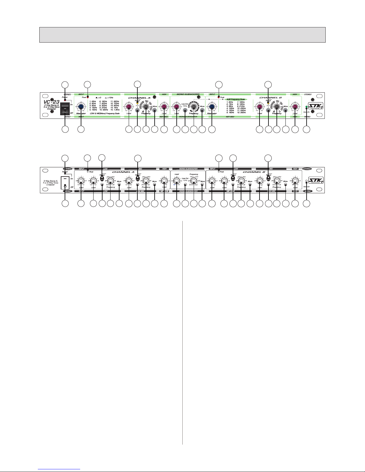
1. Power On/Off Switch
2. Power Indicator LED
3. Channel A Input Level Control
Sets the input sensitivity by attenuating the input signal
strength.
• Stereo: Controls overall input level of channel A without
altering the relative high or low frequency settings.
• Mono: Controls overall input level of entire unit in a
mono conguration without altering the relative high,
mid or low frequency settings.
4. Channel A Peak Indicator LED
• Stereo: The peak indicator LED will begin to illuminate
when the input signal to channel A is within 3 dB of actual
clipping.
• Mono: The peak indicator LED will begin to illuminate
when the mono input signal is within 3 dB of actual
clipping.
5. Channel A Low Frequency Output Level Control
•Stereo: Controls channel A output level of the selected low
frequency range.
•Mono: Controls output level of the selected mono low
frequency range.
6. Frequency Range Selector Switch
Multiplies the frequency selected on the frequency
control(8) by a factor of ten. In the "out" position, the
frequency range is from 60 Hz to 1.3 kHz. In the "in"
position, the frequency range is from 600 Hz to 13 kHz.
7. Frequency Range Indicator LED
The LED will light when the frequency range selector
switch is in the 600 Hz to 13 kHz position.
1. 전원스위치
전원을 공급, 차단하는 스위치입니다.
2. 전원 표시 LED
전원의 ON/OFF상태를 표시하는 LED로서 전원스위치를 ON
시키면 점등됩니다.
3. 채널 A 입력 레벨 조절기
채널 A에 입력되어지는 신호를 조절합니다.
• 스테레오 : 채널 A의 입력레벨을 고나 저 주파수 변화에 상관
없이 조절할 수 있습니다.
• 모노 : 두 채널이 모노로 구성될 때, 고, 중, 저의 주파수 변화
에 상관없이 입력레벨을 조절합니다.
4. 채널 A 피크 표시 LED
• 스테레오 : 이 입력레벨 표시기의 LED에 불이 들어오면 클립
핑이 들어오지 않게 채널 A의 입력 신호를 3dB 이내로 줄이십
시오.
• 모노 : 이 입력레벨 표시기의 LED에 불이 들어오면 클립핑이
들어오지 않게 모노 입력의 신호를 3dB 이내로 줄이십시오.
5. 채널 A 저주파 출력 레벨 조절기
• 스테레오 : 채널 A의 출력의 저음 레벨을 조절합니다.
• 모노 : 모노 출력의 저음 레벨을 조절합니다.
6. 주파수 범위 선택 스위치
주파수 조절기의 10배의 주파수로 증가시킵니다. 이 스위치를
선택하지 않을 경우 주파수 범위가 60Hz에서 1.3kHz이며, 선
택시에는 주파수 범위가 600Hz에서 13kHz가 됩니다.
7. 주파수 범위 표시 LED
이 LED는 주파수 범위가 600Hz에서 1.3kHz 스위치를 선택하
여 사용할 경우 불이 들어옵니다.
8. 채널 A 저주파 선택
3. Panel Descriptions
l
각 부의 명칭
6
A. FRONT PANEL / 전면부 (VC-23, VC-34)
Level
LOW OUTPUT
LOW OUTPUT
Level Level Level
MID OUTPUT
Level
LOW OUTPUT
1 6
7
VC-23
24
3 5 8 9 15 16 18 20 22 25 32 33
21 24
17 19 23 26
VC - 34
3 Way Stereo &
4 or 5 Way Mono
Crossover
1
7
VC-34
24
3 85 96 1514131110
12
16 18 20 2722 3025 32 33
21 2924
17 19 2823 3126

8. Channel A Low Frequency Selector
• Stereo: Selects crossover frequency determining where
the channel A low frequency band terminates and the high
frequency band (VC-23) or the mid frequency band (VC-
34) begins.
• Mono: Selects crossover frequency determining where
the mono low frequency band terminates and the mid
frequency band (VC-23) or low mid frequency band (VC-
34) begins.
9. Channel A Low Frequency Mute Switch
• Stereo: Mutes the signal to channel A low frequency
output.
• Mono: Mutes the signal to mono low frequency output.
10. Channel A Mid Frequency Output Level Control (VC-
34 Only)
• Stereo: Controls the output level of the mid frequency for
channel A.
• Mono: Controls the output level of the low mid frequency
11. Frequency Range Selector Switch (VC-34 Only)
Multiplies the frequency selected on the frequency control
by a factor of ten. In the "out" position, the frequency
range is from 60 Hz to 1.3 kHz. In the "in" position, the
frequency range is from 600 Hz to 13 kHz.
12. Frequency Range Indicator LED (VC-34 Only)
The LED will light when the mid frequency range selector
switch is in the 600 Hz to 13 kHz position.
13. Channel A Mid Frequency Selector (VC-34 Only)
• Stereo: Selects crossover frequency determining where
the channel A mid frequency band terminates and the high
frequency band begins.
• Mono: Selects crossover frequency determining where
the mono low mid frequency band terminates and the high
mid frequency band begins.
14. Channel A Mid Frequency Mute Switch (VC-34 Only)
• Stereo: Mutes the signal to channel A mid frequency
output.
• Mono: Mutes the signal to mono low mid frequency
output.
15. Channel A High Frequency Output Level Control
• Stereo: Controls channel A output level of selected high
frequencies
• Mono: This control is inactive when the VC-23, VC-34 is
used in the mono 3-way or 4-way conguration.
16. Mono Subwoofer Output Level Control
Controls the output level of the selected sub bass frequency
range.
17. High Pass Filter Switch
Enables the high pass lter which will eliminate any
frequencies below 15 Hz.
18. Mono Subwoofer Frequency Selector
Selects crossover frequency determining where the
• 스테레오 : 크로스오버의 주파수 채널 A의 저음 주파수 대역
을 조절합니다.
• 모노 : 크로스오버의 모노의 저음 주파수 대역을 조절합니다.
9. 채널 A 저주파 음소거 스위치
• 스테레오 : 채널 A의 저음 출력신호를 제거합니다.
• 모노 : 모노 저음 출력신호를 제거합니다.
10. 채널 A 중주파 출력 레벨 조절기 (VC-34만 적용)
• 스테레오 : 채널 A의 중음대역의 출력레벨을 조절합니다.
• 모노 : 모노 출력의 중저음대역의 레벨을 조절합니다.
11. 주파수 범위 선택 스위치 (VC-34만 적용)
주파수 조절기의 10배의 주파수로 증가 시킵니다.
이 스위치를 선택하지 않을 경우 주파수 범위가 60Hz에서
1.3kHz이며, 선택시에는 주파수 범위가 600Hz에서 13kHz가
됩니다.
12. 주파수 범위 표시 LED (VC-34만 적용)
이 LED는 주파수 범위가 600Hz에서 1.3kHz 스위치를 선택하
여 사용할 경우 불이 들어옵니다.
13. 채널 A 중주파 선택 (VC-34만 적용)
• 스테레오 : 크로스오버의 주파수 채널 A의 중음 주파수 대역
을 조절합니다.
• 모노 : 크로스오버의 모노사용시 중음 주파수 대역을 조절합
니다.
14. 채널 A 중주파 음소거 스위치 (VC-34만 적용)
• 스테레오 : 채널 A의 중음 출력신호를 제거합니다.
• 모노 : 모노 저음 출력신호를 제거합니다.
15. 채널 A 고주파 출력 레벨 조절기
• 스테레오 : 채널 A의 고음대역의 출력레벨을 조절합니다.
• 모노 : 모노 출력의 고음대역의 레벨을 조절합니다.
16. 모노 서브우퍼 출력 레벨 조절기
초저음의 출력레벨을 조절합니다.
17. 고역필터 스위치
15Hz의 고 Pass Filter를 사용하여 초저음의 노이즈를 제거함
으로써 앰프와 스피커를 보호하실 수 있습니다.
18. 모노 서브우퍼 주파수 선택
크로스오버의 초저음 주파수 대역을 조절합니다.
19. 모노 서브우퍼 주파수 음소거 스위치
초저음 출력신호를 제거합니다.
20. 채널 B 입력 레벨 조절기
채널 B에 입력되어지는 신호를 조절합니다.
• 스테레오 : 채널 B의 입력레벨을 고음이나 저음의 주파수에
상관없이 조절할 수 있습니다.
• 모노 : 이것은 VC-23,VC-34가 모노로 구성되어 사용되어질
때 사용할 수 없습니다.
21. 채널 B 피크 표시 LED
• 스테레오 : 이 입력레벨 표시기의 LED에 불이 들어오면 클립
핑이 들어오지 않게 채널 B의 입력 신호를 30dB 이내로 줄이
십시오.
• 모 노 : 이 입력레벨 표시기는 VC-23, VC-34가 모노로 구
3. Panel Descriptions
l
각 부의 명칭
7
성되어 사용되어질 때는 사용할 수 없습니다.
22. 채널 B 저주파 출력 레벨 조절기
• 스테레오 : 채널 B의 저음대역의 출력을 조절합니다.
• 모 노 : VC-23, VC-34가 모노로 구성되어 사용되어질 때는
사용할 수 없습니다.
23. 주파수 범위 선택 스위치
주파수 조절기의 10배의 주파수로 증가 시킵니다.
이 스위치를 선택하지 않을 경우 주파수 범위가 60Hz에서
1.3kHz이며, 선택시에는 주파수 범위가 600Hz에서 13kHz가
됩니다.
24. 주파수 범위 표시 LED
이 LED는 주파수 범위가 600Hz에서 1.3kHz 스위치를 선택하
여 사용할 경우 불이 들어 옵니다.
25. 채널 B 저주파 선택
• 스테레오 : 크로스오버의 주파수 채널 B의 저음 주파수 대역
을 조절합니다.
• 모 노 : 크로스오버의 모노의 저음 주파수 대역을 조절합니
다. 단, VC-34는 모노로 구성되어질 경우, 사용되어지지 않습
니다.
26. 채널 B 저주파 음소거 스위치
• 스테레오 : 채널 B의 저음 출력신호를 제거합니다.
• 모노 : 모노구성시 저음 출력신호를 제거합니다. 단, VC-34
는 모노로 구성되어질 경우, 사용되어지지 않습니다.
27. 채널 B 중주파 출력 레벨 조절기 (VC-34만 적용)
• 스테레오 : 채널 B의 중음대역의 출력을 조절합니다.
• 모노 : 모노 구성시 고중음 대역의 출력을 조절합니다.
28. 주파수 범위 선택 스위치 (VC-34만 적용)
3. Panel Descriptions
l
각 부의 명칭
8
subwoofer frequency band terminates and the low
frequency band begins.
19. Mono Subwoofer Frequency Mute Switch
Mutes the signal to the mono sub bass output.
20. Channel B Input Level Control
Sets the input sensitivity by attenuating the input signal
strength.
• Stereo: Controls overall input level of channel B without
altering the relative high or low frequency settings.
• Mono: This control is inactive when the VC-23, VC-34 is
used in the mono conguration.
21. Channel B Peak Indicator LED
• Stereo: The peak indicator LED will begin to illuminate
when the input signal to channel B is within 3 dB of actual
clipping.
• Mono: This LED is inactive when the VC-23, VC-34 are
used in the mono conguration.
22. Channel B Low Frequency Output Level Control
• Stereo: Controls channel B output level of the selected
low frequency range.
• Mono: This control is inactive when the VC-23, VC-34 is
used in the mono conguration.
23. Frequency Range Selector Switch
Multiplies the frequency selected on the frequency control
by a factor of ten. In the "out" position, the frequency
range is from 60 Hz to 1.3 kHz. In the "in" position, the
frequency range is from 600 Hz to 13 kHz.
24. Frequency Range Indicator LED
The LED will light when the frequency range selector
A. FRONT PANEL / 전면부 (VC-23, VC-34)
Level
LOW OUTPUT
LOW OUTPUT
Level Level Level
MID OUTPUT
Level
LOW OUTPUT
1 6
7
VC-23
24
3 5 8 9 15 16 18 20 22 25 32 33
21 24
17 19 23 26
VC - 34
3 Way Stereo &
4 or 5 Way Mono
Crossover
1
7
VC-34
24
3 85 96 1514131110
12
16 18 20 2722 3025 32 33
21 2924
17 19 2823 3126

3. Panel Descriptions
l
각 부의 명칭
9
switch is in the 600 Hz to 13 kHz position.
25. Channel B Low Frequency Selector
• Stereo: Selects crossover frequency determining where
the channel B low frequency band terminates and the high
frequency band (VC-23) or the mid frequency band (VC-
34) begins.
• Mono: Selects crossover frequency determining where the
mono mid frequency band ends and the high Frequency
band begins (VC-23). This control is inactive when the VC-
34 is used in the mono conguration.
26. Channel B Low Frequency Mute Switch
• Stereo: Mutes the signal to channel B low frequency
output.
• Mono: Mutes the signal to the mid frequency output (VC-
23). This control is inactive when the VC-34 is used in the
mono conguration.
27. Channel B Mid Frequency Output Level Control (VC-
34 Only)
• Stereo: Controls the output level of the mid frequency for
channel B.
• Mono: Controls the output level of the high mid
frequency.
28. Frequency Range Selector Switch (VC-34 Only)
Multiplies the frequency selected on the frequency
control(30) by a factor of ten. In the "out" position, the
frequency range is from 60 Hz to 1.3 kHz. In the "in"
position, the frequency range is from 600 Hz to 13 kHz
29. Frequency Range Indicator LED (VC-34 Only)
The LED will light when the frequency range selector
switch is in the 600 Hz to 13 kHz position.
30. Channel B Mid Frequency Selector (VC-34 Only)
• Stereo: Selects crossover frequency determining where
the channel B mid frequency band terminates and the high
frequency band begins.
• Mono: Selects crossover frequency determining where the
mono high mid frequency band terminates and the high
frequency band begins.
31. Channel B Mid Frequency Mute Switch (VC-34 Only)
• Stereo: Mutes the signal to the channel B mid frequency
output.
• Mono: Mutes the signal to the mono high mid frequency
output.
32. Channel B High Frequency Output Level Control
• Stereo: Controls channel B output level of selected high
frequencies.
• Mono: Controls output level of selected high frequencies.
33. Mono Mode Indicator LED
When the mode selector switch located on the rear panel is
in the mono position, this LED will light to show that your
VC-23 or VC-34 are operating in the mono mode.
주파수 조절기의 10배의 주파수로 증가 시킵니다.
이 스위치를 선택하지 않을 경우 주파수 범위가 60Hz에서
1.3kHz이며, 선택시에는 주파수 범위가 600Hz에서 13kHz가
됩니다.
29. 주파수 범위 표시 LED (VC-34만 적용)
이 LED는 주파수 범위가 600Hz에서 1.3kHz 스위치를 선택하
여 사용할 경우 불이 들어 옵니다.
30. 채널 B 중 주파수 선택 (VC-34만 적용)
• 스테레오 : 크로스오버 주파수 채널 B의 중음 주파수 대역을
조절합니다.
• 모노 : 크로스오버의 모노의 중음 주파수 대역을 조절합니다.
31. 채널 B 중주파 음소거 스위치 (VC-34만 적용)
• 스테레오 : 채널 B의 중음 출력신호를 제거합니다.
• 모노 : 모노 고중음의 출력신호를 제거합니다.
32. 채널 B 고주파 출력 레벨 조절기
• 스테레오 : 채널 B의 고음대역의 출력레벨을 조절합니다.
• 모노 : 모노 고음대역의 출력레벨을 조절합니다.
33. 모노 모드 표시 LED
이 LED는 뒷면의 모노위치의 스위치를 선택하였을 때 불이 켜
집니다.
10
3. Panel Descriptions
l
각 부의 명칭
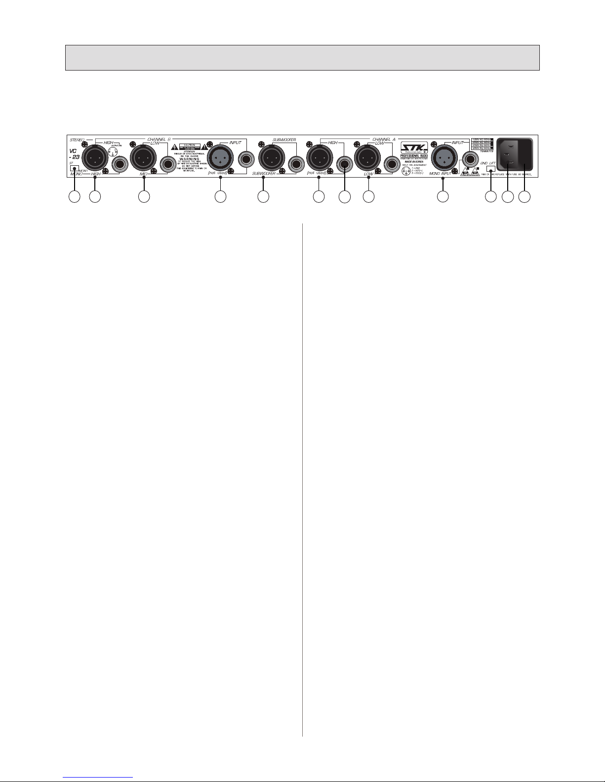
1. Mode Selector Switch
Selects between the stereo 2-way and mono 3-way or
4-way modes of operation.
2. Channel B High Frequency Output (XLR and 1/4″)
• Stereo 2-way: The channel B high frequency signal is
present at this output for connection to the input of the
channel B high frequency amplier.
• Mono: The mono high frequency signal is present at this
output for connection to the input of the high frequency
amplier.
3. Channel B Low Frequency Output (XLR and 1/4″)
• Stereo 2-way: The channel B low frequency signal is
present at this output for connection to the input of the
channel B low frequency amplier.
• Mono 3-way: The mono mid frequency signal is present
at this output for connection to the input of the mid
frequency amplier.
4. Channel B Input
• Stereo 2-way: For stereo operation, the right channel
signal is connected to this input. This jack can also be
used as a second input for parallel mono operation.
• Mono 3-way: This jack is inactive when the VC-23 is
used in the mono conguration.
5. Mono Subwoofer Output
The mono signal from the sub bass lter is present at this
output for connection to the input of the power amplier
to be used to power the subwoofer speaker system. As
this is a mono output, the function is the same no matter
which mode of operation you may choose for the VC-23.
6. Channel A High Frequency Output (XLR and 1/4″)
• Stereo: The channel A high frequency signal is present
at this output for connection to the input of the channel
A high frequency amplier.
• Mono: This jack is inactive when the VC-23 is used in
the mono conguration.
7. Channel A Low Frequency Output (XLR and 1/4″)
• Stereo: The channel A low frequency signal is present at
this output for connection to the input of the channel A
low frequency amplier.
• Mono: The mono low frequency signal is present at this
B. REAR PANEL / 후면부 (VC-23)
VC
- 23
OUTPUT PIN
1=GND
2=HOT(+)
3=COLD(-)
3
2
2 3 5 6 74 8 9 1110
16
1
1. 모드 선택 스위치
스테레오 2-웨이 그리고 3-웨이 모노나 4-웨이 모드를 선택합
니다.
2. 채널 B 고 주파수 출력 (XLR and 1/4″)
• 스테레오 2-웨이 : 채널 B 고주파수 신호는 이 출력부를 통해
고주파 앰프의 입력으로 연결됩니다.
• 모노: 모노 고주파 신호는 이 출력부를 통해 고주파 앰프의
입력부로 연결됩니다.
3. 채널 B 저 주파수 출력 (XLR and 1/4″)
• 스테레오 2-웨이 : 채널 B 저주파 신호는 이 출력부를 통해
고주파 앰프의 입력으로 연결됩니다.
• 모노3-웨이 : 모노 중주파 신호는 이 출력부를 통해 고주파
앰프의 입력부로 연결됩니다.
4. 채널 B 입력
• 스테레오 2-웨이: 스테레오 동작 시, 오른쪽 채널의 신호는
이곳에 연결합니다. 페러럴 모노 동작 시에도 이 잭을 사용합
니다.
• 모노 3-웨이: 모노 구성 시에는 이 잭은 사용하지 않습니다.
5. 모노 서브우퍼 출력
서브 베이스 필터로 부터의 모노 신호를 서브 우퍼 스피커 시
스템의 앰프에 입력할 때 사용하는 단자입니다.
모노 출력이므로, 기기의 다른 모노 운영 방식과 동일하게 작
동합니다.
6. 채널 A 고 주파수 출력 (XLR, 1/4″)
• 스테레오: 이 단자를 통해 채널 A의 고주파 신호를 채널 A의
고주파용 앰프의 입력에 연결합니다.
• 모노: 기기가 모노로 구성될 때에는 이 단자는 사용하지 않습
니다.
7. 채널 A 저 주파수 출력 (XLR, 1/4″)
• 스테레오: 이 단자를 통해 채널 A의 저주파 신호를 채널 A의
저주파용 앰프의 입력에 연결합니다.
• 모노: 모노 저주파 신호는 이 출력부를 통해 저주파 앰프의
입력부로 연결됩니다.
8. 채널 A 입력 (XLR, 1/4″)
• 스테레오: 스테레오 동작 시, 왼쪽 채널의 신호는 이곳에 연
결합니다.
• 모노: 시스템을 모노 구성으로 사용 할 때에 이 단자를 모노
입력으로 사용합니다.

11
12. 모드 선택 스위치
스테레오 3-웨이와 모노 4-웨이 또는 5-웨이의 동작 모드를
선택하는 스위치입니다.
13. 채널 B 고주파 출력
• 스테레오 3-웨이: 채널 B 고주파수 신호는 이 출력부를 통해
고주파 앰프의 입력으로 연결됩니다.
• 모노: 모노 고주파 신호는 이 출력부를 통해 고주파 앰프의
입력부로 연결됩니다.
14. 채널 B 중주파 출력
• 스테레오 : 채널 B 중주파수 신호는 이 출력부를 통해 중주파
앰프의 입력으로 연결됩니다.
• 모노: 모노 중주파 신호는 이 출력부를 통해 중주파 앰프의
입력부로 연결됩니다.
15. 채널 B 저주파 출력
• 스테레오 3-웨이: 채널 B 저주파수 신호는 이 출력부를 통해
저주파 앰프의 입력으로 연결됩니다.
• 모노: 시스템을 모노 구성으로 사용 할 때에 이 단자를 모노
입력으로 사용합니다.
16. 채널 B 입력
• 스테레오: 스테레오 동작 시, 오른쪽 채널의 신호는 이곳에
연결합니다. 페러럴 모노 동작 시에도 이 잭을 사용합니다.
• 모노: 모노 구성 시에는 이 잭은 사용하지 않습니다.
output for connection to the input of the low frequency
amplier.
8. Channel A Input (XLR and 1/4″)
• Stereo: For stereo operation, the left channel signal is
connected to this input.
• Mono: This jack is used as the mono input when the
VC-23 is used in the mono conguration.
9. Ground Lift Switch
Disconnects the signal ground from the AC mains
ground.
10. Power Cord
11. Fuse
Replace only with correct type and rating.
See specications page for this information.
12. Mode Selector Switch
Selects between the stereo 3-way and mono 4-way or
5-way modes of operation.
13. Channel B High Frequency Output
• Stereo 3-way: The channel B high frequency signal is
present at this output for connection to the input of the
channel B high frequency amplier.
• Mono: The mono high frequency signal is present at this
output for connection to the input of the high frequency
amplier.
14. Channel B Mid Frequency Output
• Stereo: The channel B mid frequency signal is present at
this output for connection to the input of the channel B
low frequency amplier.
• Mono: The mono high mid frequency signal is present
at this output for connection to the input of the high mid
frequency amplier.
15. Channel B Low Frequency Output
• Stereo: The channel B low frequency signal is present at
this output for connection to the input of the channel B
low frequency amplier.
• Mono: This jack is inactive when the VC-34 is used in
the mono conguration.
16. Channel B Input
• Stereo: For stereo operation, the right channel signal is
3. Panel Descriptions
l
각 부의 명칭
C. REAR PANEL / 후면부 (VC-34)
20 21 22 23 241912 13 14 15 16 17 18
9. 그라운드 리프트 스위치
신호 접지를 AC 메인 접지와 분리하는 스위치입니다.
10. 전원 코드
11. 퓨즈
퓨즈 교환 시 반드시 표기된 퓨즈와 동일한 규격을 사용하십시
오. 자세한 내용은 제품의 사양을 참고해 주세요.
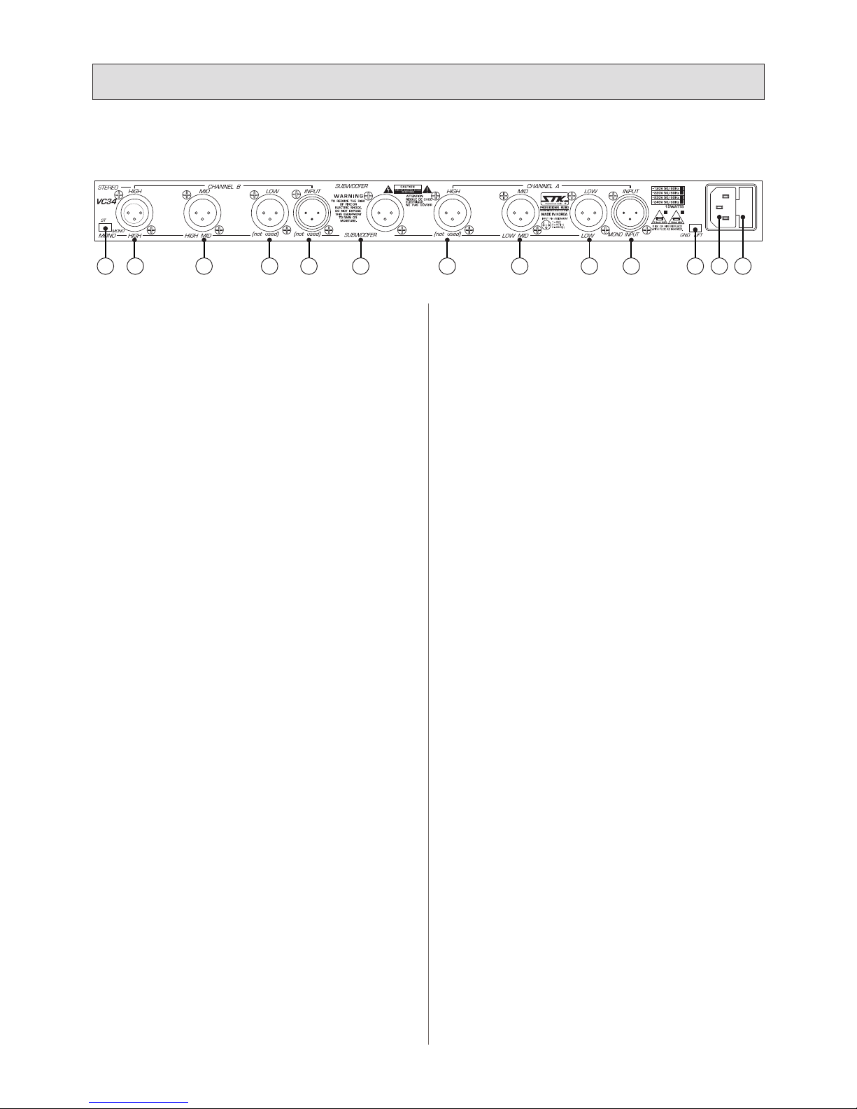
12
connected to this input. This jack can also be used as a
second input for parallel mono operation.
• Mono: This jack is inactive when the VC-34 is used in
the mono conguration.
17. Mono Subwoofer Output
The mono signal from the sub bass lter is present at this
output for connection to the input of the power amplier
to be used to power the subwoofer speaker system. As
this is a mono output, the function is the same no matter
which mode of operation you may choose for the VC-34.
18. Channel A High Frequency Output (XLR)
• Stereo: The channel A high frequency signal is present
at this output for connection to the input of the channel
A high frequency amplier.
• Mono: This output is inactive when the VC-34 is used in
the mono conguration.
19. Channel A Mid Frequency Output
• Stereo: The channel A mid frequency signal is present at
this output for connection to the input of the channel A
mid frequency amplier.
• Mono: The mono low mid frequency signal is present
at this output for connection to the input of the low mid
frequency amplier.
20. Channel A Low Frequency Output
• Stereo: The channel A low frequency signal is present at
this output for connection to the input of the channel A
low frequency amplier.
• Mono: The low mid frequency signal is present at this
output for connection to the low frequency amplier.
21. Channel A Input
• Stereo 3-way: For stereo operation, the left channel
signal is connected to this input.
• Mono: This jack functions as the input when the VC-34
is used in the mono conguration.
22. Ground Lift Switch
Disconnects the signal ground from the AC mains
ground.
23. Power Cord
24. Fuse
Replace only with correct type and rating.
See specications page for this information.
17. 모노 서브우퍼 출력
서브 베이스 필터로 부터의 모노 신호를 서브 우퍼 스피커 시
스템의 앰프에 입력할 때 사용하는 단자입니다.
모노 출력이므로, 기기의 다른 모노 운영 방식과 동일하게 작
동합니다.
18. 채널 A 고주파 출력 (XLR)
• 스테레오: 채널 B 고주파수 신호는 이 출력부를 통해 고주파
앰프의 입력으로 연결됩니다.
• 모노: 모노 구성 시에는 이 잭은 사용하지 않습니다.
19. 채널 A 중주파 출력
• 스테레오 : 채널 A 중주파수 신호는 이 출력부를 통해 중주파
앰프의 입력으로 연결됩니다.
• 모노: 모노 중주파 신호는 이 출력부를 통해 중주파 앰프의
입력부로 연결됩니다.
20. 채널 A 저주파 출력
• 스테레오 : 채널 A 저주파수 신호는 이 출력부를 통해 중주파
앰프의 입력으로 연결됩니다.
• 모노: 모노 중주파 신호는 이 출력부를 통해 중주파 앰프의
입력부로 연결됩니다.
21. 채널 A 입력
• 스테레오 3-웨이: 스테레오 동작 시, 왼쪽 채널의 신호는 이
곳에 연결합니다. 페러럴 모노 동작 시에도 이 잭을 사용합니
다.
• 모노: 시스템을 모노 구성으로 사용 할 때에 이 단자를 모노
입력으로 사용합니다.
22. 그라운드 리프트 스위치
신호 접지를 AC 메인 접지와 분리하는 스위치입니다.
23. 전원 코드
24. 퓨즈
퓨즈 교환 시 반드시 표기된 퓨즈와 동일한 규격을 사용하십시
오. 자세한 내용은 제품의 사양을 참고해 주세요.
3. Panel Descriptions
l
각 부의 명칭
C. REAR PANEL / 후면부 (VC-23)
20 21 22 23 241912 13 14 15 16 17 18

13
A. MOUNTING
The VC-23, VC-34 active stereo crossovers are designed
for standard 19″rack mounting or may be stacked without
a rack cabinet. When rack mounting in conjunction with
other equipment, be sure to allow adequate ventilation of all
components to avoid possible heat related damage to your
crossover or other rack mounted items.
B. OPERATING PRECAUTIONS
Your STK VC-23, VC-34 stereo crossover are well protected
from any external faults. However, we recommend following
these common-sense precautions:
1. Do Not Expose The Unit to Water
Always unplug the unit if water is present. Failure to do so
can result in injury or death from electric shock.
2. Grounding
If your unit is supplied with a grounded power cord and
plug, connect the unit only to a properly grounded AC outlet.
Do not use a ground lift adapter or attempt to defeat the
ground on the plug. Failure to properly ground the unit can
result in damage to it or other equipment connected to it and
represents a dangerous safety hazard.
3. Line Voltage
Operate from AC mains not more than 5% above or below
the specied line voltage and only with the line frequency
specied. Failure to comply may cause serious damage to
your equipment and invalidate the warranty.
4. Pre-Connection Caution
Always switch off the power and set all the level controls to
minimum before making any connections.
This will eliminate any chance of unexpected, loud audio
transients that could damage your speaker systems.
A. 제품 설치
VC-23, VC-34 액티브 스테레오 크로스 오버는 표준 19인치 랙에
장착되는 사이즈입니다. 물론 랙 없이 사용하실 수도 있습니다. 랙
에 장착하여 다른 장비와 함께 사용하실 때에는 장비간 통풍이 잘
되도록 하여 장비에 과열로 인한 손상이 생기지 않도록 주의해 주
십시오.
B. 동작 전 주의 사항
STK VC-23, VC-34 스테레오 크로스 오버는 외부 고장 요소에 잘
보호되도록 설계되어 있지만, 다음의 주의사항을 따라 주신다면 장
비를 오래도록 안전하게 사용하실 수 있습니다.
1. 제품에 물이나 액체를 쏟지 마세요.
장비에 물이나 음료등 액체를 쏟거나, 젖게 하시면 감전으로 인한
사고가 생길 수 있습니다. 장비에 액체가 닿지 않도록 주의해 주십
시오.
2. 접지
만약 전원부가 접지신호를 제공하는 형태라면, 반드시 규격에 맞는
플러그를 사용하시기 바랍니다.
규격과 다른 전원 플러그나 전원코드를 사용하시게 되면 제품과 연
결되어 있는 다른 기기들 역시 전기적 손상을 입을 수 있습니다.
3. 라인 전압
AC 메인 전원은 규정된 전원 용량의 5% 이상이나 이하의 라인 전
압과 라인 주파수만을 사용하십시오.
이를 어길 경우 장비에 치명적인 손상을 가져올 수 있으며, 이 경우
제품 보증 대상에서 제외됩니다.
4. 연결전 주의사항
기기들을 연결하기 전에는 항상 전원을 끈 상태에서 모든 레벨 조
절기를 가장 낮은 위치로 설정하여 주십시오.
이는 기기에서 갑작스럽게 큰 소리가 나는 것을 방지할 수 있는 좋
은 방법입니다.
4. Connecting Your System
l
올바른 설치 방법

14
C. CONNECTORS
Your powered mixers uses several types of input and output
connectors.
1. XLR Input jacks
Electronically balanced inputs accept a standard XLR
male connector. Pin1=ground, pin2=hot or positive(+) and
pin3=cold or negative (-) (see Figure 1). These connectors
should be utilized for low impedance microphones.
If you are using a high impedance microphones, it will likely
have a cord with a 1/4"connector on it. In this case, it would
be appropriate to plug such microphones into a line input,
however performance, and gain may be lessened for best
performance. We recommend you invest in one of the many
higher quality, low impedance mics available on the market,
or alternatively, purchase an impedance matching transformer
from your dealer.
2. 1/4″Phone Input Jacks
These tip/sleeve jacks accept an unbalanced line level signal
using a normal male 1/4″plug. (See Figure1.)
3. XLR Output Jacks
Balanced outputs accept a standard XLR female connector.
Polarity is the same as the inputs.
4. 1/4″Phone Output Jacks
Provide an unbalanced signal using standard tip/sleeve
1/4″plugs.
C. 제품 연결하기
본 기기는 다양한 입, 출력 단자를 가지고 있습니다.
1. XLR 입력 잭
전기적 밸런스드 입력부에 표준형 XLR 돌출형 컨넥터(잭)를 끼웁
니다.
핀1=ground, 핀2=hot 또는 positive(+)
핀3=cold 또는 negative (-) (그림 1 참고).
이 컨넥터(잭)들은 낮은 임피던스의 마이크로폰에 활용됩니다. 높
은 임피던스의 마이크로 폰을 사용하신다면, 1/4"컨넥터(잭)가 장
착된 코드를 사용하시는 것이 좋습니다.
이 경우, 마이크로폰을 라인 입력으로 끼워 충당하는 것이 되며 성
능과 음량은 최대 성능에 못 미치게 줄어들게 됩니다. 고품질의 낮
은 임피던스를 가진 마이크를 사용하시길 권하는 바입니다.
2. 1/4″폰 입력 잭
tip/sleeve 잭에 일반적인 돌출형 폰 플러그를 사용하는 언밸런스
드 라인 레벨 시그널을 끼워 주세요.
(그림 1 참고.)
3. XLR 출력 잭
밸런스드 출력은 표준형 XLR 함몰형 컨넥터에 연결합니다. 극성은
입력 잭과 동일합니다.
4. 1/4″폰 출력 잭
언밸런스드 신호는 tip/sleeve 1/4″플러그로 연결합니다.
4. Connecting Your System
l
올바른 설치 방법
1. GROUND
(shield)
2. HOT +
3. COLD -
12
3
POSITIVE(+)
GROUND(shield)
Figure-1 Audio Connectors ㅣ 그림-1 오디오 연결
a. Female 3 Pin XLR Connector l 함몰형 3핀 XLR 컨넥터 b. Unbalanced 1/4'' Connector l 언밸런스드 1/4'' 컨넥터
15
5. Operating Your System
l
올바른 동작 방법
D. STEREO OPERATION
The STK VC-23 and VC-34 active stereo crossovers are
actually two independent crossovers in one case.
This manual describes the use of one channel of the VC-23
or VC-34 with the assumption that you will make similar
adjustments to the second channel for stereo or parallel mono
applications. Before beginning your connections, you must
decide your mode of stereo operation from these choices:
1. Stereo 2-Way Operation (VC-23)
The normal stereo 2-way system will require the following
equipment to be connected to the outputs of the VC-23:
1 Stereo power amplier to reproduce the high frequencies.
1 Stereo power amplier to reproduce the low frequencies.
2 Two-way speaker systems that have separate inputs available
for the high and low frequencies.
2. Stereo 2-Way Operation With Mono Subwoofer
System (VC-23)
A stereo 2-way with mono subwoofer system would require
the following equipment to be connected to the outputs of
the VC-23.
1 Stereo power amplier to reproduce the high frequencies.
1 Stereo power amplier to reproduce the low frequencies.
2 Two-way speaker systems that have separate inputs available
for the high and low frequencies.
1 Power amplier to reproduce the very low or sub bass
frequencies.
1 or 2 subwoofer speaker systems.
3. Stereo 3-Way Operation (VC-34)
A stereo 3-way system would require the following equipment
to be connected to the outputs of the VC-34.
1 Stereo power amplier to reproduce the high frequencies.
1 Stereo power amplier to reproduce the mid frequencies.
1 Stereo power amplier to reproduce the low frequencies.
2 Three-way speaker systems that have separate inputs
available for the high, mid and low frequencies.
4. Stereo 3-Way Operation With Mono Subwoofer
System (VC-34)
A stereo 3-way with mono subwoofer system would require
the following equipment to be connected to the outputs of
the VC-34.
1 Stereo power amplier to reproduce the high frequencies.
1 Stereo power amplier to reproduce the mid frequencies.
1 Stereo power amplier to reproduce the low frequencies.
2 Three-way speaker systems that have separate inputs
available for the high, mid and low frequencies.
1 Power amplier to reproduce the very low or sub bass
frequencies.
1 or 2 subwoofer speaker systems.
D. 스테레오 동작
STK VC-23과 VC-34 액티브 스테레오 크로스오버는 실질적으로
하나의 케이스에 독립적인 두 개의 크로스오버가 내장되어 있습니
다.
본 사용 설명서는 사용자가 VC-23 또는 VC-34의 다른 채널의 설
정 역시 매뉴얼에 설명된 설정 방법과 비슷하게 설정할 것이라는
가정 하에 하나의 채널을 사용 하는 기본적인 방법을 설명하고 있
습니다.
기기를 연결하기 전에 스테레오 또는 모노 중 한 가지 구성을 먼저
선택해 주세요.
1. 스테레오 2-웨이 동작 (VC-23)
보통의 스테레오 2-웨이 시스템은 다음과 같은 연결을 필요로 합
니다 :
고주파 증폭을 위한 1대의 스테레오 파워 앰프.
저주파 증폭을 위한 1대의 스테레오 파워 앰프.
저주파와 고주파를 나눌 수 있는 2대의 2-웨이 스피커 시스템.
2. 모노 서브우퍼 시스템을 추가한 스테레오 2-웨이 동작
(VC-23)
모노 서브우퍼 시스템과 스테레오 2-웨이 시스템을 함께 사용 할
때에는 VC-23의 출력부에 다음의 장비들을 연결해야 합니다.
고주파 증폭을 위한 1대의 스테레오 파워 앰프.
저주파 증폭을 위한 1대의 스테레오 파워 앰프.
저주파와 고주파를 나눌 수 있는 2대의 2-웨이 스피커 시스템.
매우 낮은 저주파 증폭을 위한 1대의 스테레오 파워 앰프.
서브 우퍼 스피커 1대 또는 2대.
3. 스테레오 3-웨이 동작 (VC-34)
스테레오 3-웨이 시스템은 VC-34 출력단에 다음과 같은 장비들을
연결해야 합니다.
고주파 증폭을 위한 1대의 스테레오 파워 앰프.
중주파 증폭을 위한 1대의 스테레오 파워 앰프.
저주파 증폭을 위한 1대의 스테레오 파워 앰프.
고주파, 중주파, 저주파 분리가 가능한 2대의 3-웨이 스피커 시스
템.
4. 모노 서브우퍼 시스템을 추가한 스테레오 3-웨이 동작
(VC-34)
모노 서브우퍼 시스템을 이용한 스테레오 3-웨이 연결은 다음과
같은 장비가 필요합니다.
고주파 증폭을 위한 1대의 스테레오 파워 앰프.
중주파 증폭을 위한 1대의 스테레오 파워 앰프.
저주파 증폭을 위한 1대의 스테레오 파워 앰프.
고주파, 중주파, 저주파 분리가 가능한 2대의 3-웨이 스피커 시스
템.
매우 낮은 저주파 증폭을 위한 1대의 스테레오 파워 앰프.
서브 우퍼 스피커 1대 또는 2대.

16
5. Operating Your System
l
올바른 동작 방법
E. 시스템 연결
자 이제 스테레오 연결 중 어떤 방식으로 시스템을 구성할지 결정
하셨다면, 시스템 연결과 설정에 대해 알아보겠습니다.
1. 모드 선택 스위치 설정
제품 후면부에 있는 모드 선택 스위치를 스테레오 위치로 선택해
주십시오.
2. 입력단에 오디오 신호 연결하기
믹싱 콘솔이나 스테레오 이퀄라이저 등 외부기기의 오디오 신호를
연결하기 전에 먼저 제품의 전원을 끄고 볼륨을 최하로 낮춰 주십
시오.
신호 장비의 좌측 출력은 크로스오버의 채널 A로, 우측 출력은 크
로스오버의 채널 B로 연결되어야 합니다. 만약 신호 장비의 출력
부가 1/4“폰잭이나 RCA 잭으로 되어 있다면, 크로스오버(VC-23
한정)의 1/4” 잭 입력부로 연결하십시오. 신호 장비의 출력부가
XLR 컨넥터 라면, 크로스오버의 XLR 입력부를 사용하십시오. 일
반적으로 컨넥터의 종류를 동일하게 연결해주는 케이블을 쓰고, 변
환 케이블을 쓰지 않는 것이 가장 높은 품질의 음향을 보장하는 것
으로 알려져 있습니다.
3. 저주파 출력 연결
크로스오버 채널 A의 저주파 출력을 저주파 증폭용 앰프의 좌측이
나 채널 1 입력부로 연결 하십시오.
크로스오버 채널 B의 저주파 출력은 저주파 증폭용 앰프의 우측이
나 채널 2 입력부로 연결 하십시오.
4. 중주파 출력 연결 (VC-34 한정)
크로스오버 채널 A의 중주파 출력을 중주파 증폭용 앰프의 좌측이
나 채널 1 입력부로 연결 하십시오.
크로스오버 채널 B의 중주파 출력은 중주파 증폭용 앰프의 우측이
나 채널 2 입력부로 연결 하십시오.
5. 고주파 출력 연결
크로스오버 채널 A의 고주파 출력을 고주파 증폭용 앰프의 좌측이
나 채널 1 입력부로 연결 하십시오.
크로스오버 채널 B의 고주파 출력은 고주파 증폭용 앰프의 우측이
나 채널 2 입력부로 연결 하십시오.
6. 스피커 동작 모드 설정
액티브 크로스오버를 올바르게 사용하기 위해서, 반드시 저음, 중
음, 고음에 직접 접근할 수 있는 스피커 시스템이 존재해야 합니다.
사용자는 거의 대부분의 스피커 시스템에 조립되어 있는 패시브 크
로스 오버를 통해 바이패스 동작을 할 수 있을 것입니다. 어떤 스
피커의 경우 모드 선택 스위치가 있을 것이고 어떤 스피커는 폰 플
러그를 저/고주파 입력단에 끼우면서 자동 선택이 될 것입니다. 만
약 사용하시는 스피커 시스템이 바이-앰프, 트라이-앰프, 또는 풀-
레인지 모드로 선택할 수 있는 스위치가 있는 모델이라면, 스위치
를 바이-앰프(VC-23), 트라이- 앰프(VC-34) 로 설정하여 주십시
오.
중요한 사항:
모드 선택 스위치를 올바르게 설정하지 못하면, 스피커나 앰프에
치명적인 손상을 입힐 수 있습니다. 만약 스피커 설정을 잘 모르시
E. SYSTEM CONNECTION
Now that you have decided which mode and type of system
operation you will use, you are ready to make your system
connections and settings on your STK crossover.
1. Set Mode Selector Switch
Set the mode selector switch on the rear panel to the stereo
position.
2. Connect Audio Source To Inputs
With the input and output level controls on your VC-23
or VC-34 set to minimum and the power off, connect the
outputs of your source device, such as a mixing console or
stereo graphic equalizer to the inputs of the crossover. The
left channel output of the source device should be connected
to channel A and the right channel output connected to
channel B of the crossover. If the outputs of the source
device are 1/4″ phone jacks or RCA pin jacks, use the
1/4″inputs on the crossover(VC-23 only). If the outputs of
the source device are XLR connectors, use the XLR inputs
on the crossover. It is generally accepted that for best results,
the type of connection should be uniform from one device
to the next and you should not use cables with different
connectors on each end such as an unbalanced phone plug on
one end and an XLR on the other.
3. Connect Low Frequency Output
Connect the channel A low frequency output of the crossover
to the left or channel 1 input of the low frequency power
amplier. Connect the channel B low frequency output to the
right or channel 2 input of the low frequency amplier.
4. Connect Mid Frequency Output (VC-34 only)
Connect the channel A mid frequency output of the crossover
to the left or channel 1 input of the mid frequency power
amplier. Connect the channel B mid frequency output to
the right or channel 2 input of the mid frequency amplier.
5. Connect High Frequency Output
Connect the channel A high frequency output of the
crossover to the left or channel 1 input of the high frequency
power amplier. Connect the channel B high frequency
output to the right or channel 2 input of the high frequency
power amplier.
6. Set Speaker Operation Mode
In oder to properly use an active crossover, you must have
speaker systems that are equipped to allow direct access to
the low, mid and high frequency components of the speaker
system. You must be able to bypass the built-in, passive
crossover found in almost all speaker systems. A mode switch
will be found on some speaker systems while others may
have automatic switching which takes place when you insert a
phone plug into the low and/or high frequency input jacks. If

17
your speaker systems have a switch to select the bi-amp, tri-
amp or full range modes, set the switch to the bi-amp (VC-23)
or tri-amp (VC-34) mode now.
Important:
Failure to properly set the speaker mode switch could cause
damage to your speaker system and/or power amplier. If
you are unsure as to how to set up your speaker systems
for bi-amp or tri-amp operation, please ask your SoundLab
dealer for help.
7. Connect Low Frequency Speaker
Connect the left, or channel 1, speaker output from the low
frequency power amplier to the low frequency speaker input
of your left side speaker system. Connect the right, or channel
2, speaker output from the low frequency power amplier
to the low frequency speaker input of your right side speaker
system.
8. Connect Mid Frequency Speaker or Driver
(VC-34 Only)
Connect the left, or channel 1, speaker output from the mid
frequency power amplier to the mid frequency input of
your left side speaker system. Connect the right, or channel
2, speaker output from the mid frequency power amplier to
the mid frequency input of your right side speaker system.
9. Connect High Frequency Driver
Connect the left, or channel 1, speaker output from the high
frequency power amplier to the high frequency input of
your left side speaker system. Connect the right, or channel
2, speaker output from the high frequency power amplier to
the high frequency input of your right side speaker system.
Note:
if you will be using a subwoofer system with either the VC-
23 or VC-34 the following additional steps are necessary in
setting up your system before switching on the power.
10. Connect Subwoofer Output
Connect the mono subwoofer output of your crossover to the
input of your subwoofer amplier.
The sub bass output is mono as low frequencies are omni-
directional. Stereo imaging is not perceptible in the
subwoofer frequency range. Therefore the only advantage
of using more than one subwoofer is for additional power
handing capability. If you will be using more than one
subwoofer speaker system, you can use a stereo power
amplier with the inputs paralleled.
11. Connect Subwoofer Speaker Systems
Connect the output of your sub bass frequency power
amplier to the input of your subwoofer speaker system.
5. Operating Your System
l
올바른 동작 방법
겠다면, 구매하신 대리점에 문의하시길 바랍니다.
7. 저주파 스피커 연결
스피커 시스템의 좌측, 또는 채널 1의 입력부에 저주파 앰프의 출
력을 연결합니다.
스피커 시스템의 우측, 또는 채널 2의 입력부에 저주파 앰프의 출
력을 연결합니다.
8. 중주파 스피커나 드라이버 연결(VC-34 한정)
스피커 시스템의 좌측, 또는 채널 1의 입력부에 중주파 앰프의 출
력을 연결합니다.
스피커 시스템의 우측, 또는 채널 2의 입력부에 중주파 앰프의 출
력을 연결합니다.
9. 고주파 드라이버 연결
스피커 시스템의 좌측, 또는 채널 1의 입력부에 고주파 앰프의 출
력을 연결합니다.
스피커 시스템의 우측, 또는 채널 2의 입력부에 고주파 앰프의 출
력을 연결합니다.
참고사항:
VC-23 이나 VC-34와 함께 서브 우퍼 시스템을 사용하실 거라면
제품의 전원을 켜기 전에 다음의 추가적인 순서를 지켜 주세요.
10. 서브우퍼 출력 연결
크로스 오버의 모노 서브 우퍼 출력을 서브우퍼 앰프의 입력부로
연결합니다.
서브 베이스 출력은 전방향식 저음으로서의 모노입니다. 인간은 서
브우퍼의 주파수 영역에서는 스테레오의 느낌은 감지할 수가 없습
니다. 그러므로 한 대 이상의 서브 우퍼를 사용하는 것은 파워를
높이는 정도의 장점밖에는 제공하지 못합니다. 만약 한 대 이상의
서브우퍼를 사용하실 의향이라면, 스테레오 앰프의 입력을 병렬로
사용하시는 것이 좋습니다.
11. 서브우퍼 스피커 시스템 연결
서브 베이스 주파수의 앰프의 출력을 서브 우퍼 스피커 시스템의
입력부로 연결하세요.

18
5. Operating Your System
l
올바른 동작 방법
F. SYSTEM ADJUSTMENT
Now that you have integrated your VC-23 or VC-34 into
your sound system as recommended, carefully follow the
instructions in the next section in order to get the full benet
from your new active crossover.
Important:
The most important adjustment on your crossover is the
frequency selector control to select the low to high frequency
crossover point on the VC-23 and the same controls on the
VC-34 to select low to mid and mid to high crossover points.
Before setting your crossover frequencies, refer to the back
panel of your speaker system or the manual supplied with
your speaker system to nd the manufacturer's recommended
crossover points. Improper adjustment of your crossover
may lead to speaker component damage. While the various
adjustments of your active crossover will affect the tonality
of your sound system, your electronic crossover is not a tome
control for your sound system and should not be used as
such.
1. Check System Power Switches
Begin by making sure that all components are still switched
off and all level controls are set at minimum or hard left
position.
2. Set Crossover Frequency
On the front panel, turn your channel A low/high
(VC-23) or low/mid (VC-34) frequency control to the
crossover frequency recommended by your speaker system
manufacturer as outlined above.
This frequency will be the minimum at which your high (VC-
23) or mid (VC-34) frequency speaker can safely operate. You
may wish to raise that frequency point, however, you should
not operate output of the parameters set forth in your speaker
manual. If you do not know the recommended crossover
frequency of your speaker systems, you should contact the
manufacturer or your dealer.
Caution:
Failure to properly set this control will cause damage to your
speaker systems.
By setting this control, you have now routed the frequencies
above the crossover point to the high frequency output
of the VC-23 or the mid frequency output of the VC-34.
Frequencies below the crossover point will be sent to the low
frequency output.
3. Check Frequency Range Selector Switch
The yellow indicator light will indicate the crossover
frequency range selector switch is in the "in" position once
power has been switched on. Check this for the proper
setting of your selected crossover frequency.
Remember, the ×10 switch multiplies the selected crossover
1. 시스템 전원 스위치 확인
시작하기에 앞서 모든 장비의 전원이 꺼져 있는지 확인하고 모든
볼륨 조절기가 최저 수준인지 확인해 주십시오.
2. 크로스오버 주파수 설정
전면부의 채널 A의 저/고주파(VC-23) 또는 저/중주파(VC-34) 조
절기를 스피커 제조사에서 권장한 크로스 오버 주파수로 맞춰주십
시오.
이 주파수는 고주파(VC-23) 또는 저주파(VC-34) 스피커가 안전
하게 동작할 수 있는 최소 주파수가 될 것입니다. 그러나, 주파수
포인트를 올리고 싶더라도, 스피커 매뉴얼 대로의 설정 값을 조정
하여서는 안됩니다. 만약 스피커 시스템에서의 권장 크로스오버 주
파수를 모르신다면, 스피커 제조사나 담당 판매자에게 문의하여 주
십시오.
주의 사항:
본 설정을 적절하게 하지 못할 경우 스피커 시스템에 손상이 생길
수 있습니다.
본 설정은 크로스오버 주파수 포인트로부터 VC-23의 고주파 출력
이나 VC-34의 중주파 출력으로의 통로를 만들게 되는 것입니다.
크로스오버 포인트 이하의 주파수는 저주파 출력으로 나가게 됩니
다.
3. 주파수 범위 선택 스위치 확인
노란색 표시등은 크로스오버 주파수 선택 스위치가 눌려진 상태일
때 켜지게 됩니다. 크로스오버 설정을 하기 전에 먼저 표시등이 점
등되어 있는지 확인해 주세요.
x10 스위치는 선택된 크로스오버 주파수를 10배로 높인다는 것을
기억하세요.(70 Hz 는 700 Hz가 됩니다).
주파수 조절시 부적절한 주파수 범위 스위치 설정은 기기에 문제를
일으킬 수 있습니다. VC-23은 18번 단계로 가 주십시오.
4. 채널 A 중/고 크로스 오버 주파수 선택 (VC-34 한정)
전면부 채널 A 중/고 주파 설정을 권장 크로스오버 주파수로 맞춰
주세요.
이 주파수는 고주파 스피커나 트위터가 안전하게 동작할 수 있는
최소값입니다.
F. 시스템 세부 조정
자, 이제 VC-23이나 VC-34를 사운드 시스템에 연결했다면, 매뉴
얼의 다음 부분을 참고하여 크로스오버를 올바르고 알차게 사용할
수 있도록 해 주십시오.
중요사항:
VC-23 크로스오버에서 가장 중요한 설정은 저주파에서 고주파까
지 크로스 오버 포인트를 선택하는 것 입니다. VC-34의 경우는
저주파에서 중간주파수, 중간주파수에서 고주파 까지의 크로스 오
버 포인트를 설정합니다. 크로스 오버 주파수를 설정하기 이전에
스피커의 뒷면이나 사용자 매뉴얼을 참고하여 스피커 제조사가 추
천하는 크로스 오버 포인트를 찾아주십시오. 크로스 오버의 옳지
못한 설정값은 스피커에 손상을 입힐 수 있으니 주의하십시오. 액
티브 크로스오버 기기를 통해 다양한 크로스 오버 포인트를 조절하
게 되면 사운드 시스템의 음색을 더욱 풍부하게 할 수 있습니다. 크
로스오버기기는 음향의 톤을 조절하거나 그러한 용도로 사용하는
것이 아닙니다.

19
5. Operating Your System
l
올바른 동작 방법
frequency 10 times (70 Hz becomes 700 Hz).
As with the frequency control, improper setting of the range
switch could cause damage to your speaker
system when power si switched on. If you are using an VC-
23, proceed to step 18.
4. Select Channel A Mid/High Crossover Frequency
(VC-34 Only)
On the front panel, turn your channel A mid/high frequency
control to the recommended crossover frequency.
This frequency will be the minimum at which your high
frequency speaker or tweeter can safely operate.
You may wish to raise that frequency point, however, you
should never operate below the limit set forth in your speaker
manual. If you do not know the recommended crossover
frequency of your speaker systems, you should contact the
manufacturer or your dealer. Failure to properly set this
control will cause damage to your speaker systems. By setting
this control, you have now routed the frequencies above the
selected crossover point to the high frequency output of the
VC-34 frequencies below the crossover point will be sent to
the mid frequency output.
5. Check Frequency Range Selector Switch
The yellow indicator light will indicate the crossover
frequency range selector switch is in the "in" position once
power has been switched on. Check this for the proper
setting of your selected crossover frequency.
Remember, the ×10 switch multiplies the selected crossover
frequency 10 times (70 Hz becomes 700 Hz).
Note:
Steps 18 through 20 refer to mono subwoofer operation. If
you do not intend to use the subwoofer section, set the input
and output level controls at minimum and keep them at this
setting.
6. Mono Subwoofer Output
If you will use the mono subwoofer facility, connect the
subwoofer output of your crossover to the input of your
subwoofer amplier as described above. If you haven't already
done so, connect the subwoofer amplier output to the input
of your subwoofer speaker system.
7. Select Subwoofer Crossover Frequency
Select the subwoofer crossover frequency as you did with
the high and low frequency controls. Consult the manual
supplied with your subwoofer or look at the back plate on the
speaker to determine the optimum crossover sitting. If no
information is available, set the crossover frequency to 150
Hz.
그러나, 주파수 포인트를 올리고 싶더라도, 스피커 매뉴얼 대로의
설정 값을 조정하여서는 안됩니다. 만약 스피커 시스템에서의 권장
크로스오버 주파수를 모르신다면, 스피커 제조사나 담당 판매자에
게 문의하여 주십시오.
본 설정을 적절하게 하지 못할 경우 스피커 시스템에 손상이 생길
수 있습니다.
본 설정은 크로스오버 주파수 포인트로부터 VC-34의 중주파 출력
으로의 통로를 만들게 되는 것입니다. 크로스오버 포인트 이하의
주파수는 저주파 출력으로 나가게 됩니다.
5. 주파수 범위 선택 스위치 확인
노란색 표시등은 크로스오버 주파수 선택 스위치가 눌려진 상태일
때 켜지게 됩니다. 크로스오버 설정을 하기 전에 먼저 표시등이 점
등되어 있는지 확인해 주세요.
x10 스위치는 선택된 크로스오버 주파수를 10배로 높인다는 것을
기억하세요.(70 Hz 는 700 Hz가 됩니다).
참고사항:
18번부터 20번까지의 단계는 모노 서브우퍼 동작에 관한 설명입
니다. 만약 서브우퍼를 사용하지 않으신다면 입,출력 레벨 컨트롤
을 최하로 낮춰주시고 그 설정을 유지하여 주십시오.
6. 모노 서브우퍼 출력
모노 서브우퍼 설비를 사용할 때에는 위에 설명한 것과 같이 크로
스오버의 출력을 서브우퍼 앰프의 입력으로 연결하세요. 연결을 마
치셨다면, 서브우퍼 앰프의 출력을 서브우퍼 스피커 시스템의 입력
으로 연결하여 주십시오.
7. 서브우퍼 크로스 오버 주파수 선택
서브우퍼 크로스오버 주파수의 선택은 고, 저주파 조절기로 할 수
있습니다.
서브 우퍼 스피커의 매뉴얼이나 서브우퍼 후면의 최적 크로스오
버 설정값을 참고하여 크로스오ㅂ 주파수를 설정하여 주십시오.
만약 아무런 설정값에 대한 정보가 없다면, 크로스오버 주파수를
150Hz로 설정하여 주십시오.
8. 하이-패스 필터 동작준비
STK 크로스오버에는 서브우퍼 섹션에 하이패스 필터가 내장되어
있습니다. 이 필터는 15Hz 미만의 신호는 깔끔하게 깍아내 줍니
다. 그런 낮은 주파수 스펙트럼에는 귀로 들을 수 있는 소리가 거의
없기 때문에 이 필터를 사용하게되면, 과한 저주파로 인한 서브우
퍼의 손상을 막을 수 있습니다.
하이패스 필터를 동작시키려면, 하이패스 스위치를 눌려진 상태가
되도록 해주세요.
9. 시스템 게인
계속하기 전에 본 매뉴얼의 “전문적인 동작을 위한 팁” 부분을 읽
고 따라 주세요. 사운드 시스템을 동작시킬 때 각 장비의 게인 구조
와 순서를 이해하는 것은 매우 중요합니다. 특히 이 장비를 사용할
때에는 더더욱 그렇습니다.
위 섹션에서 올바른 게인 조절 절차를 알려드리겠습니다. 22번 단
계에 설명된 것과 같이 시스템의 전원을 올리시고 신호 기기에 따
른 전체 시스템에서 크로스오버까지의 각 레벨과 게인 구조를 설립
하여 주십시오.
`

20
5. Operating Your System
l
올바른 동작 방법
8. Engage Hi-Pass Filter
Your STK crossover is tted with a high pass lter in the
subwoofer section. This lter sharply rolls off the signal
below 15 Hz. As there are no audible sound located that low
in the frequency spectrum, using this feature will protect
your drivers from subsonic, over-excursion damage.
To engage the high pass lter, depress the high pass switch to
the "in" position.
9. System Gain
Before proceeding, refer to section "Professional Operating
Tips" in this manual. It is important that you understand
proper gain structure procedures when using any sound
system. It is of particular importance when using this device.
This section will help you learn correct gain adjustment
procedures. Once you have powered up the system as
described in step 22, establish the levels and gain structure
for your whole system up to the crossover per the instructions
for your source devices, mixing console and other signal
processing.
10. Switching On Power
At this time, you may now switch on all equipment up to and
including your crossover, but do not switch on the power
ampliers. Before doing so, check once more that your input
and output level controls are turned hard left, or to the off
position. As you are operating in the stereo mode, the mono
mode indicator light on your VC-23 or VC-34 should not be
illuminated.
11. Set Input Level Controls
Now you are ready to make the level adjustments for your
VC-23 or VC-34 with your ampliers still off, play some
program material from your source. The signal from your
last piece of equipment such as a graphic equalizer should be
strong. With your program material reaching the occasional
peak, slowly turn the input level controls for channel A and
channel B up individually. Increase the levels until you see
the red peak indicators located on the front panel begin to
ash. These should only illuminate on program peaks.
The input level controls are now correctly adjusted.
12. Set Output Level Controls
The unity gain position (unity gain means the output level
is the same as the input level)on your crossover is at the "0"
point on the output level controls. There is a detente at this
point. In order to maintain proper gain structure, you should
place the output controls in this detente or "0" position as a
starting point. Further adjustment may be necessary later.
13. Recheck Power Amplier Connections
Before switching on your ampliers, double check all your
input and speaker connections.
Once all connections have been veried, check to see that
10. 전원 넣기
이번에는 파워앰프를 제외한 크로스오버를 포함한 모든 장비의 스
위치를 켜주십시오. 물론 그전에 모든 입력 기기와 출력 기기의 볼
륨 조절기가 최하의 위치로 되어있는지 한번 더 확인해 주십시오.
스테레오로 동작 시키실 때에는 물론 모노 동작 표시등이 켜지지
않아야 합니다.
11. 입력 레벨 조절기 설정
앰프의 전원이 여전히 꺼져있는 상태에서 VC-23과 VC-34의 레
벨 조절을 할 준비가 되어 있다면, 신호 기기를 동작 시켜 주십시
오. 그래픽 EQ와 같은 마지막 장비의 신호는 꽤 강력할 것입니다.
신호 기기가 이따금 피크에 도달하면, 채널 A와 B 각각의 레벨 조
절기를 낮춰 주십시오. 그리고 다시 전면부의 붉은색 피크 표시등
이 깜박일 때까지 천천히 레벨 조절기를 올려 주십시오. 이것은 단
지 프로그램 피크에 대한 것입니다.
이제 입력 레벨 조절기는 올바르게 설정되었습니다.
12. 출력 레벨 조절기 설정
크로스 오버의 유니티 게인 위치(유니티 게인이란 입력 레벨과 출
력 레벨이 동일한 게인을 말합니다.)는 출력 레벨 조절기의 "0"위치
입니다. 그 부분에 조절기가 살짝 걸리는 부분이 있습니다. 올바른
게인 구조를 유지하기 위해 출력 조절기를 이 위치 또는 "0"의 위치
에 두고 시작하셔야 합니다. 추가적인 조절은 차후에 필요하게 될
것입니다.
13. 파워 앰프 연결 재확인
앰프의 전원을 켜기 전에 입력 기기들과 스피커들의 연결 상태를
다시 한번 확인해 주십시오.
모든 연결이 확인 되었다면, 앰프의 입력 레벨이 여전히 가장 낮은
위치로 되어있는지 확인하여 주십시오. 확인이 끝나면, 모든 앰프
의 전원을 켜 주십시오.
14. 앰프의 입력 레벨 조절기 설정
일반적으로 파워 앰프로 신호를 입력하는 기기가 앰프를 최대 파워
로 동작 시킬 수 있을 만큼 충분한 출력 게인을 가지지 못했다면 파
워 앰프의 레벨 조절은 최대로 할 필요가 없습니다.
VC-23, VC-34는 많은 출력단을 가지고 있습니다. 시스템을 테스
트할 때는 올바른 시스템 설정과 균형을 확보할 때까지 앰프 레벨
을 다른 기기에 비해 낮게 유지해 주십시오.
이를 통해 갑작스러운 과신호로부터 스피커 시스템을 보호할 수 있
습니다.
15. 음소거 스위치
음소거 스위치는 시스템 설치 시 유용한 도구가 될 수 있습니다.
VC-23은 스테레오 동작 모드에서 저주파 출력 을 음소거 할 수 있
습니다. VC-3은 저주파, 또는 중주파, 그리고 저, 중주파 모두 음
소거 할 수 있습니다.
STK 크로스오버에는 서브우퍼 섹션을 포함하여 각 채널마다 음소
거 버튼이 있습니다.
이 스위치들을 활용하는 것은 각 스피커의 기능을 출력 레벨의 변
경 없이 확인 할 수 이게 해주는 것입니다. 또한, 각 스피커 시스템
의 드라이버가 올바르게 동작하고 있는지를 다른 스피커들을 음소
거 함으로써 일일이 가서 들어보지 않아도 되도록 활용할 수 있습
니다. 음소거 스위치는 스위치가 눌려져있을 때 동작합니다.
This manual suits for next models
1
Table of contents


