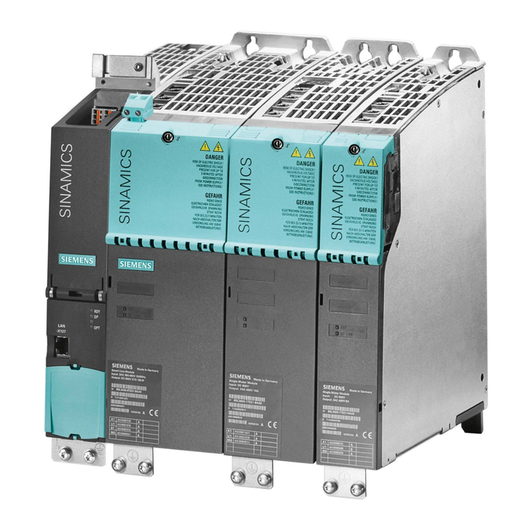
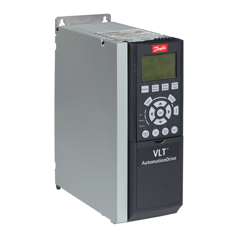
Stober PS6 Series User manual

Multi-axis drive system with SI6 and PS6
Manual
en-US
02/2019
ID 442728.05
stober.com

Table of contents STOBER
ii
02/2019 | ID 442728.05
Table of contents
1 Foreword .............................................................................................................................. 9
2 User information................................................................................................................ 10
2.1 Storage and transfer ...................................................................................................10
2.2 Described product type...............................................................................................10
2.3 Timeliness...................................................................................................................10
2.4 Original language........................................................................................................10
2.5 Limitation of liability.....................................................................................................10
2.6 Formatting conventions ..............................................................................................11
2.6.1 Use of symbols............................................................................................. 11
2.6.2 Markup of text elements ............................................................................... 12
2.6.3 Conventions for cables................................................................................. 13
2.7 Symbols, marks and test symbols ..............................................................................13
2.8 Trademarks.................................................................................................................14
3 General safety instructions .............................................................................................. 15
3.1 Directives and standards ............................................................................................15
3.2 Qualified personnel.....................................................................................................15
3.3 Intended use ...............................................................................................................15
3.4 Transport and storage ................................................................................................16
3.5 Operational environment and operation .....................................................................16
3.6 Working on the machine .............................................................................................17
3.7 Disposal......................................................................................................................18
3.8 Firefighting..................................................................................................................18
4 UL-compliant use .............................................................................................................. 19
5 System configuration........................................................................................................ 22
5.1 Hardware components................................................................................................23
5.1.1 Supply module.............................................................................................. 23
5.1.2 Drive controller ............................................................................................. 27
5.1.3 DC link connection........................................................................................ 31
5.1.4 Controller...................................................................................................... 32
5.1.5 Operating motors, encoders and brakes ...................................................... 33
5.1.6 Accessories .................................................................................................. 34
5.2 Software components .................................................................................................37
5.2.1 Project configuration and parameterization.................................................. 37
5.2.2 Applications .................................................................................................. 37

STOBER Table of contents
02/2019 | ID 442728.05
iii
6 Technical data.................................................................................................................... 38
6.1 General technical data................................................................................................38
6.2 Supply module ............................................................................................................39
6.2.1 Electrical data............................................................................................... 39
6.2.2 Dimensions................................................................................................... 42
6.2.3 Weight .......................................................................................................... 42
6.3 Drive controllers..........................................................................................................43
6.3.1 Electrical data............................................................................................... 43
6.3.2 Derating........................................................................................................ 51
6.3.3 Dimensions................................................................................................... 53
6.3.4 Weight .......................................................................................................... 54
6.4 DC link connection......................................................................................................54
6.4.1 General technical data.................................................................................. 54
6.4.2 DL6B assignment – SI6 and PS6................................................................. 55
6.4.3 Dimensions................................................................................................... 55
6.4.4 Weight .......................................................................................................... 56
6.5 Safety technology .......................................................................................................57
6.6 Operating motors ........................................................................................................58
6.7 Evaluable encoders ....................................................................................................59
6.7.1 Overview....................................................................................................... 59
6.7.2 Signal transmission ...................................................................................... 59
6.7.3 X4 ................................................................................................................. 60
6.7.4 X101 for encoders ........................................................................................ 63
6.7.5 X103 for encoders ........................................................................................ 63
6.8 Controllable brakes.....................................................................................................64
6.9 Braking resistor...........................................................................................................65
6.9.1 Braking resistor assignment – PS6 .............................................................. 65
6.9.2 KWADQU flat resistor................................................................................... 65
6.9.3 FZZMQU tubular fixed resistor ..................................................................... 67
6.9.4 FGFKQU steel-grid fixed resistor ................................................................. 69
6.10 Choke .........................................................................................................................71
6.10.1 TEP output choke......................................................................................... 71
7 Project configuration ........................................................................................................ 76
7.1 Supply module ............................................................................................................76
7.1.1 Information on design and operation............................................................ 76
7.1.2 Parallel connection of supply modules ......................................................... 77
7.2 DC link connection......................................................................................................78
7.2.1 Information on design and operation............................................................ 78
7.3 Mixed operation ..........................................................................................................79

Table of contents STOBER
iv
02/2019 | ID 442728.05
7.4 Example design for UL-compliant operation...............................................................80
7.4.1 Maximum operation on PS6A24................................................................... 81
7.4.2 Maximum operation on PS6A34................................................................... 82
7.4.3 Sample calculation ....................................................................................... 83
7.5 Order overview of the hardware components.............................................................83
8 Storage ............................................................................................................................... 85
8.1 Supply module ............................................................................................................85
8.2 Drive controller............................................................................................................85
8.2.1 Annual reforming .......................................................................................... 86
8.2.2 Reforming before commissioning................................................................. 87
9 Installation.......................................................................................................................... 89
9.1 Safety instructions for installation ...............................................................................89
9.2 Basic assembly instructions........................................................................................89
9.2.1 Drive controllers and supply modules........................................................... 89
9.2.2 Choke ........................................................................................................... 90
9.2.3 Braking resistor............................................................................................. 90
9.3 Minimum clearances...................................................................................................92
9.4 Drilling diagrams and dimensions...............................................................................93
9.4.1 Multi-axis drive system ................................................................................. 93
9.5 Length of copper rails .................................................................................................94
9.6 Installing the DC link connection.................................................................................95
9.6.1 Order overview of the components for the DC link connection .................... 95
9.6.2 Installing the DC link connection .................................................................. 95
9.7 Installing drive controllers and supply modules ..........................................................99
10 Connection....................................................................................................................... 102
10.1 Safety instructions for connection.............................................................................102
10.2 Line routing...............................................................................................................103
10.3 Protective measures.................................................................................................103
10.3.1 Power grid supply....................................................................................... 103
10.3.2 CE-compliant line fuse................................................................................ 104
10.3.3 UL-compliant line fuse................................................................................ 105
10.3.4 Grid connection .......................................................................................... 105
10.3.5 Residual current protective device ............................................................. 105
10.3.6 CE-compliant housing grounding ............................................................... 107
10.3.7 UL-compliant housing grounding................................................................ 108
10.3.8 EMC recommendations.............................................................................. 109
10.4 Supply module..........................................................................................................110
10.4.1 Overview..................................................................................................... 110
10.4.2 X10: 400V supply ...................................................................................... 111
10.4.3 X11: 24V supply ........................................................................................ 112

STOBER Table of contents
02/2019 | ID 442728.05
v
10.4.4 X21: Braking resistor .................................................................................. 113
10.4.5 X22: DC link connection ............................................................................. 113
10.4.6 X23: Temperature monitoring of braking resistor ....................................... 114
10.4.7 X100: Status output.................................................................................... 114
10.4.8 Connecting the supply module ................................................................... 115
10.5 Drive controller..........................................................................................................116
10.5.1 Overview..................................................................................................... 116
10.5.2 X2A: Brake A.............................................................................................. 117
10.5.3 X2A: Motor temperature sensor A.............................................................. 118
10.5.4 X2B: Brake B.............................................................................................. 119
10.5.5 X2B: Motor temperature sensor B.............................................................. 119
10.5.6 X4A: Encoder A.......................................................................................... 119
10.5.7 X4B: Encoder B.......................................................................................... 124
10.5.8 X9: Ethernet service interface .................................................................... 124
10.5.9 X11: 24V supply ........................................................................................ 125
10.5.10 X12: Safety technology (SR6 option) ......................................................... 126
10.5.11 X20A: Motor A ............................................................................................ 127
10.5.12 X20B: Motor B ............................................................................................ 128
10.5.13 X22: DC link connection ............................................................................. 128
10.5.14 X101: BE1 – BE4........................................................................................ 130
10.5.15 X103: BE6 – BE9........................................................................................ 131
10.5.16 X200, X201: EtherCAT............................................................................... 133
10.5.17 X200, X201: PROFINET............................................................................. 134
10.5.18 X300: Brake 24V supply............................................................................ 135
10.5.19 X700: SD slot.............................................................................................. 136
10.5.20 Connecting a drive controller...................................................................... 137
10.6 Output choke ............................................................................................................138
10.6.1 Connection description............................................................................... 138
10.7 Cables.......................................................................................................................140
10.7.1 Power cables.............................................................................................. 141
10.7.2 Encoder cables........................................................................................... 145
10.7.3 One Cable Solution .................................................................................... 155
11 Commissioning................................................................................................................ 159
11.1 Initiating the project...................................................................................................159
11.1.1 Projecting the drive controller and axis....................................................... 159
11.1.2 Configuring the safety module.................................................................... 161
11.1.3 Creating other modules and drive controllers............................................. 161
11.1.4 Specifying a module ................................................................................... 161
11.1.5 Specifying the project ................................................................................. 162
11.2 Mechanical drive model............................................................................................162
11.2.1 Parameterizing the STOBER motor ........................................................... 162
11.2.2 Parameterizing the axis model ................................................................... 163
11.3 Testing the project configuration...............................................................................165

Table of contents STOBER
vi
02/2019 | ID 442728.05
12 Communication ............................................................................................................... 167
12.1 System requirements................................................................................................167
12.1.1 Personal firewall ......................................................................................... 167
12.1.2 Protocols and ports for communication using routers ................................ 168
12.2 Direct connection......................................................................................................168
12.3 Fieldbus ....................................................................................................................168
13 Diagnostics ...................................................................................................................... 169
13.1 Supply module..........................................................................................................169
13.2 Drive controller..........................................................................................................172
13.2.1 Fieldbus state ............................................................................................. 173
13.2.2 FSoE state.................................................................................................. 175
13.2.3 Drive controller state................................................................................... 176
13.2.4 Service network connection........................................................................ 178
13.2.5 Fieldbus network connection...................................................................... 179
13.3 Events.......................................................................................................................181
13.3.1 Overview..................................................................................................... 181
13.3.2 Event 31: Short/ground............................................................................... 183
13.3.3 Event 32: Short/ground internal.................................................................. 183
13.3.4 Event 33: Overcurrent ................................................................................ 184
13.3.5 Event 34: Hardware fault............................................................................ 185
13.3.6 Event 35: Watchdog ................................................................................... 185
13.3.7 Event 36: High voltage ............................................................................... 186
13.3.8 Event 37: Motor encoder ............................................................................ 186
13.3.9 Event 38: Temperature drive controller sensor .......................................... 189
13.3.10 Event 39: Overtemperature drive controller i2t........................................... 190
13.3.11 Event 40: Invalid data................................................................................. 191
13.3.12 Event 41: Temp.MotorTMP ........................................................................ 192
13.3.13 Event 44: External fault 1 ........................................................................... 193
13.3.14 Event 45: Overtemp.motor i2t..................................................................... 194
13.3.15 Event 46: Low voltage ................................................................................ 195
13.3.16 Event 47: Torque limit................................................................................. 196
13.3.17 Event 50: Safety module ............................................................................ 197
13.3.18 Event 51: Virtual master limit switch........................................................... 198
13.3.19 Event 52: Communication .......................................................................... 199
13.3.20 Event 53: Limit switch................................................................................. 200
13.3.21 Event 54: Following error............................................................................ 201
13.3.22 Event 56: Overspeed.................................................................................. 202
13.3.23 Event 57: Runtime usage ........................................................................... 203
13.3.24 Event 59: Overtemperature drive controller i2t........................................... 204
13.3.25 Event 60: Application event 0 – Event 67: Application event 7 .................. 205
13.3.26 Event 68: External fault 2 ........................................................................... 206
13.3.27 Event 69: Motor connection........................................................................ 207

STOBER Table of contents
02/2019 | ID 442728.05
vii
13.3.28 Event 70: Parameter consistency............................................................... 208
13.3.29 Event 71: Firmware .................................................................................... 209
13.3.30 Event 72: Brake test timeout ...................................................................... 210
13.3.31 Event 76: Position encoder......................................................................... 211
13.3.32 Event 77: Master encoder .......................................................................... 214
13.3.33 Event 78: Position limit cyclic ..................................................................... 217
13.3.34 Event 79: Motor / position monitor.............................................................. 218
13.3.35 Event 80: Illegal action ............................................................................... 219
13.3.36 Event 81: Motor allocation.......................................................................... 219
13.3.37 Event 85: Excessive jump in reference value............................................. 220
13.3.38 Event 86: Unknown data record LeanMotor............................................... 221
13.3.39 Event 87: Reference lostReference loss .................................................... 222
13.3.40 Event 88: Control panel.............................................................................. 223
13.3.41 Event 89: Maximum current Lm.................................................................. 224
14 Replacement .................................................................................................................... 225
14.1 Safety instructions for device replacement...............................................................225
14.2 Replacing the drive controller ...................................................................................226
14.3 Exchanging the supply module.................................................................................227
14.4 Replacing or updating the firmware..........................................................................228
14.5 Changing the fieldbus...............................................................................................228
15 Service.............................................................................................................................. 229
15.1 STOBER electronics service ....................................................................................229
15.2 Reverse documentation............................................................................................229
15.2.1 Creating reverse documentation in a new project ...................................... 229
15.2.2 Loading reverse documentation in an existing project ............................... 230
16 Appendix .......................................................................................................................... 231
16.1 Terminal specifications .............................................................................................231
16.1.1 Overview..................................................................................................... 231
16.1.2 FMC 1,5 -ST-3,5......................................................................................... 232
16.1.3 BCF 3,81 180 SN ....................................................................................... 233
16.1.4 BFL 5.08HC 180 SN................................................................................... 233
16.1.5 BLDF 5.08 180 SN ..................................................................................... 234
16.1.6 FKC 2,5 -ST-5,08 ....................................................................................... 234
16.1.7 GFKC 2,5 -ST-7,62..................................................................................... 235
16.1.8 GFKIC 2.5 -ST-7.62.................................................................................... 235
16.1.9 SPC 5 -ST-7,62 .......................................................................................... 236
16.1.10 ISPC 5 -STGCL-7,62.................................................................................. 236
16.1.11 SPC 16 -ST-10,16 ...................................................................................... 237
16.1.12 ISPC 16 -ST-10,16 ..................................................................................... 237
16.1.13 BUZ 10.16IT 180 MF.................................................................................. 238

Table of contents STOBER
viii
02/2019 | ID 442728.05
16.2 Wiring examples .......................................................................................................239
16.2.1 Operation with 1 supply module ................................................................. 239
16.2.2 Parallel connection ..................................................................................... 240
16.2.3 UL-compliant connection of the supply module.......................................... 241
16.3 Device addressing ....................................................................................................242
16.4 DriveControlSuite......................................................................................................243
16.4.1 System requirements.................................................................................. 243
16.4.2 Installation types......................................................................................... 243
16.4.3 Installing software....................................................................................... 244
16.4.4 Updates ...................................................................................................... 244
16.5 Detailed information..................................................................................................245
16.6 Symbols in formulas .................................................................................................246
16.7 Abbreviations............................................................................................................248
17 Contact ............................................................................................................................. 249
17.1 Consultation, service and address............................................................................249
17.2 Your opinion is important to us .................................................................................249
17.3 Close to customers around the world .......................................................................250
Glossary ........................................................................................................................... 251
List of figures................................................................................................................... 254
List of tables .................................................................................................................... 256

STOBER 1 | Foreword
02/2019 | ID 442728.05
9
1 Foreword
The completely re-designed STOBER multi-axis drive system consists of the SI6 drive controller
and PS6 supply module combination. Matching Quick DC-Link modules handle the energy
supply for the networked drive controllers. The SI6 drive controller is available in four sizes as a
single or double-axis controller with a nominal output current of up to 50A. The PS6 supply
module is available in two sizes with a nominal power of 10 kW or 20 kW. As an economically
attractive system with a minimized device width, the SI6 opens a new dimension in multi-axis
applications.
Features
§Sensorless position control by STOBER Lean motors
§Control of rotary synchronous servo motors, asynchronous motors and torque motors
§HIPERFACE DSL One Cable Solution
§Electronic motor nameplate via HIPERFACE DSL and EnDat 2.2 digital encoder interfaces
§Integrated EtherCAT or PROFINET communication
§STO safety technology using terminals or STO and SS1 using FSoE (Safety over
EtherCAT): SIL3, PLe (cat.4)
§Integrated brake control
§Energy supply over DC link connection
§Asymmetric load on double-axis controllers for operation of motors with different power
§Variable feed-in power using supply modules that can be connected in parallel

2 | User information STOBER
10
02/2019 | ID 442728.05
2 User information
This documentation covers the SI6 and PS6 multi-axis drive systems. You will receive support
for the assembly of the individual modules along with the associated components that you will
need for the operation of the modules in the control cabinet.
You will also find information for wiring the modules correctly and checking their functionality in
the group with an initial test.
Combinations with other 6th generation STOBER drive controllers are possible under certain
general conditions.
Information
To ensure proper functionality, we recommend using cables from STOBER that are matched to
the complete system. In case of use of unsuitable connection cables, we reserve the right to
reject claims under the warranty.
2.1 Storage and transfer
As this documentation contains important information for handling the product safely and
efficiently, it must be stored in the immediate vicinity of the product until product disposal and be
accessible to qualified personnel at all times.
Also pass on this documentation if the product is transferred or sold to a third party.
2.2 Described product type
This documentation is binding for:
SI6 drive controller and PS6 supply module in combination with
DriveControlSuite software in V 6.3-E or later and associated firmware in V 6.3-E or later.
2.3 Timeliness
Check whether this document is the most up-to-date version of the documentation. We provide
the latest document versions for our products for download on our website: http://
www.stoeber.de/en/download.
2.4 Original language
The original language of this documentation is German; all other language versions are derived
from the original language.
2.5 Limitation of liability
This documentation was created taking into account the applicable standards and regulations
as well as the current state of technology.
STOBER shall assume no responsibility for damage resulting from failure to comply with the
documentation or from use that deviates from the intended use of the product. This is especially
true for damage caused by individual technical modifications to the product or projecting and
operation of the product by unqualified personnel.

STOBER 2 | User information
02/2019 | ID 442728.05
11
2.6 Formatting conventions
Orientation guides in the form of signal words, symbols and special text markups are used to
emphasize specific information so that you are able identify it in this documentation quickly.
2.6.1 Use of symbols
Safety instructions are identified with the following symbols. They indicate special risks when
handling the product and are accompanied by relevant signal words that express the extent of
the risk. Furthermore, useful tips and recommendations for efficient, error-free operation are
specially highlighted.
ATTENTION!
Notice
This indicates that damage to property may occur
▪ if the stated precautionary measures are not taken.
CAUTION!
Caution
This word with a warning triangle indicates that minor personal injury may occur
▪ if the stated precautionary measures are not taken.
WARNING!
Warning
This word with a warning triangle means there may be a considerable risk of fatal injury
▪ if the stated precautionary measures are not taken.
DANGER!
Danger
This word with a warning triangle indicates that there is a considerable risk of fatal injury
▪ if the stated precautionary measures are not taken.
Information
Information indicates important information about the product or serves to emphasize a section
in the documentation that deserves special attention from the reader.

2 | User information STOBER
12
02/2019 | ID 442728.05
2.6.2 Markup of text elements
Certain elements of the body text are distinguished as follows.
Quick DC-Link module Words or expressions with a special meaning
Interpolated position mode Optional: File or product name or other name
Detailed information Internal cross-reference
http://www.stoeber.de External cross-reference
Software and display indicators
The following formatting is used to identify the various information content of elements
referenced by the software interface or the drive controller display, as well as any user entries.
Main menu
Settings
Window names, dialog names, page names or buttons,
combined proper nouns, functions referenced by the interface
Select
Referencing method A
Predefined entry
Save your
<own IP address>
User-defined entry
EVENT 52:
COMMUNICATION
Display indicators (status, messages, warnings, faults) for
status information referenced by the interface
Keyboard shortcuts and command sequences or paths are represented as follows.
[CTRL], [CTRL] +
[S]
Key, shortcut
Table > Insert table Navigation to menus/submenus (path specification)
Interpretation of parameter identification
Parameter identification consists of the following elements, where short forms are also possible,
i.e. only specifying a coordinate or the combination of coordinate and name.
E50 Drive controller G6 0
Coordinate
Name
Version
Drive controller generation/
series

STOBER 2 | User information
02/2019 | ID 442728.05
13
2.6.3 Conventions for cables
In the cable connection descriptions, core colors are shortened and used as follows.
Cable colors
BK: BLACK PK: PINK
BN: BROWN RD: RED
BU: BLUE VT: VIOLET
GN: GREEN WH: WHITE
GY: GRAY YE: YELLOW
OG: ORANGE
Formatting conventions
Two-colored core: WHYE WHITEYELLOW (white and yellow)
Single-colored core: BK/BN BLACK/BROWN (black or brown)
2.7 Symbols, marks and test symbols
The following symbols, marks and test symbols are used in this document.
Grounding symbol
Grounding symbol in accordance with IEC 60417-5019 (DB:2002-10).
RoHS lead-free mark
Marking in accordance with RoHS directive 2011-65-EU.
CE mark
Manufacturer's self declaration: The product meets the requirements of
EU directives.
UL test symbol
This product is listed by UL for the United States and Canada.
Representative samples of this product have been evaluated by UL and
meet the requirements of applicable standards.
UL recognized component mark
This component or material is recognized by UL. Representative
samples of this product have been evaluated by UL and meet applicable
requirements.

2 | User information STOBER
14
02/2019 | ID 442728.05
2.8 Trademarks
The following names used in connection with the device, its optional equipment and its
accessories are trademarks or registered trademarks of other companies:
CANopen®,
CiA®
CANopen® and CiA® are registered European Union trademarks of CAN
in AUTOMATION e.V., Nuremberg, Germany.
EnDat®EnDat® and the EnDat® logo are registered trademarks of Dr. Johannes
Heidenhain GmbH, Traunreut, Germany.
EtherCAT®,
Safety over EtherCAT®,
TwinCAT®
EtherCAT®, Safety over EtherCAT® and TwinCAT® are registered
trademarks of patented technologies licensed by Beckhoff Automation
GmbH, Verl, Germany.
HIPERFACE®HIPERFACE® and the HIPERFACE DSL® logo are registered
trademarks of SICK STEGMANN GmbH, Donaueschingen, Germany.
PLCopen®PLCopen® is a registered trademark of the PLCopen Organisation,
Gorinchem, Netherlands.
PROFIBUS®,
PROFINET®
The PROFIBUS and the PROFINET logo are registered trademarks of
PROFIBUS Nutzerorganisation e.V., Karlsruhe, Germany.
speedtec®, springtec®speedtec® and springtec® are registered trademarks of TE Connectivity
Industrial GmbH, 94559 Niederwinkling, Germany.
All other trademarks not listed here are the property of their respective owners.
Products that are registered as trademarks are not specially indicated in this documentation.
Existing property rights (patents, trademarks, protection of utility models) are to be observed.

STOBER 3 | General safety instructions
02/2019 | ID 442728.05
15
3 General safety instructions
There are risks associated with the product described in this documentation that can be
prevented by complying with the described warning and safety instructions as well as the
included technical rules and regulations.
3.1 Directives and standards
The following European directives and standards are relevant to the drive controllers:
§Machinery Directive 2006/42/EC
§Low Voltage Directive 2014/35/EU
§EMC Directive 2014/30/EU
§EN 61326-3-1:2008
§EN 61800-3:2004 and A1:2012
§EN 61800-5-1:2007
§EN 61800-5-2:2007
§EN 50178:1997
§IEC 61784-3:2010
Subsequent references to the standards do not specify the respective year in order to improve
readability.
3.2 Qualified personnel
In order to be able to perform the tasks described in this documentation, the persons instructed
to perform them must have the appropriate professional qualification and be able to assess the
risks and residual hazards when handling the products. For this reason, all work on the products
as well as their operation and disposal may be performed only by professionally qualified
personnel.
Qualified personal are persons who have acquired authorization to perform these tasks either
through training to become a specialist and/or instruction by specialists.
Furthermore, valid regulations, legal requirements, applicable basic rules, this documentation
and the safety instructions included in it must be carefully read, understood and observed.
3.3 Intended use
As defined by DIN EN 50178, SC6 drive controllers and PS6 supply modules are electrical
devices operating as power electronics to control the flow of energy in high-voltage systems.
The SI6 drive controller intended solely for the operation of STOBER LM series Lean motors,
synchronous servo motors (e.g. from the STOBER EZ series), asynchronous motors or torque
motors.
The PS6 supply module is intended solely for the supply of one or more drive controllers. Only
drive controllers of the 6th generation of STOBER drive controllers may be connected to the
PS6.

3 | General safety instructions STOBER
16
02/2019 | ID 442728.05
The connection of other electronic loads or operation outside applicable technical specifications
constitutes improper use.
When installing drive controllers in machines, commissioning (i.e. commencing intended
operation) may not be performed until it has been determined that the machine is in compliance
with provisions from the following EC and EU directives:
§Machinery Directive 2006/42/EC
§Low Voltage Directive 2014/35/EU
§EMC Directive 2014/30/EU
EMC-compliant installation
The SI6 drive controller and accessories must be installed and wired compliant for EMC
Modification
As the user, you may not make any physical, technical or electrical modifications to the SI6
drive controller and the accessories.
Maintenance
The SI6 drive controller and accessories are maintenance-free. For the safety module, take
appropriate measures to detect or prevent possible errors in the connection wiring.
Product life span
A drive controller with integrated safety module must be taken out of operation 20 years after
the production date. The production date of the drive controller is found on the accompanying
nameplate.
3.4 Transport and storage
Inspect the delivery for any transport damage immediately after you receive it. Notify the
transport company of any damage immediately. Do not put a damaged product into operation.
To ensure the faultless and safe operation of the products, they must be professionally
configured, installed, operated and maintained. If you have to transport or store the products,
you must protect them from mechanical impacts and vibrations as well as observe the
recommended transport and storage conditions in the technical data.
Store the products in a dry and dust-free room if you do not install them immediately.
3.5 Operational environment and operation
The products are subject to sales restrictions in accordance with IEC 61800-3.
The products are not designed for use in a public low-voltage network that supplies residential
areas. Radio-frequency interference can be expected if the products are used in this type of
network.
The products are designed exclusively for operation in TN networks.
The products are intended exclusively for installation in control cabinets with at least protection
class IP54.
Always operate the products within the limits specified by the technical data.

STOBER 3 | General safety instructions
02/2019 | ID 442728.05
17
The following applications are prohibited:
§Use in potentially explosive atmospheres
§Use in environments with harmful substances as specified by EN 60721, such as oils, acids,
gases, vapors, dust and radiation
Implementation of the following applications is permitted only after approval from STOBER:
§Use in non-stationary applications
§The use of active components (drive controllers, supply modules, energy recovery units or
discharge units) from third-party manufacturers
The PS6 supply module is intended only for operation on TN networks and is suitable only for
use on supply grids that are able to deliver, at most, a maximum symmetrical nominal short-
circuit current in accordance with the following table between 200 and 480VAC.
Size Max. symm. nominal short-circuit current
Size 2 and size 3 5000A
Tab. 1: Maximum symmetrical nominal short-circuit current of the supply module
3.6 Working on the machine
Before all work on machines and systems, apply the 5 safety rules in accordance with DIN VDE
0105-100 (Operation of electrical installations – Part 100: General requirements) in the order
listed:
§Disconnect (also ensure that the auxiliary circuits are disconnected).
§Ensure power cannot be switched on again.
§Ensure that everything is de-energized.
§Ground and short circuit.
§Cover adjacent live parts.
Information
Note that the you can only determine that voltage is no longer present once the discharge time
has elapsed. The discharge time depends on the self-discharge of the drive controller and, if
applicable, the fast discharge. You can find the discharge time in the general technical data.

3 | General safety instructions STOBER
18
02/2019 | ID 442728.05
3.7 Disposal
Observe the current national and regional regulations when disposing of the product! Dispose of
the individual product parts depending on their properties, e.g. as:
§Electronic waste (circuit boards)
§Plastic
§Sheet metal
§Copper
§Aluminum
§Battery
3.8 Firefighting
DANGER!
Electrical voltage! Risk of fatal injury due to electric shock!
There is a risk of fatal injury due to electric shock when using conductive firefighting equipment.
▪ Use ABC powder or carbon dioxide (CO2) for firefighting.

STOBER 4 | UL-compliant use
02/2019 | ID 442728.05
19
4 UL-compliant use
This chapter contains relevant information for use under UL conditions (UL – Underwriters
Laboratories).
Surrounding air temperature and pollution degree
The maximum surrounding air temperature for UL-compliant operation is 45°C. Use in an
environment with pollution degree 2 is permitted.
Network layout
All device types supplied with 480VAC are intended solely for operation with grounded wye
sources at 480/277VAC.
Project configuration
Observe the notes in the chapter Project configuration [}76].
You can find an order overview of the hardware components in the chapter Order overview of
the hardware components [}83].
The maximum number of devices in the device group is limited by certain variables. The
nominal output current I2N,PU of the supply module, the charging capacity CPU of the supply
module and the maximum copper rail length of 1500mm must not be exceeded.
For this purpose, observe the information in the chapter Example design for UL-compliant
operation [}80].
Line fuse
Mark each device group and observe the specifications in the chapter UL-compliant line fuse
[}105] to ensure that the line fuses of the supply modules with power are UL-compliant.
Branch circuit protection
Integral solid state short circuit protection does not provide branch circuit protection (line fuse)
upstream of the drive controller. Branch circuit protection must be provided in accordance with
the manufacturer instructions, the National Electrical Code, the Canadian Electrical Code, part
1, and any additional local codes.
Grounding
1. Protective grounding
The external motors which are connected to the inverter units SI6 units shall not be grounded
over the modular drive system. The bonding/grounding of the motor(s) shall occur in the end
use application in accordance with the requirements of applicable electrical codes/standards.
The grounding provisions present on the terminals X20A/X20B of the SI6 unit are not intended
for safety grounding of the motors. The grounding provision present on terminal X10 of the
inverter unit is not to be used for the grounding of the drive system.
The chassis of the PS6A/SI6A units is to be bonded through the M6 grounding studs on the
PS6A units (4.0Nm, 35Lb.inch).
The chassis of the SI6A units are to be bonded by means of proper mounting of the SI6A unit(s)
by means of two mounting screws on top of the DL6B unit(s). The specified tightening torque for
these mounting screws on the DL6B units is: 3.5Nm (31Lb.inch).

4 | UL-compliant use STOBER
20
02/2019 | ID 442728.05
The connection for the protective grounding on the housing is identified by the following
grounding symbol .
Observe the notes in the chapter UL-compliant housing grounding [}108] for correct
installation.
2. Functional grounding
In addition to the protective grounding, a functional grounding is required for proper operation of
the PS6 drive system in combination with SI6 and of the motor. The functional grounding of the
PS6 drive system in combination with SI6 is connected using the terminal X10. The functional
grounding of the motor is connected using the terminals X20A and X20B. The connections for
the functional grounding to terminals X10, X20A and X20B are marked with PE. For UL-
compliant operation: The connections marked with PE are intended solely for the functional
grounding.
Terminals
Note that the basic device is delivered without terminals. Suitable terminal sets are available
separately for each size. You can see an overview of the available terminal sets in the chapter
Order overview of the hardware components [}83].
Motor overload protection/motor temperature protection
Use motor overload protection/motor temperature protection. The SI6 drive controller features
connections for PTC thermistors (NAT 145°C, sensor voltage = 3.3V, sensor current = 0.6A).
The devices are only intended to be used with motors which have integral thermal protection. In
accordance with UL certification, operation without motor overload protection/motor temperature
protection in or on the motor (X2 jumpers) is not permitted! For a proper connection, observe
the terminal description for X2A in the chapter X2A: Motor temperature sensor A [}118].
Braking resistor
Use braking resistors with thermal monitoring and a resistor with at least 22Ω.
The temperature switch must be connected to terminal X21 of the PS6 supply module. If the
temperature switch reports a braking resistor overload, the PS6 supply module must be
removed from the power supply using the WARNING1 relay at terminal X100. You can find an
associated wiring example in the chapter UL-compliant connection of the supply module [}241].
Brake
Observe the technical data for the brake in the chapter Controllable brakes [}64].
Binary inputs
Observe the technical data for the binary inputs at X101 and X103 in the chapter Binary inputs
[}47].
Conductors
Power terminals: Use 60/75°C copper conductors only.
Fuses
Fuses must be approved for DC voltage in accordance with UL 248.
This manual suits for next models
10
Table of contents
Other Stober DC Drive manuals
Stober
Stober RD11 User manual

Stober
Stober CANopen SD6 User manual
Stober
Stober POSIDRIVE MDS 5000 User manual
Stober
Stober ASP 5001 User manual
Stober
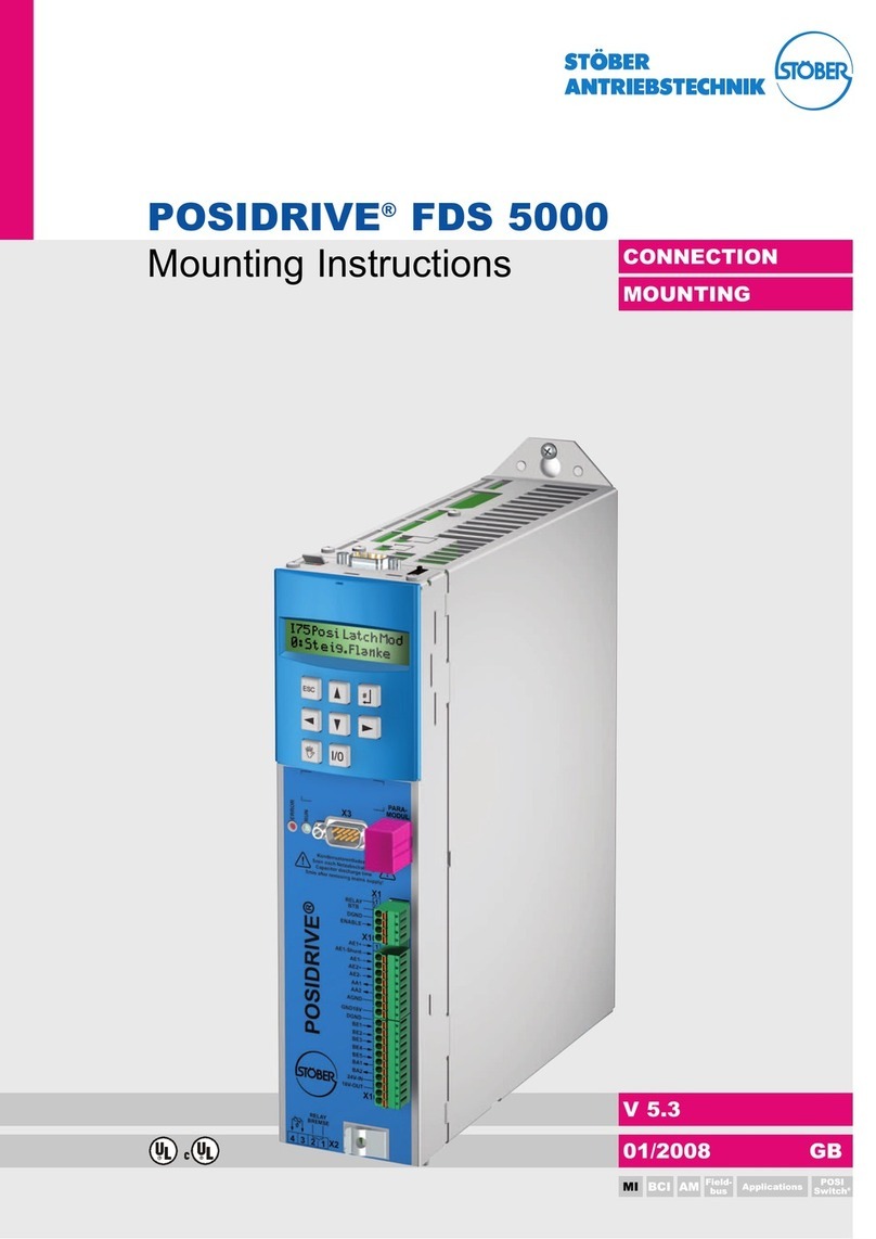
Stober POSIDRIVE FDS 5000 series User manual
Stober
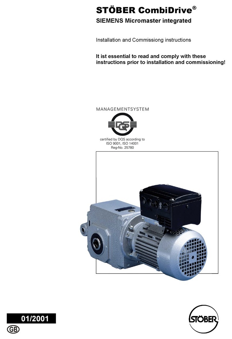
Stober Stober CombiDrive CM150/3 Installation and operation manual

Stober
Stober FDS 4000 Installation and operation manual
