Hafele Classic 80-B eDrive User manual

Slido Sliding Door Drive
Classic 80-B eDrive
Version: 1.0
Language: english
Original language: deutsch
Document: ------

2/26 Instruction Manual
Slido Classic 80-B eDrive-Version 1.10n
Imprint
Imprint
Häfele GmbH & Co KG
Adolf-Häfele-Str. 1
72202 Nagold
Germany
Tel: +49 (0)74 52 / 95 - 0
Fax: +49 (0)74 52 / 95 - 2 00
Dokumentinformationen
Dokumenttyp: Anschlussplan
Title: Slido Sliding Door Drive Classic 80-B eDrive
Version: 1.10
Sprache: English
Originalsprache: deutsch
Document: ------
Copyright notice
This is a copyrighted document. It is not allowed to copy it fully or partly, distribute it or use it without authority, if
the permission of the above mentioned originator is missing. All rights about the drawings and other documents
and the power of disposal is with the originator, also in the case of application for industrial property protection.
Declaration of conformity
This product fulfills the basic requirements of the applicable European Directives. The conformity was detected.
The original of the Declaration of conformity is available as a separate document from the manufacturer.
Technical subjects to change
Our products are always under further development and get improved. The data used for this document
represents the state of the product at the time of the creation of this document.
Changes of technical details are excepted. Please use the latest version of the document and contact the
manufacturer in case of doubt.
Questions
In case of questions contact the customer service. Please have the order number or serial number ready..

Slido Classic 80-B eDrive Version 1.0
Instruction Manual 3/26
Table of content
Table of content
1About this document..................................................................................................... 4
1.1.1 Target group ...................................................................................................................................... 4
1.1.2 Objective of this document ................................................................................................................ 4
1.1.3 Reference to other documents, guidelines and standards................................................................. 4
1.1.4 Used symbols .................................................................................................................................... 5
2Safety ............................................................................................................................. 6
2.1 Requirements for operation ..................................................................................................... 6
2.1.1 Environmental conditions................................................................................................................... 6
2.2 Proper use ............................................................................................................................... 6
2.3 Behavior in case of an error .................................................................................................... 6
3Functional description .................................................................................................. 7
3.1 General description ................................................................................................................. 7
3.2 Modes of operation.................................................................................................................. 8
4Cabling ........................................................................................................................... 9
4.1 Cable diagram ......................................................................................................................... 9
4.2 Cable requirements ................................................................................................................. 9
5Mounting and electrical connection............................................................................10
5.1 Mounting in a flush box.......................................................................................................... 10
5.2 Electrical connection.............................................................................................................. 11
5.2.1 Exemplary connection of on-site actuators ...................................................................................... 12
6Initial operaiton.............................................................................................................14
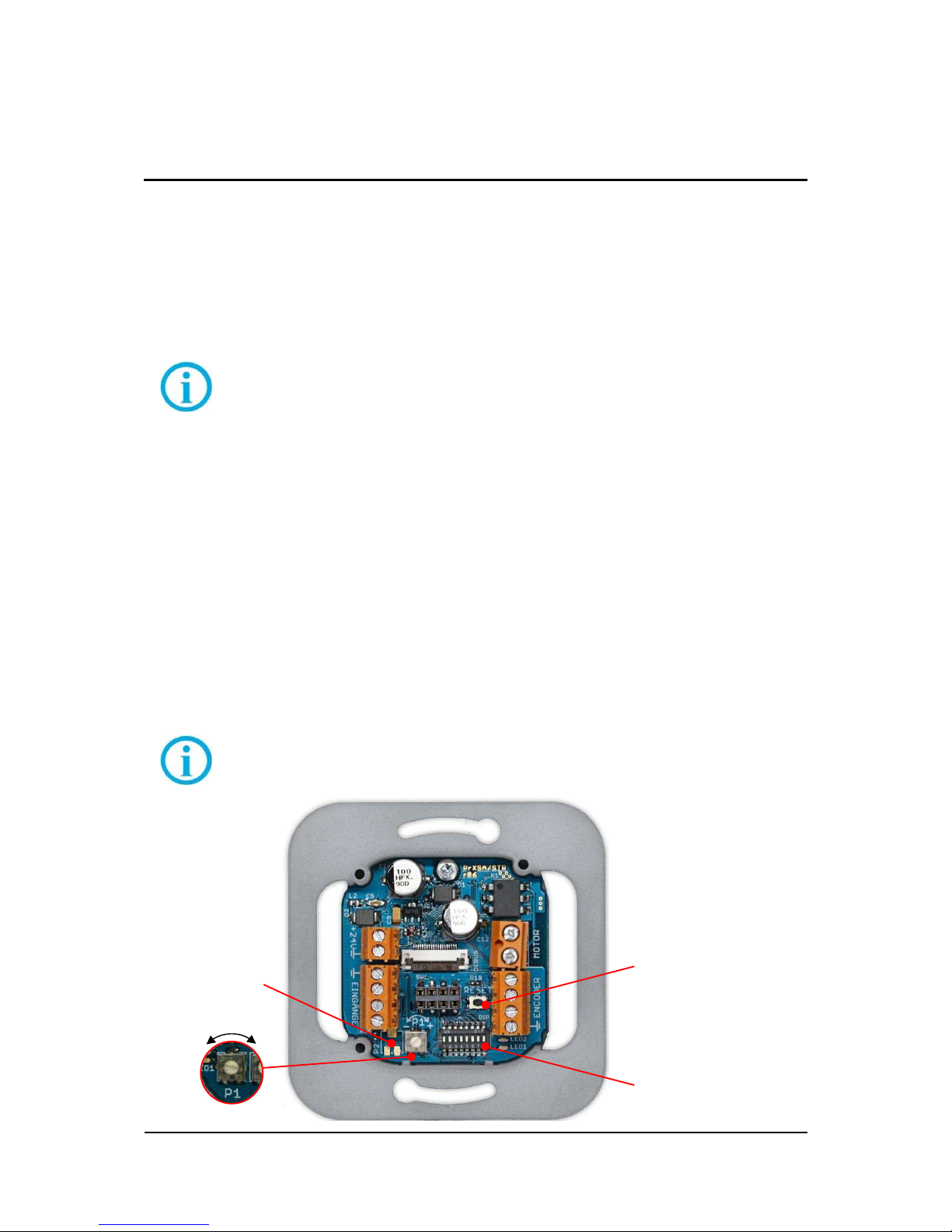
6.1 Configuration ......................................................................................................................... 14
6.1.1 Automatic closing delay time ........................................................................................................... 15
6.1.2 DIP switch........................................................................................................................................ 16
6.2 Steps during initial operation ................................................................................................. 18
6.3 Behavior after a power cut..................................................................................................... 19
6.4 Error mode............................................................................................................................. 20
7Wireless receiver ..........................................................................................................21
7.1 Mounting of wireless receiver ................................................................................................ 21
7.2 Programming of wireless receiver ......................................................................................... 21
7.2.1 Teach-in of hand transmitters .......................................................................................................... 22
7.2.2 Delete teached hand transmitters .................................................................................................... 22

4/26 Instruction Manual
Slido Classic 80-B eDrive-Version 1.10n
1
About this document
1 About this document
1.1.1 Target group
This document addresses qualified personnel only. The mounting must be done by technical educated, trained
and qualified personnel. Electrical wirings have to be done by a specialist.
This document has to be made accessible for qualified personnel. Its content must be read, understood and
followed.
1.1.2 Objective of this document
This document contains important information for mounting and wiring of the product. It has to be read before
working with the product. It must be handed out and explained to the operator and kept available all the time as a
part of the product.
1.1.3 Reference to other documents, guidelines and standards
Additional documents like guidelines, standards and laws for products of this kind, have to be considered.
Hint
The fabricator has an increased duty to advice the customer. The relevant guidelines, standards
and laws have to be considered.

Slido Classic 80-B eDrive Version 1.0
Instruction Manual 5/26
1
About this document
1.1.4 Used symbols
Hint
A hint gives important and additional information.
N O T I C E
Description of type and source of hazard
Warnings, marked with this symbol, are related to safety.
Disregard may result in property damage.
Steps to avoid hazards.
C A U T I O N
Description of type and source of hazards
This symbol indicates a hazardous situation which, if not
avoided, could result in minor or moderate injury and/or
property damage.
The following levels of warning show the severity and
probability of possible hazards, in ascending order.
CAUTION, colored yellow
WARNING, colored orange
DANGER, colored red
Steps to avoid hazards.
Lists
symbolizes a list with no specific order.
1. symbolizes a list or instruction in specific order.
Instructions
symbolizes an action.
symbolizes a reference.
symbolizes the result of an action.

6/26 Instruction Manual
Slido Classic 80-B eDrive-Version 1.10n
2
Safety
2 Safety
D A N G E R
Electric Shock
Danger to life and health due to electric shock.
Electrical connections have to be installed by approved
personnel only
Switch off power before carrying out work and secure
power against being switched on.
Observe relevant safety instructions.
2.1 Requirements for operation
Hint
Read the instruction manual before performing the initial operation
2.1.1 Environmental conditions
The 24 V motor control device for sliding doors is designed for standard wall jacks in dry interior.
2.2 Proper use
This product is a motor control device for the sliding door Slido Classic 80-B eDrive of the manufacturer. The
manufacturer’s specifications must be respected, in especially maximum and minimum dimensions and maximum
weight of the door leaf.
Any other use of this product is considered inappropriate use.
It is not guaranteed, that this product will work in combination with fittings, motors or other electronic devices of
other manufacturers.
2.3 Behavior in case of an error
In case of an error, the device must be shut down and the manufacturer must be informed.
Shut down
Do not operate device.
Disconnect device from power supply.
Inform the manufacturer.

Slido Classic 80-B eDrive Version 1.0
Instruction Manual 7/26
3
Functional description
3 Functional description
3.1 General description
The product Slido Classic 80-B eDrive is an electric drive for sliding doors. The motor control device Slido Classic
80-B eDrive /STR drives a 24V DC motor Slido Classic 80-B eDrive/MT. The motor drives a sliding door, to which
it is connected by a timing belt.
Hint
This document describes the functionality of the motor control device Slido Classic 80-B eDrive .
Instruction manuals for the installation of the mechanical part of the sliding door are available in
separate documents.
The control device is designed to fit in a standard flush box, according to DIN 49073. The control device
disappears into the flush box, including its electrical connections. For operation a removable switch is provided,
which fits into commercial available switch ranges with standard dimensions of 55mm.
The control device is powered by an external power supply unit. The PSU supplies 24V DC and is connected to
terminals 1 and 2. It can be placed in a flush box next to the control device. A distant mounting is also possible.
For information on the wiring, refer to chapter Fehler! Verweisquelle konnte nicht gefunden werden..
For electrical connections, screw terminals are provided. These are grouped by their function:
Power supply (Terminals 1 and 2), Control inputs (Terminals 1, 15, 21 and 29), Motor (Terminals MA and MB)
and Encoder (Terminals 1, 82, 85 and 86).
The encoder of the motor Slido Classic 80-B eDrive/MT has to be connected, to ensure proper operation.
The control device provides a potentiometer P1, to set the time the door stays open (automatic mode only). The
operation mode is selected by a DIP switch.
To perform the initial operation or to apply new settings, the reset key is used.
Hint
For further information on configuration and initial operation, refer to chapter Fehler!
Verweisquelle konnte nicht gefunden werden..
Potentiometer P1
Configuration Switch
LEDs for status
information
Reset key
-
+

8/26 Instruction Manual
Slido Classic 80-B eDrive-Version 1.10n
3
Functional description
Figure 1
Motor control device

Slido Classic 80-B eDrive Version 1.0
Instruction Manual 9/26
3
Functional description
3.2 Modes of operation
After installation and initial operation, the motor control device is ready to use.
The door drive starts to move, when the keys “open” or “close” of the switch cover are pressed, or when the
potential free inputs (Terminals 1, 21 and 29) are triggered.
The following modes of operation are possible:
Dead man’s control:
The drive moves in the desired direction, as long as the corresponding input signal is applied and no
obstruction is detected. Otherwise it stops instantly.
Semi-automatic mode:
The drive moves in the desired direction after a trigger impulse on the corresponding input signal. After an
opening command, it will stay open until a close command is applied.
When an obstruction is detected or a stop signal or a command contrary to the driving direction is applied,
the drive stops.
Automatic mode:
Additional to the semi-automatic behavior, the door closes automatically, when a close delay time is over.
When an obstruction is detected during closing, the drive reverses and remains open for the close delay time
again.
If a command contrary to the driving direction is given, the drive reverses. On a stop signal, the drive will
stop as long as the stop input is applied. After the stop signal is released, the drive continues its operation.
Temporarily remain opened:
In automatic mode it is possible to let the door remain in the open position.
To activate this feature it is necessary to press the “Open” and “Close” keys together for about two seconds.
After this, the door remains in the open position, until a close command is given. After closing, the drive
returns to automatic mode.

10/26 Instruction Manual
Slido Classic 80-B eDrive-Version 1.10n
4
Cabling
4 Cabling
4.1 Cable diagram
Usually the control device and the power supply are mounted in two neighboring flush boxes.
4.2 Cable requirements
The following specifications are minimum requirements.
For motor cabling a special cable is recommended, which fulfills the requirements. It is available from the
manufacturer.
Cable
Cable type
Between motor and control device.
Motor supply (24V =)
up to 20 m (60 ft): 2 x 0,50 mm² (20 AWG)
20 to 50 m (60..160 ft): 2 x 0,75 mm² (18 AWG)
Encoder
up to 50 m (160 ft): 4 x 0,25 mm² (22 AWG)
Between switch/actuator and control
device.
optional
up to 50 m (160 ft): 4 x 0,25 mm² (22 AWG)
Between power supply and control
device.
up to 20 m (60 ft): 2 x 0,50 mm² (20 AWG)
20 to 50 m (60..160 ft): 2 x 0,75 mm² (18 AWG)
Table 1 –Cable requirements
Power supply
3
Line
100..240 V~
50..60 Hz
Control device
2
24V =
Switch/Actuator
on-site
(optional)
4
Ground, Open,
Close, Stop
Motor
2
24V =
4
Encoder

Slido Classic 80-B eDrive Version 1.0
Instruction Manual 11/26
5
Mounting and electrical connection
5 Mounting and electrical connection
5.1 Mounting in a flush box
D A N G E R
Electric shock
Danger of dead, serious injury or property damage.
Cabling must be done by authorized and trained
personnel only.
Shut down main power before carrying out any work on
cabling.
Mounting of power supply unit (PSU) in a flush box
Put PSU in neighboring flush box.
Pay attention to requirements of PSU manufacturer.
Connect power line to PSU (brown and blue wires).
Bring leads for 24 V (red and black leads) into flush box for control device.
Power supply is mounted and ready for operation.
Mounting of control device and switch cover
Prepare cables of power supply and motor for connection.
Put control device in flush box.
Carry out electrical connections.
For details refer to chapter Fehler! Verweisquelle konnte nicht gefunden werden..
Secure control device with two screws.
Perform initial operation.
For details refer to chapter Fehler! Verweisquelle konnte nicht gefunden werden..
Place cover frame over control device.
Plug switch through cover frame into control device.
Control device and switch are mounted.
Figure 2 –Mounting of control device and switch
Cover frame
Switch
Control device
Flush box
(on site)

12/26 Instruction Manual
Slido Classic 80-B eDrive-Version 1.10n
5
Mounting and electrical connection
5.2 Electrical connection
C A U T I O N
Wrong installation
Damage of control device.
Observe polarity of connections.
Inputs (Terminals 1, 15, 21, 29) are potential free.
Carrying out electrical connections
Disconnect main power and protect against power up.
For safety instructions refer to chapter 2.
Connect power supply to terminals 1 and 2.
Terminal 2: 24V DC (+)
Terminal 1: Ground (-)
Connect motor to terminals MA and MB.
Polarity determines direction of operation.
Connect encoder.
Terminals 82, 86, 85 and 1
Connect on-site actuators (optional)
Terminals 1, 15, 21 and 29
Figure 3
Control device inputs
Motor
a
Motor 1
- blue
b
Motor 2
+ red
Encoder
1
Ground
white
85
Signal 1
yellow
86
Signal 2
green
82
+5V DC
brown
2
24V DC (+) power supply
1
Ground (-) power supply
On-site
control
inputs
29
Close
21
Open
15
Stop
1
Ground

Slido Classic 80-B eDrive Version 1.0
Instruction Manual 13/26
5
Mounting and electrical connection
5.2.1 Exemplary connection of on-site actuators
C A U T I O N
Wrong installation or initial operation.
Damage of control device or actuators.
Read documents of actuators manufacturer.
In case of questions contact manufacturer.
Motion detection example: Bircher Reglomat PrimeMotion C
Hint
Further information, especially mounting and initial operation of the motion detector, are available in
the instruction manual of the manufacturer.
Potential free
output signal
Power supply
PrimeMotion C
1
Ground
21
Open
yellow
green
24V DC (+)
Ground (-)
1
2
white
brown

14/26 Instruction Manual
Slido Classic 80-B eDrive-Version 1.10n
5
Mounting and electrical connection
Conventional open and close buttons (potential free, normally open).
Hint
Operation with one button is only possible in automatic operation mode (Open command).
Otherwise two buttons are necessary.
Button
Button
29
Close
1
Ground
21
Open

Slido Classic 80-B eDrive Version 1.0
Instruction Manual 15/26
6
Initial operation
6 Initial operation
After installation of the control device, an initial operation must be performed.
The following sections describe the parts of the control device, which are relevant for the initial operation. The
following chapters describe step by step, which functions must be set up and how the initial operation is done.
6.1 Configuration
The configuration is set via the potentiometer P1, the DIP switch and the reset button. The function of these
elements is described in the following sections.
Hint
Changes in configuration will take effect only when the control device changes into configuration
mode and leaves it again.
Set configuration before initial operation
Set desired parameters, while main power is off.
Perform initial operation.
For details refer to chapter Fehler! Verweisquelle konnte nicht gefunden werden.
Configuration is set during initial operation.

16/26 Instruction Manual
Slido Classic 80-B eDrive-Version 1.10n
6
Initial operation
6.1.1 Automatic closing delay time
The automatic closing delay time determines the time the door stays open in automatic operation mode. After the
delay time, the door closes automatically.
N O T I C E
Over tightened potentiometer
Damage of control device may result in malfunction.
Potentiometers have a right and a left stop, which must
not be over tightened.
Adjust potentiometer slightly and with an appropriate tool.
Prolong automatic closing delay time
Turn potentiometer P1 clockwise.
After configuration is applied, the door stays open for a longer time.
Refer to chapter 6.1
Reduce automatic closing delay time
Turn potentiometer P1 counter-clockwise.
After configuration is applied, the door stays open for a shorter time.
Refer to chapter 6.1
Hint
The minimum closing delay time is 5 seconds, the maximum closing delay time is 30 seconds.

Slido Classic 80-B eDrive Version 1.0
Instruction Manual 17/26
6
Initial operation
6.1.2 DIP switch
Switch
Description
OFF
(default)
ON
1
Operation mode
Semi-automatic
Automatic
2
Dead man’s control
Disabled
Enabled
3
Push & Go
Disabled
Enabled
4
Reaction on obstruction
Reverse
Stop
5
Closing speed
Reduced speed
Full speed
6
Safety stop
Disabled
Enabled
7 and 8
Setting of maximum speed
7
8
Door leaf/
Speed
OFF
OFF
Max. 80 kg
18 cm/s
ON
OFF
Max. 80 kg
20 cm/s
OFF
ON
Max 50 kg
25 cm/s
ON
ON
Max. 80 kg
15 cm/s
Table 2 - DIP switch
Switch 1 Operation mode semi-automatic / automatic:
When semi-automatic mode is set the drive will not close automatically. The potentiometer
P1 is without function.
When automatic mode is set the drive closes automatically.
Switch 2 Dead man’s control:
When dead man’s control is activated the drive will only operate, as long as an input signal
is applied. Switch 1 is inactive, when dead man’s control is selected.
Switch 3 Push & Go:
With push & go enabled the drive starts to move, as soon as the door leaf is pushed
manually.
Switch 4 Reaction on obstruction:
When reverse is set the drive stops and starts to move in the opposite direction, as soon as
an obstruction is detected. Otherwise it will stop until a new command is given. (This is only
possible in semi-automatic mode).
Switch 5 Closing speed:
By default the closing speed is slower than the opening speed. The closing speed can be
set as fast as the opening speed, by setting this switch to ON.
Switch 6 Safety stop:
When enabled, the drive will stop a short distance before its end position and will then close
with low speed. Otherwise it will stop directly in the end position.
ON
OFF

18/26 Instruction Manual
Slido Classic 80-B eDrive-Version 1.10n
6
Initial operation
Switch 7
Switch 8 The combination of switches 7 and 8 sets the maximum speed of the drive.
(Refer to table 2).
Maximum speed must be set according to the weight of the door leaf in order to fulfill the
safety specifications of DIN EN 18650.
Weight of door leaf up to 80 kg Maximum speed is 20 cm/s
Weight of door leaf up to 50 kg Maximum speed is 25 cm/s
Hint
The safety stop (which can be set with DIP switch No. 6) provides increased safety and is
recommended for use in sensitive areas like kindergartens or retirement homes.

Slido Classic 80-B eDrive Version 1.0
Instruction Manual 19/26
6
Initial operation
6.2 Steps during initial operation
W A R N I N G
Moving door leaf
Danger of injury by squashing, shearing or collision, caused
by moving door leaf.
Keep area clear during initial operation.
Prepare control device
Carry out electrical connections.
Refer to chapter 5.2
Set configuration.
Refer to chapter 6
Perform reset
Switch power supply on.
Control device in delivery status or after power cut:
Red LED blinks continuously twice with a short break of 1.5 sec.
Press RESET for about 2 seconds.
Red LED blinks continuosly.
Check driving direction of motor with control keys:
When pressing OPEN, door has to open and when pressing CLOSE, door has to close.
When driving direction is wrong:
Swap motor cables (terminals MA and MB), check driving direction again.
Move door in a middle position by pressing and holding the control keys.
Press RESET for about 2 seconds.
Red LED lights up permanently,
green LED lights up during motor activity.
Door moves in the open position,
door moves in the closed position,
door moves in the open position.
LEDs go out.
Check functionality
Test, if door shows desired behavior.
In case of malfunction check electrical connections and configuration.
For electrical connection refer to chapter 5.2
For configuration refer to chapter 6.1
Repeat initial operation, if necessary.
Initial operation is completed, when function is correct.
…
…
…

20/26 Instruction Manual
Slido Classic 80-B eDrive-Version 1.10n
6
Initial operation
6.3 Behavior after a power cut
When the main power is cut off, the control device will not work. The control device can be operated without an
initial operation, when main power is restored (Provided that the control device has already been put into
operation).
Bring control device back into normal operation
Restore main power.
Control device after power cut:
Red LED blinks continuously twice with a short break of 1.5 sec.
Execute desired action:
Press OPEN to open the door, press CLOSE to close the door.
First movement will start with reduced speed.
Normal operation is restored.
Hint
After a power cut, no further initial operation is necessary. The operation parameters are saved
permanently during initial operation.
…
Table of contents
Other Hafele DC Drive manuals