Stober POSIDRIVE FDS 5000 series User manual

POSIDRIVE®FDS 5000
Mounting Instructions CONNECTION
MOUNTING
V 5.3
01/2008 GB
MI AM
BCI Field-
bus Applications POSI
Switch®

POSIDRIVE®FDS 5000 - Mounting Instructions
STÖBER
ANTRIEBSTECHNIK
Table of Contents
TABLE OF CONTENTS
1. Notes on Safety 1
1.1 Hardware 2
1.2 Software 3
2. Technical Data 4
2.1 Electrical 4
2.2 Mechanical 7
3. Mechanical Installation 8
3.1 Installation location 8
3.2 Mounting/mounting dimensions 8
3.2.1 Without bottom 8
3.2.2 With bottom brake resistor 9
3.3 Installation of accessories 9
3.3.1 Option module 1 (fieldbus, terminals) 9
3.3.1.1 CANopen DS-301 (CAN5000) /
PROFIBUS DP-V1 (DP5000) 9
3.3.1.2 EtherCAT (ECS5000) 10
3.3.1.3 I/O terminal module (LEA5000) 10
4. Electrical Installation 11
4.1 EMC 11
4.2 RCD circuit breaker 11
4.3 Power connection 11
4.4 DC link coupling 12
4.4.1 Basic Circuit Diagram 12
4.4.2 Combinations 13
4.4.3 Fuses 13
4.5 Safety function „safe torque off“ 14
4.5.1 Description 14
4.5.2 Use 14
4.5.3 Function test 17
4.5.4 Remaining dangers 17
4.6 Motor cable fabrication 18
4.7 Installation after storage period 18
5. Connection allocation 19
5.1 Terminal overview 19
5.3 Terminal allocation (X1 – X302) 20ff
6. Examples of connections 31
6.1 General 31
6.1.1 Brake connection with BRM 5000 for
24 V DC brakes (Imax=2 A, Pmax=48 W) 31
6.1.2 Brake connection with interface relay 32
6.1.3 Brake connection with powerbox 33
6.2 Terminals 34
6.2.1 Example 1 34
6.2.2 Example 2 34
7. Accessories 35
7.1 Accessory overview 35
7.2 Brake resistor 37
7.2.1 FZM(U) and VHPR 37
7.2.2 Bottom brake resistor RB 5000 38
7.3 Output deraters 39

5th Generation of STÖBER Inverters
STÖBER
ANTRIEBSTECHNIK
1. Notes on Safety
1
1NOTES ON SAFETY
This manual contains information which must be adhered to in order to prevent personal
injury and property damage. This information is graduated by degree of damage as
shown below.
ATTENTION
Means that an undesired result or undesired state may occur if this note is not heeded.
CAUTION
Without warning triangle: Means that property damage may occur if appropriate
precautions are not taken.
CAUTION
With warning triangle: Means that minor personal injury and property damage may occur
if appropriate precautions are not taken.
WARNING
Means that major danger of death and substantial property damage may occur if
appropriate precautions are not taken.
DANGER
Means that great danger to life and substantial property damage will occur if appropriate
precautions are not taken.
NOTE
Indicates an important piece of information on the product or the drawing of attention to a
part of the documentation requiring special attention.
ACTION
Means the description of an action which is particularly important for handling the
product.
5th Generation of STÖBER Inverters
STÖBER
ANTRIEBSTECHNIK
1. Notes on Safety
2
1.1 Hardware
WARNING
To ensure that avoidable problems do not occur during commissioning and/or operation,
be sure to read these installation and commissioning instructions before installation and
commissioning.
In the sense of DIN EN 50178 (formerly VDE 0160), the FDS and MDS model series of
POSIDRIVE®are electrical components of power electronics for the regulation of energy
flow in high-voltage systems. They are exclusively designed to power servo (MDS) and
asynchronous (FDS, MDS) machines. Utilization, installation, operation and maintenance
are only permitted under observation and adherence to valid regulations and/or legal
requirements, applicable standards and this technical documentation.
This is a product of the restricted sales class in accordance with IEC 61800-3. In a
residential zone, this product may cause high-frequency interference in which case the
user may be requested to take suitable measures.
Strict adherence to all rules and regulations must be ensured by the user.
The safety notes contained in further sections (items) and specifications must be
adhered to by the user.
WARNING
Caution! High touch voltage! Danger of shock! Danger to life!
When network voltage is applied, never under any circumstances open the housing or
disconnect the connections. When installing or removing option boards, you may only
open the inverter in the dead state (all power plugs disconnected) and only after a
waiting period of at least 5 minutes after the network voltage is switched off. Prerequisite
for the correct functioning of the inverter is the correct configuration and installation of
the inverter drive. Transport, installation, commissioning and handling of the device may
only be performed by qualified personnel who have been especially trained for these
tasks.
Pay particular attention to the following:
•Permissible protection class: Protective ground. Operation is only permitted when the
protective conductor is connected in accordance with regulations. Direct operation of
the devices on IT networks is not possible.
•Installation work may only be performed in the dead state. For work on the drive, lock
enable and disconnect the complete drive from the power. (Observe the 5 safety
rules.)
•Leave the plug for the DC link coupling connected even when the DC link coupling is
not being used (BG0-BG2: X22)!
•Discharge time of the DC link capacitors > 5 minutes.
•Do not penetrate the device's interior with any kind of object.
•During installation or any other work in the switching cabinet, protect the device
against falling parts (pieces of wire, stranded wire, pieces of metal, and so on). Parts
with conductive properties may cause a short circuit within the inverter or device
failure.
•Before commissioning, remove extra coverings so that the device cannot overheat.
The inverter must be installed in a switching cabinet in which the maximum ambient
temperature (see technical data) is not exceeded. Only copper lines may be used. The
line cross sections to be used are contained in table 310-16 of the NEC standard at
60 oC or 75 oC.
The company STÖBER ANTRIEBSTECHNIK GmbH + Co. KG accepts no liability for
damages resulting from non-adherence to the instructions or the particular
regulations.

5th Generation of STÖBER Inverters
STÖBER
ANTRIEBSTECHNIK
1. Notes on Safety
3
The motor must have an integral temperature monitor with basis insulation as per
EN 61800-5-1 or external motor overload protection must be used.
Only suitable for use on supply current networks which cannot deliver more than a
maximum symmetric, nominal, short-circuit current of 5000 A at 480 Volt.
Integral solid state short circuit protection does not provide branch circuit protection.
Branch circuit protection must be provided in accordance with the Manufacturer
Instructions, National Electrical Code and any additional local codes”, or the equivalent.
Subject to technical changes without prior notification which changes serve to
improve the devices. This documentation is purely a product description. It does
not represent promised properties in the sense of warranty law.
1.2 Software
Use of the POSITool software
The POSITool software package can be used to select an application, adjust parameters
and signal monitoring of the 5th generation of STÖBER inverters. The functionality is
specified by the selection of an application and the transmission of these data to an
inverter.
The program is the property of STÖBER ANTRIEBSTECHNIK GmbH + Co. KG and is
protected by copyright. The program is licensed for the user.
The software is provided exclusively in machine-readable format.
The customer receives from STÖBER ANTRIEBSTECHNIK GmbH + Co. KG a non-
exclusive right to use the program (license) if the program was obtained legally.
The customer has the right to utilize the program for the above stated activities and
functions and to make and install copies of the program, including one backup copy, for
support of said utilization.
The conditions of this license apply to all copies. The customer is obligated to place the
copyright note and all other ownership notes on every copy of the program.
The customer is not authorized to use, copy, change or pass on/transmit the program for
reasons other than those covered by these conditions; the customer is also not
authorized to convert the program (reverse assembly, reverse compilation) or compile
the program in any other manner, or to sublicense, rent or lease the program.
Product maintenance
The obligation to perform maintenance applies to the two last current program versions
prepared and released for use by STÖBER ANTRIEBSTECHNIK GmbH + Co. KG.
STÖBER ANTRIEBSTECHNIK GmbH + Co. KG can either correct program errors or
provide a new program version. The choice is up to STÖBER ANTRIEBSTECHNIK
GmbH + Co. KG. If, in individual cases, the error cannot be corrected immediately,
STÖBER ANTRIEBSTECHNIK GmbH + Co. KG will provide an intermediate solution
which, if necessary, requires adherence by the user to special operating regulations.
The claim to error correction only exists when reported errors are reproducible or can be
recorded by machine-made outputs. Errors must be reported in reconstructable form
giving useful information for error correction.
The obligation to correct errors is invalidated for such programs which the customer
changes or manipulates unless the customer can prove when reporting the error that the
manipulation is not the cause of the error.
STÖBER ANTRIEBSTECHNIK GmbH + Co. KG is obligated to keep the currently valid
program versions in a specially protected place (fire-resistant data safe, safety deposit
box at a bank).

POSIDRIVE®FDS 5000 – Mounting Instructions
STÖBER
ANTRIEBSTECHNIK
2. Technical Data
4
2TECHNICAL DATA
Model key
FDS 5075/H
2.1 Electrical
General (for all sizes)
Output voltage 3 x 0 V up to connection voltage
Output frequency 0 – 400 Hz
Radio interference suppression EN 61800-3, interference emission, class C3
International certifications ---
Storage/transportation temperature -20 °C to +70 °C, max. of change: 20 K / h
Max. surrounding air temperature 0 to 45 °C with rated data,
up to 55 °C with power reduction of 2.5% / °C
Relative humidity during operation Relative humidity 85%, no condensation
Altitude of installation Up to 1000 m above sea level without restriction
1000 to 2000 m above sea level with power reduction of 1.5% / 100 m
High voltage category III in accordance with EN 61800-5-1
Degree of soil Degree of soil 2 in accordance with EN 60204 / EN 50178
Protection rating IP 20
Installation position Generally vertical
Ventilation Built in fan
5th generation
Powe
r
075 = 7.5 kW
A
uxiliary voltage, control electronics
/H ... High level, DC link
/L ... Low level, 24 V external (in preparation)
Designation

POSIDRIVE®FDS 5000 – Mounting Instructions
STÖBER
ANTRIEBSTECHNIK
2. Technical Data
5
Size 0 / BG 0
Device Type FDS 5007 FDS 5004 FDS 5008 FDS 5015
ID no. 45962 45961 45963 45964
Recommended motor
power 0.75 kW 0.37 kW 0.75 kW 1.5 kW
Connection voltage (L1-N) 1 x 230 V
+20%/-40%,50/60Hz
(L1-L3) 3 x 400 V +32%/-50% 50 Hz
(L1-L3) 3 x 480 V +10%/-58% 60 Hz
Power fuses11 x 10 AT 3 x 6 AT 3 x 6 AT 3 x 10 AT
Operation with three-phase current motor (control mode V/f, VC, SLVC)
Rated current IN3 x 4.0 A 3 x 1.3 A 3 x 2.1 A 3 x 4.0 A
Imax 180% / 5 sec., 150% / 30 sec.
Clock pulse frequency 4 kHz (adjustable up to 16 kHz with derating)
Brake resistor
(accessories),
cf. chap. 7.2
100 Ω: Max. of
1.6 kW 200 Ω: Max. of 3.2 kW
Perm. motor cable
length, shielded
50 m
Output derating is required for distances of 50 m to 100 m (see chapter 7.2.3).
Power loss at Ia = IN80 W 50 W 65 W 90 W
Power loss at Ia = 0A2Max. of 30 W2
Conductor cross
section Max. of 2.5 mm2
Dimensions (H x B x T)
[mm] 300 x 70 x 157 (175)3
without
packaging 2.1
Weight
[kg] with
packaging 2.9
Upper voltage limit 440 V 830 V
Brake chopper on level 400 V / 420 V 780 V / 800 V
Brake chopper disable
voltage 360 V / 380 V 740 V / 760 V
1Line circuit breaker, tripping characteristic C, EN 60 898
Use class RK1 fuses for UL adherence: Class RK1 (e.g., Bussmann KTS-R-xxA / 600 V)
2Depends on the option boards and sensors connected (e.g., encoder)
3Depth including braking resistor RB 5000

POSIDRIVE®FDS 5000 – Mounting Instructions
STÖBER
ANTRIEBSTECHNIK
2. Technical Data
6
Size 1 / BG 1
Device Type FDS 5022 FDS 5040 FDS 5055 FDS 5075
ID no. 45965 45966 45967 45968
Recommended
motor capacity 2.2 kW 4.0 kW 5.5 kW 7.5 kW
Connection voltage (L1-L3) 3 x 400 V +32%/-50% 50 Hz
(L1-L3) 3 x 480 V +10%/-58% 60 Hz
Power fuses13 x 10 AT 3 x 16 AT 3 x 20 AT 3 x 20 AT
Operation with three-phase current motor (control mode V/f, VC, SLVC)
Rated current IN3 x 5.5 A 3 x 10 A 3 x 12 A 3 x 16 A
Imax 180% / 5 sec., 150% / 30 sec.
Clock pulse frequency 4 kHz (adjustable up to 16 kHz with derating)
Brake resistor
(accessories),
cf. chap. 7.2
100 Ω: Max. of 6.4 kW 47 Ω: Max. of 13.6 kW
Perm. motor cable
length, shielded
50 m
Output derating is required for distances of 50 m to 100 m (see chapter 7.2.3).
Power loss
at Ia = IN110 W 170 W 180 W 200 W
Power loss
at Ia = 0A2Max. of 30 W2
Conductor cross
section Max. of 4 mm2
Dimensions (H x B x T)
[mm] 300 x 70 x 242 (260)3
without
packaging 3.7
Weight
[kg] with
packaging 4.8
Upper voltage limit 830 V
Brake chopper on level 780 V / 800 V
Brake chopper disable
voltage 740 V / 760 V
1Line circuit breaker, tripping characteristic C, EN 60 898
Use class RK1 fuses for UL adherence: Class RK1 (e.g., Bussmann KTS-R-xxA / 600 V)
2Depends on the option boards and sensors connected (e.g., encoder)
3Depth including braking resistor RB 5000
POSIDRIVE®FDS 5000 – Mounting Instructions
STÖBER
ANTRIEBSTECHNIK
2. Technical Data
7
2.2 Mechanical
Dimensions in mm BG 0 BG 1
Height h 300
Height
(incl. EMC shield plate) hb 360
Width w 70
d1 157 242
EMC shield plate
Base plate
mounting holes
Weight [kg]
Depth d2* 175 260
Height e 37.5
EMC shield plate Depth f 40
Distance a 283
Mounting holes Vertical position
on the base plate b 6
Without packaging 2.1 3.7
Weight [kg] With packaging 2.9 4.8
* d2 = Depth incl. brake resistor RB 5000
POSIDRIVE®FDS 5000 – Mounting Instructions
STÖBER
ANTRIEBSTECHNIK
3. Mechanical Installation
8
3MECHANICAL INSTALLATION
This chapter gives you complete information on the subject of mechanical installation.
Only specialized personnel who are qualified for this task may install, commission and operate the device.
3.1 Installation Location
•Operate only in closed switching cabinet (adhere to protection rating IP 20).
•Install inverter only in vertical position.
•Avoid installation above heat-generating devices.
•Ensure sufficient air circulation in the switching cabinet
(Adhere to minimum free spaces as per table in chap. 3.2.).
•Installation site free of dust, corrosive fumes and all liquids
(in accordance with soiling degree 2 in accordance with EN 60204 / EN 50178)
•Avoid atmospheric humidity.
•Avoid condensation (e.g., due to anti-condensation heating elements).
•To meet EMC requirements, use mounting plates with conductive surface (e.g., unpainted).
3.2 Mounting/Mounting Dimensions
3.2.1 Without Bottom
Drilling jig Free space
283
A
B
C
C
Min. Free
Space
[Dimensions
in mm]
A
Up
B
Down
C
To Right
/ Left
Screws
Without EMC
shielding plate 100 100 5 M5
With EMC
shielding plate 100 120 5 M5

POSIDRIVE®FDS 5000 – Mounting Instructions
STÖBER
ANTRIEBSTECHNIK
3. Mechanical Installation
9
D
A
C
B
B
3.2.2 With Bottom Brake Resistor
The "brake resistor RB 5000" substructure is the ideal solution when space is
limited. It is placed between mounting surface and MDS 5000. This increases
the mounting depth by approx. 20 mm.
Mounting
•Secure the bottom brake resistor (A) on the mounting surface
with the included threaded bolts and spring rings (same drilling
diagram as MDS 5000) (B).
•Hook the MDS 5000 in on the four guides (C).
•Secure the MDS 5000 to the threaded bolts with the two
included screws (D).
3.3 Installation of Accessories
Only specialized personnel who are qualified for this task may install accessories (cf. chap. 7). Suitable measures must be
provided against damage by electrostatic discharging (in accordance with DIN EN 50082-2). Before installation, the device must
be disconnected from the power and, with the device version FDS 5xxx/L, the 24 V power must be turned off.
CAUTION
Immediately after the power is turned off, the DC link is still charged. Wait > 5 min. for the DC link to discharge
after turning off the power voltage. To prevent damage to device and accessory parts, install the accessory
afterwards.
CAUTION
Danger of electrostatic charges damaging the PCB!
Perform potential equalization before you touch a PCB (option module 1).
3.3.1 Option module 1 (fieldbus, terminals)
3.3.1.1 CANopen DS-301 (CAN5000) / PROFIBUS DP-V1 (DP5000)
Installation is the same for both modules.
•Make sure that the device is without power. Wait ≥5 min. for the DC link capacitors to discharge after turning off the power
supply voltage.
•Disconnect the cover plate by removing the two screws (E).
•Remove the prepunched area (A) for the sub D plug connector on the plate.
•Mount the plate on the board with the included UNC bolts (B).
•Slide the fieldbus board (C) with the gold-contacted terminal surfaces (D) into the black terminal block.
CAUTION
Be sure not to touch the gold contact surface with your fingers (danger of fouling and corrosion).
•Check correct position of the board.
•Secure the board with the two included screws (E).
•Then apply included labels (nameplate and adhesive label for switch setting (CAN)) to the cover plate.
A
D
BCAN5000
DP5000
C
E

POSIDRIVE®FDS 5000 – Mounting Instructions
STÖBER
ANTRIEBSTECHNIK
3. Mechanical Installation
10
3.3.1.2 EtherCAT (ECS5000)
•Make sure that the device is without power. Wait ≥5 min. for the DC link capacitors to discharge after turning off the power
supply voltage.
•Disconnect the cover plate by removing the two screws (C).
•Slide the EtherCAT board (A) with the gold-contacted terminal surfaces (B) into the black terminal block.
CAUTION
Be sure not to touch the gold contact surface with your fingers (danger of fouling and corrosion).
•Check correct position of the board.
•Secure the board with the two included screws (C).
•Then apply included labels (nameplate) to the cover plate.
3.3.1.3 I/O terminal module (LEA5000)
•Make sure that the device is without power. Wait ≥5 min. for the DC link capacitors to discharge after turning off the power
supply voltage.
•Disconnect the cover plate by removing the two screws (C).
•Slide the board (A) with the gold-contacted terminal surfaces (B) into the black terminal block.
CAUTION
Be sure not to touch the gold contact surface with your fingers (danger of fouling and corrosion).
•Check correct position of the board.
•Secure the board with the two included screws (C).
•Then apply included labels (nameplate) to the cover plate.
LE
A
5000
A
C
B
ECS5000
C
A
B

POSIDRIVE®FDS 5000 – Mounting Instructions
STÖBER
ANTRIEBSTECHNIK
4. Electrical Installation
11
4ELECTRICAL INSTALLATION
This chapter gives you complete information on the subject of electrical installation.
Only specialized personnel who are qualified for this task may install, commission and control the device.
4.1 EMC
This chapter contains general information on EMC-suitable installation. These are only recommendations. Depending on the
application, the ambient conditions and the legal requirements, measures in addition to the following recommendations may be
required.
•Mount device or Bottom Brake Resistor on conductive surface (unpainted).
•Install the power cables in spatially separately from the signal lines (encoder, analog/digital signal lines).
•Use only shielded cable for motor lines (corresponding cabels can be ordered from STÖBER ANTRIEBSTECHNIK.).
•Apply shield of the motor cable over a large surface in the immediate vicinity of the FDS 5000. The EMC shield plate
(EM 5000) for mounting on the bottom of the device is available as an accessory (see chap. 3.2.3 and chap. 7.1).
•With asynchronous machines, apply the shield to the terminal block over a large surface (e.g. PG shield screw connection).
•Use output deraters for motor lines > 50 m.
•When an additional transfer plug connector is to be installed in the motor cable, the cable shield may not be interrupted.
•When the brake line is installed in the motor cable, the brake line must be shielded separately.
•When the length of the cable for connection of a brake resistor is longer than 30 cm, this must be shielded and the shield
must be applied over a large surface in the immediate vicinity of the FDS 5000.
•Connect the shield of the control lines on one side with reference ground of the reference value source (e.g., PLC or CNC).
•Shield, and, if necessary, twist reference value lines before installing.
4.2 RCD (Residual Current Protective Devices)
Network phases and neutral conductors are connected with the protective conductor via Y capacitors. When network voltage is
applied, a leakage current flows over these capacitors to the protective conductor. The greatest leakage current occurs during a
malfunction (asymmetric feedin via only one phase) and during power-on (sudden change in voltage). The maximum leakage
current due to asymmetric power feedin is 40 mA (network voltage of 400 V) for FDS inverters.
If RCD circuit breakers are necessary, the problem of power-on and off can be alleviated by using selective RCD circuit
breakers (switch-off delay) or RCD circuit breakers with increased tripping current (e.g., 300 or 500 mA). Only all-current
sensitive RCD circuit breakers may be used. Operation of several devices on one RCD circuit breaker is not recommended.
4.3 Power Connection
Protection via line circuit breakers in accordance with the values listed in chap. 2 (tripping characteristic C, in accordance with
EN 60 898) or suitable, delayed safety fuse.
Use class RK1 fuses for UL conformance: Class RK1 (e.g., Bussmann KTS-R-xxA / 600 V)

POSIDRIVE®FDS 5000 – Mounting Instructions
STÖBER
ANTRIEBSTECHNIK
4. Electrical Installation
12
4.4 DC Link Coupling
If you are using axes in a plant which operate in a network of generators and motors, the DC link coupling (DC coupling) can be
advantageous. When the DC-coupling is used, the excess energy of other axes is made available as drive power instead of
converting this excess power into heat with a brake resistor. Remember that you will need a brake resistor which can absorb the
power peaks when all drives in the DC-link network brake at the same time.
DANGER
Danger of damage to devices! When single-phase and three-phase devices are coupled,
the single-phase devices will be destroyed. Use only three-phase devices for the DC link
coupling!
CAUTION
Danger of damage to devices! When one device within the DC-link coupling network fails,
the complete DC-link coupling network must be disconnected from the power network since
other devices in the DC-link coupling network may be damaged. Be sure to adhere to the
wiring of the ready-for-operation relay shown in chapter 4.5.1 (X1.1 and X1.2). When a
failure occurs, replace all devices of one group.
NOTE
Please note that the parameter A38 DC power-input must be set before the DC link
coupling will function correctly.
Group 1: A38 = 0: inactive
Group 2 and 3: A38 = 1: active
For more details, also see the description of the parameter.
4.4.1 Basic Circuit Diagram
The following diagram shows the basic circuiting of the DC-link coupling. The inverters can be coupled together in up to three
groups. The table in chapter 4.5.2 shows the possible combinations. The combination determines the types of power fuse and
DC-link fuse.
MDS/FDS
5000
MDS/FDS
5000
MDS/FDS
5000
MDS/FDS
5000
MDS/FDS
5000
MDS/FDS
5000
MDS/FDS
5000
X10 X10 X10 X10X10 X10 X10
X1 X1 X1 X1X1 X1 X1
X22
1
X22
1
X22 X22X22
1
X22 X22
U+
RB RB U+ U+ U+U+ U+ U+U- U- U- U-U- U- U-
11111112222222
L1
L2
L3
PE
BTB
2
Figure 4-1 Basic circuit diagram for the DC link coupling
1For MDS 5000 devices of size BG3: X20, terminals DC-link +, DC-link -
2Dimension the brake resistor to fit the braking power of the DC-link network and the technical data of the device.
G
r
oup 1
G
r
oup 2
Powe
r
fuse
G
r
oup 3
DC-link fuse DC-link fuse
Floating signal
contact - must be
integrated in the
safety circuit of the
controller.
Braking
resistor

POSIDRIVE®FDS 5000 – Mounting Instructions
STÖBER
ANTRIEBSTECHNIK
4. Electrical Installation
13
4.4.2 Combinations
The following table shows the possible combinations for the DC-link coupling. A total of 15 combinations are available.
Example: Combination no. 7
This combination lets you combine one size-1 inverter in group 1 with two size-0 devices in group 2. There is no group 3. The
power fuse must have a nominal current of 20 A. The groups are separated from each other with the type-1 DC-link fuse (see
chapter 4.4.3). Wait three minutes before turning on the devices of the DC-link coupling again.
Group 1 DC-Link
Fuse Group 2 DC-Link
Fuse Group 3 Switchon Wait
Time [min]
Type MDS/FDS 5000 MDS 5000 MDS/FDS 5000 MDS/FDS
Size BG0 BG1 BG2 BG3 BG0 BG1 BG0
Power fuse110 A 20 A 50 A 80 A – – –
Max. P-IN 4 kW 10 kW 20 kW 45 kW – – –
Combinationno.
1 max. 4 – – 1
2 max. 4 – – 5
3 3 Type 1 2 – 5
4 3 Type 1 1 – 3
5 2 Type 1 2 – 3
6 2 Type 1 1 – 4
7 1 Type 1 2 – 3
8 max.3 – – 2
9 3 Type 2 1 Typ 1 2 2
10 3 Type 1 2 – 2
11 3 Type 2 1 – 2
12 2 Type 2 1 – 2
13 2 Type 2 1 Typ 1 1 2
14 1 Type 1 1 – 2
15 max. 3 – 1
Instead of delaying the process by the switchon wait time, you can determine the switchon point in time by evaluating parameter
E14. The parameter must indicate in all-network connected devices that the charging relays are open before the voltage can be
switched through again. You can query the parameter via fieldbus or binary output.
4.4.3 Fuses
CAUTION
Danger of machine standstill! When one fuse element fails, the second fuse element is
damaged. Always replace the elements of a fuse in pairs.
Use the following fuses to protect the DC-link coupling:
Type 1 Type 2
Manufacturer SIBA Sicherungs-Bau GmbH
Borker Straße 22
D-44534 Lünen
www.siba.de
Size 10 x 38
Rated voltage AC 500 V
Rated current 10 A 20 A
Power loss per element 1.6 W 3,5 W
Art. no. of fuse 60 034 34.10 60 034 34.20
Art. no. of fuse holder 51 063 04.3
1For use conforming to UL, see specifications in the technical data.
Keep the following points in mind during installation
and operation:
•Use shielding for DC-link coupling connections
longer than 20 cm. This will prevent EMC problems.
•Use the two outer elements of the fuse holder.
POSIDRIVE®FDS 5000 – Mounting Instructions
STÖBER
ANTRIEBSTECHNIK
4. Electrical Installation
14
4.5 Safety function „safe torque off“
NOTE
The certified version of the safety function is not available with the FDS 5000.
NOTE
The ASP 5001 may only be installed and repaired by STÖBER ANTRIEBSTECHNIK.
NOTE
When certified use is required, the inverter must be installed in a switching cabinet with a
protection rating of IP54.
4.5.1 Description
On the MDS 5000 inverter the safety function "safe torque off" can be implemented with option ASP 5001. When the safety
function is used the inverter must be able to be switched off in two different ways. The first way to switch off the inverter uses
the enable function. Diagnosis is performed via a binary output or a fieldbus system.
The second way to switch off the inverter uses the ASP 5001 option in addition. When the ASP 5001 option is activated, control
of the end stage is switched off with the positively-driven switch elements of a safety relay. The reference value input is
disabled, and the signal contact is switched to an external safety circuit (break contact). The motor cannot start up even when
there are defects in the end stage or the control circuit since the necessary phase sequence is no longer generated.
Advantages of the ASP 5001 option:
•No switching of the network voltage necessary and the DC link remains charged. This permits a faster restart.
•Less contact wear since only low voltage is switched.
•Less additional wiring work.
4.5.2 Use
WARNING
The starting lockout option only switches off the end stage. Dangerous voltages may still be
present on the motor terminals!
This means that the starting lockout option does not provide galvanic isolation from the
power network. The function does not provide protection against "electrical shock."
During maintenance or repair work an appropriate voltage-free circuit and system protection
are required.
The regulations for emergency off situations must be adhered to.
WARNING
Since the safety function ensures that the motor torque is switched off, axes that are moving
vertically must be protected against crashing down.
WARNING
Since the motor may run down in an undefined state when the starting lockout is activated
during operation, it is essential to adhere to the switchoff sequences which will be described
in the following section (1st and 2nd ways to switch off).
POSIDRIVE®FDS 5000 – Mounting Instructions
STÖBER
ANTRIEBSTECHNIK
4. Electrical Installation
15
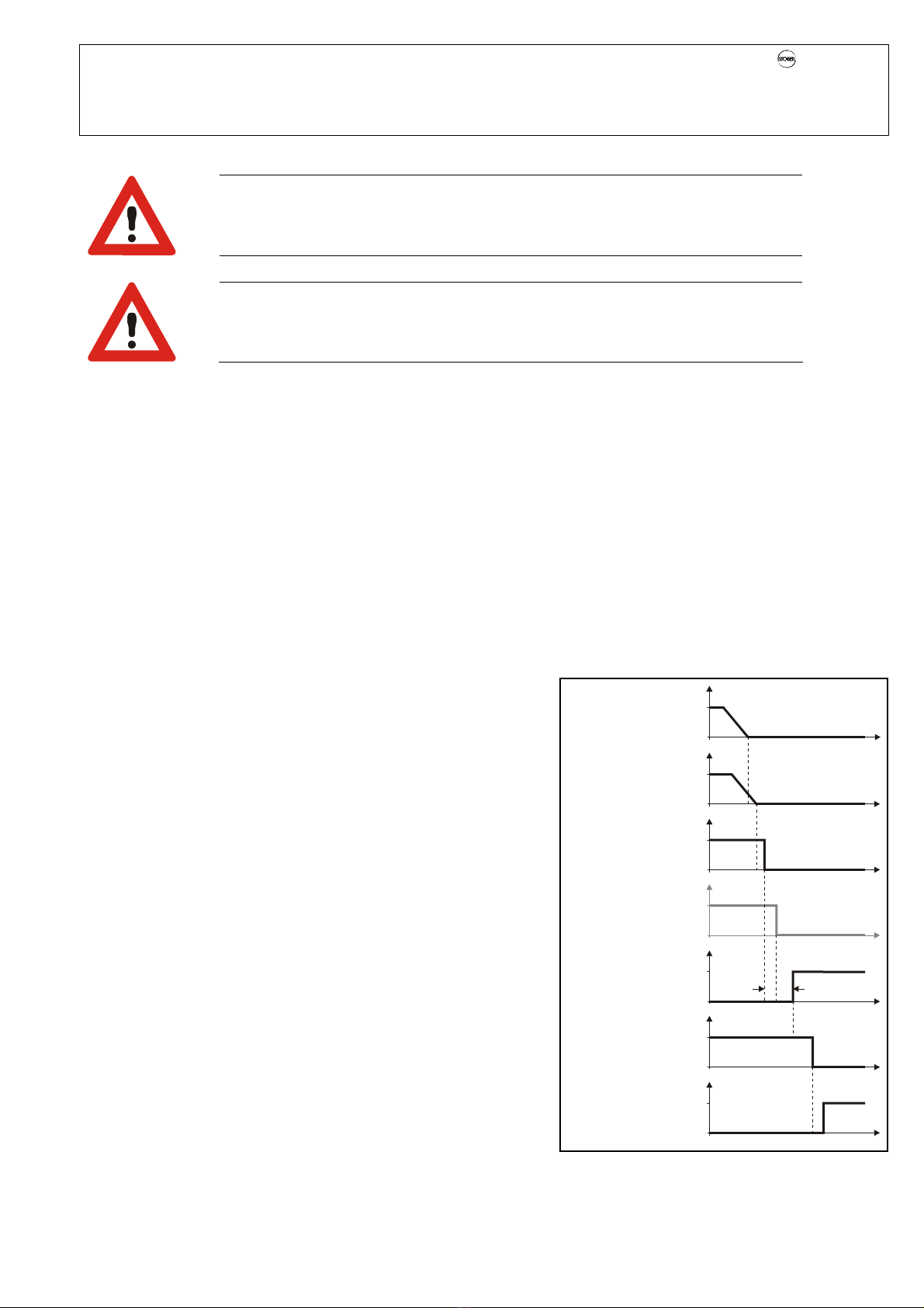
Figure 4-2 Timing diagram
1st way to switch off: Enable
WARNING
1.Switchoff distance may not take effect. If you deviate from a standard configuration, you
must ensure that the 1st switchoff distance (i.e., the enable) always takes effect.
WARNING
1. Switchoff distance did not take effect. Set A55 = 0:inactive since the 1st switchoff distance
can be made ineffective by the operator panel if you allow local mode (A55 = 1:active).
The power end stage is activated on the inverter by applying a 24 V signal to terminals X1.3 and X1.4.
The following sequence must be adhered to when turning off the inverter.
1. The output power must be shut down (reference value = 0 Rpm).
2. When the motor speed is 0 Rpm the enable must be switched off.
When the application contains an integrated brake control, a motor speed at which the brake is to be applied can be specified in
the parameter F02 brake set.
Enable switchoff must be reported back to the safety circuit of the controller. A binary output (BA1 or BA2) must used for the
response message. The parameter A900 sysEnableOut supplies the response message signal. Its coordinate A900 is entered
in parameter F61 (for output to BA1) or F62 (for output to BA2).
If the response message is sent via a fieldbus system, proceed as shown below:
1. Activate the Watchdog functionality of the bus system. See the fieldbus documentation:
CAN-Bus: Pupl.-no. 441686
PROFIBUS: Publ.-no. 441687
EtherCAT: Publ.-no. 441896
2. Read the parameter E200 Device Status Byte via fieldbus. The response message signal is supplied with bit 0 enabled.
2nd way to switch off: Use the ASP 5001 option
The second way to switch off is implemented with the ASP 5001 option.
When the ASP 5001 option is installed the safety relay must be addressed
with a 24 V signal (terminals X12.3 and X12.4) to deactivate the starting
lockout and permit the inverter to begin operation. In this case the
response message contact is opened (terminals X12.1 and X12.2).
When the safety relay is not addressed the starting lockout remains
active. The inverter reports the device state "switchon disable" (see chap.
3 of the application manual for device states). The response message
contact is closed.
The status of the ASP 5001 option can be monitored via the parameter
E67 starting lockout.
The following sequence must be adhered to (see Figure 4-2) for the 2nd
way of switching off.
nSet the reference value to 0 Upm.
ÖThe drive stops.
YWhen the speed is 0 Upm, turn the enable off.
ÖIf the application contains an activation of the halting brake, it is
disabled.
ÖThe inverter replies with a high signal indicating that the enable is
turned off (e.g., via BA1).
pAfter the inverter has responded that the enable has been turned off,
activate the starting lockout by turning off the 24 V signal on terminals
X12.3 and X12.4.
n
Ist
n
Soll
1
1
1
1
1
0
0
0
0
0
0
0t
t
t
t
t
t
t
[rpm]
[rpm]
Ref. value
Enable
A
ctivation
halting brake
(only if
integrated in
application)
ASP 5001
Response
message
(X12.
1, X12.2)
Enable response
message
(e.g. via BA1)
Speed
Activation relay
of ASP 5001
(X12.3, X12.4)
time
monitoring
X
Y
p
POSIDRIVE®FDS 5000 – Mounting Instructions
STÖBER
ANTRIEBSTECHNIK
4. Electrical Installation
16
Remember that you must monitor the time between the enable switchoff and the high signal of the enable response message.
The maximum time for this step is:
tmax = 1s + regular time between enable switchoff and the high signal of the enable response message.
When this time is exceeded without receiving a response message from the inverter, you must always activate starting lockout!
The external safety circuit must monitor the addressing of the enable and the relay coil as well as the resulting signals of the
enable response message and the response message contact of the ASP 5001. When the ASP 5001 option is used with a host
controller it must be ensured that the output of the controller is monitored for erroneous behavior.
WARNING
When signal and ground lines are looped through during wiring there is a danger of additional
lines being interrupted if a wire break occurs.
This is why looping through is not permitted. Wire each line separately.
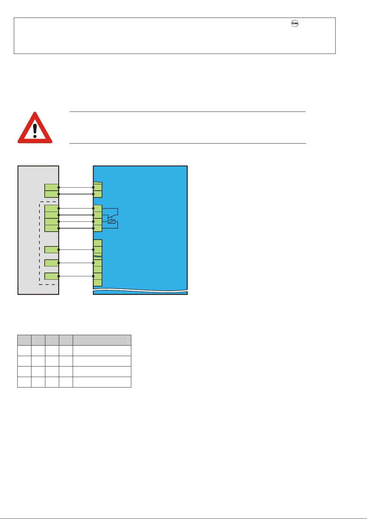
Figure 4-2 shows the wiring of the safety function "safe torque off." In our example the enable response message uses binary
output BA1.
3
4
16
19
GND
GND
E2
4
3
18
A1
A2
A4
2
10
17
A3
GND
E1 1
9
X1
X12
X101
Figure 4-3 Wiring of the safety function
Table 1 lists the states of the input and output signals during normal operation together with the related device states. When the
states of the signals on E1 and E2 are different from those indicated in the table, a malfunction has occurred. In such cases the
system must be put into a defined state.
A1 A2 E1 E2 Device State
0 0 1 1 Switchon disable
1 0 1 1 Switchon disable
0 1 0 1 Ready for switchon
1 1 0 0 Enabled
Table 1
InverterPLC
Safety circuit
Enable
ASP 5001
Options:
SEA 5000
REA 5000
or
XEA 5001
GND
Input
BA1
(A900 is
entered in F61)
24 V-In
A1: Address enable
A2: Address ASP 5001
E1: Response message ASP 5001
E2: Response message enable (A900)

POSIDRIVE®FDS 5000 – Mounting Instructions
STÖBER
ANTRIEBSTECHNIK
4. Electrical Installation
17
Switching on the inverter with the option "ASP 5001 starting lockout"
Proceed as follows (Figure 4-4):
nDeactivate the starting lockout by turning on the 24 V signal on
terminals X12.3 and X12.4.
ÖThe response message of the ASP 5001 contains a low signal.
YTurn on the enable.
ÖThe inverter replies with a low signal indicating that the enable is
turned on (e.g., via BA1).
ÖIf the application contains an activation of the halting brake, it is
enabled.
pWhen the brake has released, set the reference value to the reference
speed.
ÖThe drive accelerates to reference speed.
4.5.3 Function Test
You must perform a function test for:
•First commissioning
•Re-commissioning with a change in circuiting of a plant and use of option ASP 5001
•At least once a month during maintenance
The integration in the external safety circuit must also be checked. Proceed as described below.
Test of the safety function
1. Shut down all drives. Secure the hanging loads against crashing.
2. Address the ASP 5001 option by applying a 24 V signal to terminals X12.3 and
X12.4.
3. Turn off the enable.
ÖThe enable response message must then be active as a result.
4. Disconnect plug X12 from an inverter.
ÖThis should trigger the safety circuit.
5. Connect plug X12 again. Check the safety circuit.
6. Repeat steps 2 to 5 for each inverter.
7. Document the function test in your documentation.
4.5.4 Remaining Dangers
After a short circuit of two power transistors a remaining motion of up to 180°/pole pair can occur on the motor!
(Example: 4-pole motor Öremaining motion is a maximum of 180°/2 = 90°)
Include this remaining motion is your risk analysis (e.g., with the safety function "safe standstill" for main spindle drives).
Figure 4-4 Timing diagram
1
0t
1
0t
1
0t
1
0t
n
Ist
0t
n
Soll
0t
1
0t
[rpm]
[rpm]
Ref. value
Enable
A
ctivation
halting brake
(only if
integrated in
application)
ASP5001
Response
message
(X12.1, X12.2)
Enable
response
message
(e.g. via BA1)
Speed
Activation relay
of ASP 5001
(X12.3, X12.4)
X
Y
p

POSIDRIVE®FDS 5000 – Mounting Instructions
STÖBER
ANTRIEBSTECHNIK
4. Electrical Installation
18
4.6 Motor Cable Fabrication
Ready-to-use motor cables can be ordered from STÖBER ANTRIEBSTECHNIK.
The following modifications must be made for connection to the different model sizes.
BG 0 BG 1
20
160
20
240
All dimensions are recommended lengths which may vary depending on the installation site. [Dimensions in mm]
4.7 Installation after storage period
WARNING
Capacitors are installed in the inverter. After storage times of one year and longer, the capacitors must be
formed. If no forming is performed, substantial property damage may occur when the inverter is turned on.
Following a longer storage period, the capacitors of the inverter must be reformed. For the requirements, see the diagram
below.
10,50
0
25
50
75
100
2468
Core end
sleeves
Shield
Motor cable 4 x motor
2 x temperature
sensor
2 x brake
110 (+3 for PE)
Core end
sleeves
Shield
Motor cable 4 x motor
2 x temperature senso
r
2 x brake
160 (+3 for PE)
Storage time, 1 – 2 years: Before release, apply to voltage for one hour.
Storage time, 2 – 3 years: Before release, form as per curve.
Storage time, ≥3 years: Before release, form as per curve.
Storage time less than 1 year: No measures required
Time [h]
Connection
voltage
[%]
Other manuals for POSIDRIVE FDS 5000 series
3
This manual suits for next models
8
Table of contents
Other Stober DC Drive manuals

Stober
Stober RD11 User manual

Stober
Stober PS6 Series User manual

Stober
Stober POSIDRIVE MDS 5000 User manual

Stober
Stober FDS 4000 Installation and operation manual

Stober
Stober ASP 5001 User manual

Stober
Stober CANopen SD6 User manual

Stober
Stober Stober CombiDrive CM150/3 Installation and operation manual


