Kramer VW-9 User manual

Kramer Electronics Ltd.
VW-9 –Contents
i
Contents
Introduction 1
Getting Started 1
Overview 2
Typical Applications 3
Defining VW-9 3x3 Video Wall Driver with Multiviewer 4
Mounting VW-9 6
Connecting VW-9 7
Connecting the Output to an Unbalanced/Balanced Stereo Audio Acceptor 8
Connecting to VW-9 via RS-232 8
Operating and Controlling VW-9 9
Using Front Panel Buttons 9
Controlling Device via OSD Menu 10
Operating via Ethernet 16
Acquiring and Setting Current EDID Using RS-232 Serial Commands 19
Using VW-9 Embedded Webpages 20
Browsing VW-9 Webpages 21
Configuring the Screen Settings 22
Configuring the Output Resolution Settings 24
Managing EDID 24
Configuring the Screen Layout 25
Setting Up the Multi-Viewer Video Wall Page 26
Defining System Settings 33
Viewing the Ethernet Type (Static or HDCP) 33
Viewing the MAC Address 33
Changing the IP Address 33
Setting the Unit’s ID 34
Viewing the Fan Speed 35
Resetting VW-9 to its Factory Default 35
Resetting Device 35
Upgrading Firmware 36
Technical Specifications 37
Default Communication Parameters 38
Default EDID 38
Protocol 3000 41
Understanding Protocol 3000 41
Protocol 3000 Commands 42
Result and Error Codes 53

Kramer Electronics Ltd.
VW-9 –Introduction
1
Introduction
Welcome to Kramer Electronics! Since 1981, Kramer Electronics has been providing a world
of unique, creative, and affordable solutions to the vast range of problems that confront the
video, audio, presentation, and broadcasting professional on a daily basis. In recent years, we
have redesigned and upgraded most of our line, making the best even better!
Getting Started
We recommend that you:
•Unpack the equipment carefully and save the original box and packaging materials for
possible future shipment.
•Review the contents of this user manual.
Go to www.kramerav.com/downloads/VW-9 to check for up-to-date user manuals,
application programs, and to check if firmware upgrades are available (where appropriate).
Achieving Best Performance
•Use only good quality connection cables (we recommend Kramer high-performance,
high-resolution cables) to avoid interference, deterioration in signal quality due to poor
matching, and elevated noise levels (often associated with low quality cables).
•Do not secure the cables in tight bundles or roll the slack into tight coils.
•Avoid interference from neighboring electrical appliances that may adversely influence
signal quality.
•Position your Kramer VW-9 away from moisture, excessive sunlight, and dust.
Safety Instructions
Caution:
•This equipment is to be used only inside a building. It may only be connected to other
equipment that is installed inside a building.
•For products with relay terminals and GPI\O ports, please refer to the permitted rating
for an external connection, located next to the terminal or in the User Manual.
•There are no operator serviceable parts inside the unit.
Warning:
•Use only the power cord that is supplied with the unit.
•Disconnect the power and unplug the unit from the wall before installing.
•Do not open the unit. High voltages can cause electrical shock! Servicing by qualified
personnel only.
•To ensure continuous risk protection, replace fuses only according to the rating
specified on the product label which is located on the bottom of the unit.

Kramer Electronics Ltd.
VW-9 –Introduction
2
Recycling Kramer Products
The Waste Electrical and Electronic Equipment (WEEE) Directive 2002/96/EC aims to reduce
the amount of WEEE sent for disposal to landfill or incineration by requiring it to be collected
and recycled. To comply with the WEEE Directive, Kramer Electronics has made
arrangements with the European Advanced Recycling Network (EARN) and will cover any
costs of treatment, recycling and recovery of waste Kramer Electronics branded equipment on
arrival at the EARN facility. For details of Kramer’s recycling arrangements in your particular
country go to our recycling pages at www.kramerav.com/il/quality/environment.
Overview
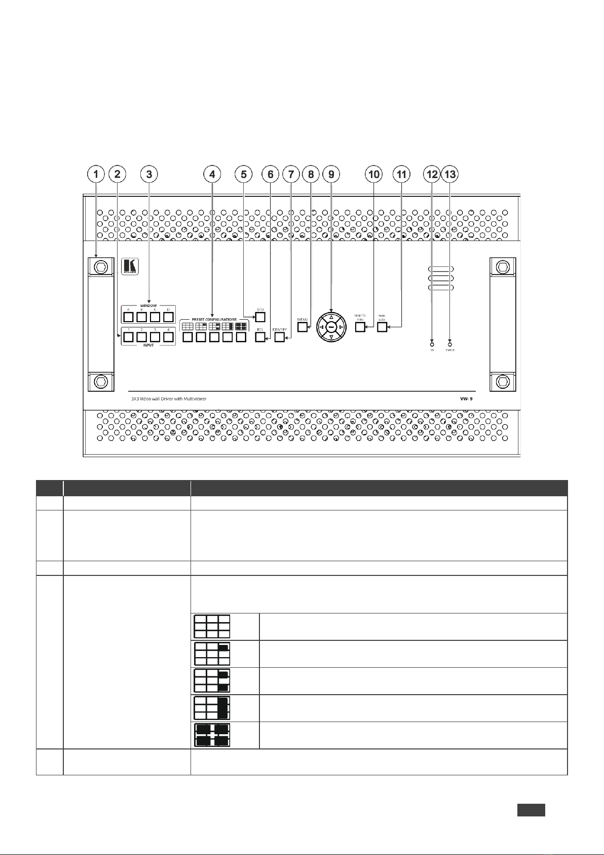
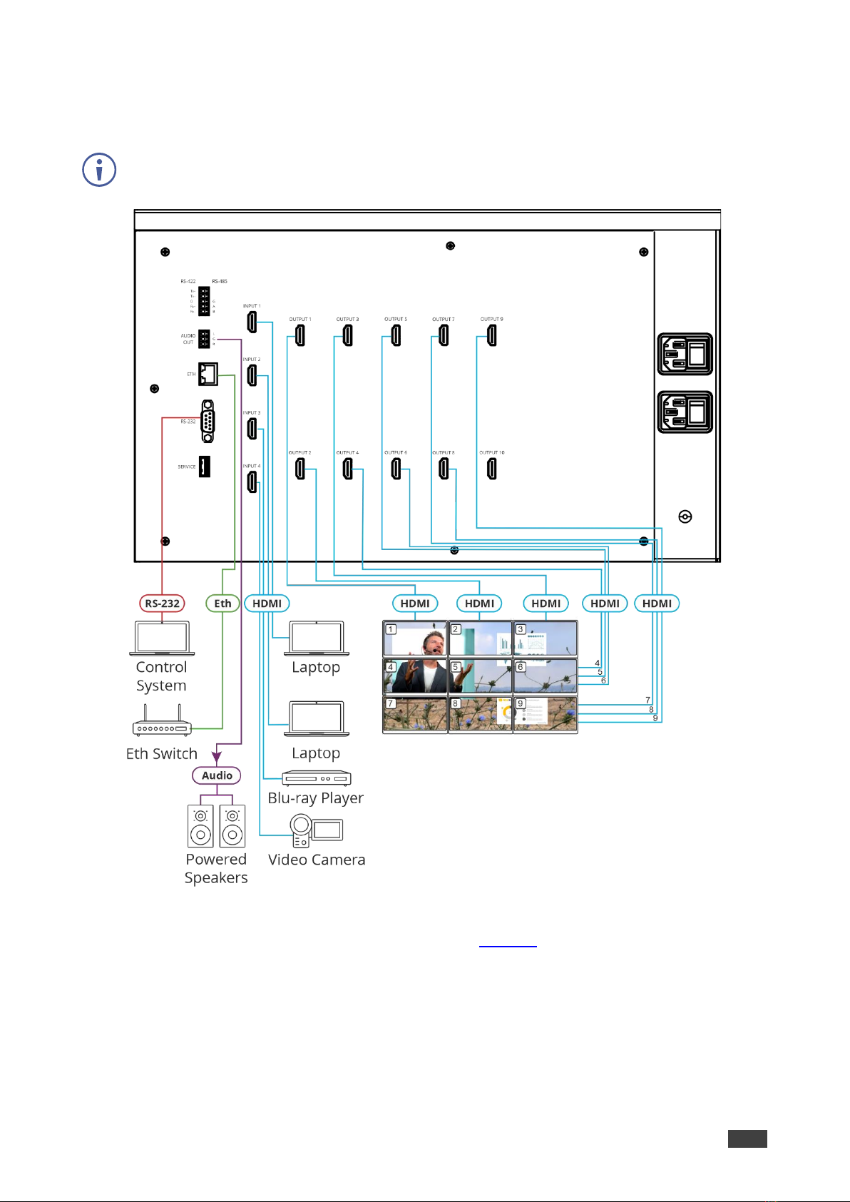
The VW-9 3x3 Video Wall Driver with Multiviewer is an all-in-one video-wall processor
system with multi-view, scaling, customizing screen layouts, and audio management
functions. Its user-friendly web interface, RS-232, RS-485, RS-422, and telnet modular design
allows you to effectively control the video wall both locally and remotely.
Its compact and robust design, reliability, multi-task features, and flexibility for either simple
digital signage display or large-scale control room video wall, and up to 4K resolution video
wall ability, represent a perfect partner for system integrators.
Exceptional Quality
•Input resolution up to 4K@60Hz, 4:4:4 color sampling.
•Output resolution up to 4K@60Hz, 4:4:4 color sampling.
•Upscaling up to 4K@60Hz, 4:4:4 color sampling and can downscale as well.
•Build various video wall array systems: 3x3, 2x5, 5x2, and more by 10 output model.
Advanced and User-friendly Operation
•Fast switching between input channels and combined multiple source images on video
wall.
•PiP, PoP, quad-view, and multiple customized screen layout configurations for video
wall.
•Clockwise and anti-clockwise 90° rotation in full screen layout.
•Controlled by web interface, RS-232, RS-485, RS-422, and telnet.
•Firmware upgrade via USB port with a USB flash drive.
•Display modes including video wall and multi-view window.
•Multiple windows display across multiple screen arrays without screen boundary.

Kramer Electronics Ltd.
VW-9 –Introduction
3
Flexible Connectivity
•Processes HDMI™® signals with Deep Color and HDCP 1.4/2.2 sources.
•Stereo audio output.
•Dual built-in power supply.
Typical Applications
VW-9 is ideal for the following typical applications:
•Signage in hotel lobbies, hospitals, and government offices.
•Conference room presentations.
•Advertising in shopping malls, supermarket, and restaurants.
•Airports, buses, and train stations.
•Rental and staging events.
•Monitoring in control rooms, banks, and stock markets.
•Security and surveillance systems.
Controlling your VW-9
Control your VW-9 directly via the front panel push buttons with on-screen menus, or:
•By RS-232 serial commands transmitted by a touch screen system, PC, or other serial
controller.
•Through the Ethernet using a built-in user-friendly web interface.

Kramer Electronics Ltd.
VW-9 –Defining VW-9 3x3 Video Wall Driver with Multiviewer
4
Defining VW-9 3x3 Video Wall
Driver with Multiviewer
This section defines VW-9.
Figure 1: VW-9 4x4 Video Wall Driver Front Panel
#
Feature
Function
1
Metal handles (x2)
Rigid metal handles for easy lifting.
2
INPUT Buttons (1 to 4)
After pressing a Window button (above), press an input button to select this input
for that window.
If the wall configuration has only one window, then pressing an input button will
select that input for the wall.
3
WINDOW Buttons (A to D)
Press to select window A, B, C or D.
4
PRESET
CONFIGURATION
Buttons
Press a configuration button to set one of the following presets (each window in
the Multiview mode can be resized and repositioned via the embedded
webpages):
Video wall mode –the video of one source only is presented over
the video wall.
Multiview mode, presenting 1 PiP window over a parent picture in
the video wall.
Multiview mode, presenting 2 PiP windows over a parent picture in
the video wall.
Multiview mode, presenting 3 PiP windows over a parent picture in
the video wall.
Multiview mode, presenting 4 windows over a 3x3 video wall.
5
STO Button
Press, followed by an Input button (1 to 4), to save the current video wall
configuration.

Kramer Electronics Ltd.
VW-9 –Defining VW-9 3x3 Video Wall Driver with Multiviewer
5
#
Feature
Function
6
RCL Button
Press, followed by an Input button (1 to 4), to recall a pre-saved video wall
configuration.
7
IDENTIFY Button
When pressed, identifies each window by displaying A, B, C or D in it.
8
MENU Button
Displays the OSD menu.
9
Navigation
Buttons
Press to decrease numerical values or select from several definitions.
When not in the OSD menu, press to reduce the output volume.
Press to move up the menu list values.
Press to increase numerical values or select from several definitions.
When not in the OSD menu, press to increase the output volume.
Press to move down the menu list.
ENTER
Press to accept changes and change the SETUP parameters.
10
RESET TO 1080p Button
Press and hold for about 5 seconds to set the output resolutions to 1080p.
11
PANEL LOCK Button
Press and hold to toggle locking and unlocking the front panel buttons.
12
ON LED
Lights green when power is on.
13
STATUS LED
Lights green when fan operates properly. Flashes in case of fan malfunction.
Figure 2: VW-9 4x4 Video Wall Driver Rear Panel
#
Feature
Function
14
SERVICE USB Port
Connect a USB flash drive to perform firmware upgrade.
15
RS-232 9-pin D-sub Serial Port Connector
Connect to a PC/serial controller.
16
ETHERNET RJ-45 Connector
Connect to a PC or other serial controller via a LAN.
17
5-pin Terminal
Block Connector
RS-422 (Tx+, Tx-, G,
Rx+, Rx-)
Connect to a PC/serial controller.
RS-485 (G, A, B)
18
AUDIO OUTPUT 3-pin Terminal Block
Connector (L, G, R)
Connect to an unbalanced stereo audio acceptor (for example,
powered speakers).
19
INPUT HDMI Connectors (1 to 4)
Connect up to 4 HDMI sources.
20
OUTPUT HDMI Connectors (1 to 10)
Connect up to 10 HDMI displays.
21
Grounding Opening
If required, use a M3 screw to lock the ground wire and connect
to ground.
22
Mains Power Connector and Power Switch
Plug in the power cord and use the switch to power the unit on or
off.

Kramer Electronics Ltd.
VW-9 –Mounting VW-9
6
Mounting VW-9
This section provides instructions for mounting VW-9. Before you start the installation, make
sure that the environment is within the recommended range:
•Operation temperature –0to 40C (32 to 104F).
•Storage temperature –-20to +60C (-4 to +140F).
•Humidity –0% to 80%, RH.
Caution:
•Mount VW-9 before connecting any cables or power.
Warning:
•Ensure that the environment, such as maximum ambient temperature & air flow, is
compatible for the device.
•Prevent uneven mechanical loading.
•Appropriate consideration of equipment nameplate ratings must be used to prevent
circuit overload.
•Reliable earthing of rack-mounted equipment must be maintained.
Mount VW-9 in a rack:
•Use the recommended rack adapter
(see www.kramerav.com/product/VW-9).
Mount VW-9 on a surface using one of these methods:
•Attach the rubber feet and place the unit on a flat surface.
•Attach both rack ears (remove the screws from each side of the
machine and replace those screws through the rack ears). For
more information, go to www.kramerav.com/downloads/VW-9.

Kramer Electronics Ltd.
VW-9 –Connecting VW-9
7
Connecting VW-9
Always switch off the power to each device before you connect it to your VW-9. After
connecting your VW-9, connect its power and then turn on the power to each device.
Figure 3: Connecting to the VW-9 Rear Panel
To connect VW-9 as illustrated in the example in Figure 3:
1. Connect up to four HDMI sources to the VW-9’s HDMI input ports via HDMI cables.
2. Connect up to 10 HDMI displays to the VW-9’s output ports via HDMI cables.
3. Connect a powered speaker or amplifier to the VW-9’s stereo audio terminal block
connectors.
4. Connect the power cord to the power socket.

Kramer Electronics Ltd.
VW-9 –Connecting VW-9
8
Connecting the Output to an Unbalanced/Balanced
Stereo Audio Acceptor
The following are the pinouts for connecting the output to a balanced stereo audio acceptor:
Figure 4: Connecting to a Balanced Stereo Audio Acceptor
Connecting to VW-9 via RS-232
You can connect to VW-9 via an RS-232 connection using, for example, a PC.
VW-9 features an RS-232 3-pin terminal block connector allowing the RS-232 to control
VW-9.
Connect the RS-232 terminal block on the rear panel of VW-9 to a PC/controller, as follows:
From the RS-232 9-pin D-sub serial port connect:
•Pin 2 to the TX pin on the VW-9 RS-232 terminal block
•Pin 3 to the RX pin on the VW-9 RS-232 terminal block
•Pin 5 to the G pin on the VW-9 RS-232 terminal block
RS-232 Device VW-9
15

Kramer Electronics Ltd.
VW-9 –Operating and Controlling VW-9
9
Operating and Controlling VW-9
Using Front Panel Buttons
Press the VW-9 front panel buttons to:
•Select the required INPUTs.
•Set the Multi-viewer screen setup.
•Use a pre-set configuration.
•Lock or Unlock the front panel buttons (see Locking and Unlocking Front Panel Buttons
on page 9).
•Reset the resolution to 1080p.
•Control the device via the OSD menu with the use of the MENU and navigation buttons
(see Controlling Device via OSD Menu on page 10).
•Store the current wall configuration.
•Recall a pre-saved video wall configuration.
•Identify each screen by displaying A, B, C, or D on the screen.
Locking and Unlocking Front Panel Buttons
The front panel buttons can be locked (disabled) to prevent unintentional pressing of the
buttons.
Locking Procedure
The locking procedure is the same for all locking modes.
To lock the front panel buttons:
•Press and hold PANEL LOCK for about 5 seconds.
The PANEL LOCK button lights red and the front panel buttons are locked.
Unlocking Procedure
Unlocking procedure is specific for locking modes.
To unlock the front panel buttons:
•For All or Menu Only Lock modes –Press and hold PANEL LOCK for about 5
seconds.
The PANEL LOCK button light turns off and the front panel buttons are unlocked.
11
11

Kramer Electronics Ltd.
VW-9 –Operating and Controlling VW-9
10
Controlling Device via OSD Menu
Use the OSD buttons to control the VW-9 via the OSD menu.
The default OSD timeout is set to 30 seconds.
•Navigating OSD Buttons on page 10.
•Configuring Screen Setting Parameters on page 11.
•Configuring the Video Wall on page 11.
•Configuring the Multi-Viewer on page 12.
•Viewing Device Information on page 16.
Navigating OSD Buttons
VW-9 enables you to control and define the device parameters via the OSD with the use of
the front panel MENU buttons.
To enter and use the OSD menu buttons:
1. Press MENU.
2. Press:
▪ENTER to accept changes and to change the menu settings.
▪Arrow buttons to move through the OSD menu, which is displayed on the video
output.
▪To exit the menu, select EXIT.
To return to the previous menu level, press the front panel MENU button. All settings and
adjustments are automatically saved in non-volatile memory for each of the inputs.
The values defined in the different menus may change according to the firmware version (you
can download the up-to-date firmware version from our Web site at
www.kramerav.com/support/product_downloads.asp).

Kramer Electronics Ltd.
VW-9 –Operating and Controlling VW-9
11
Configuring Screen Setting Parameters
VW-9 enables you to set the display settings, output resolution, and EDID.
To set the OSD display parameters:
1. On the front panel press MENU. The menu shows.
2. Select SCREEN SETTING > DISPLAY SETTING press Enter and define the image
parameters based on the information in the following table:
Menu Item
Function
Display Column
Set the horizontal position of the OSD.
Display Row
Set the vertical position of the OSD.
H.Bezel Correction
Set the horizontal Bezel correction.
V.Bezel Correction
Set the vertical Bezel correction.
Rotation
Select the rotation angle R90° (clockwise), L90° (anti-clockwise), or
Off (the default is Off).
OSD Display parameters are set.
To select the output resolution parameters:
1. On the front panel press MENU. The menu shows.
2. Select SCREEN SETTING > OUTPUT RESOLUTION press Enter and set the output
resolution parameters based on the information in the following table:
Menu Item
Function
Output Resolution
4096x2160@60Hz, 4096x2160@50Hz, 3840x2160@60Hz, 3840x2160@50Hz,
3840x2160@30Hz, 1920x1200@60Hz, 1920x1080@50Hz,1920x1080@30Hz,
1280x720@60Hz, 1280x720@30Hz, 1600x1200@60Hz, 1920x1200@60Hz,
2048x2048@57Hz
Output resolution parameters are set.
To manage the EDID:
1. On the front panel press MENU. The menu shows.
2. Select SCREEN SETTING > EDID and define the EDID parameters based on the
information in the following table:
Menu Item
Function
EDID
Default EDID (4K60).
EDID on Output 1
The Output 1 EDID is applied to all the inputs.
EDID is defined.
Configuring the Video Wall
To set the audio source:
1. On the front panel press MENU. The menu shows.
2. Select VIDEO WALL > AUDIO SOURCE press Enter and define the audio source
parameters based on the information in the following table:

Kramer Electronics Ltd.
VW-9 –Operating and Controlling VW-9
12
Menu Item
Function
MUTE
Mutes the audio.
INPUT 1 –INPUT 4
Select source to output audio: Inputs 1-4.
The video wall audio source is set.
To configure the color settings:
1. On the front panel press MENU. The menu shows.
2. Select VIDEO WALL > COLOR SETTING press Enter and define the color setting
parameters based on the information in the following table:
Menu Item
Function
Brightness
Adjust Brightness value between 0-100.
Contrast
Adjust Contrast value between 0-100.
Hue
Adjust Hue value between 0-100.
Saturation
Adjust Saturation value between 0-100.
The video wall color settings are set.
To set the aspect ratio:
1. On the front panel press MENU. The menu shows.
2. Select VIDEO WALL > ASPECT RATIO press Enter and define the aspect ratio
parameters based on the information in the following table:
Menu Item
Function
Full
Enlarge to full screen size.
Best Fit
Keep the original aspect ratio and enlarge to fit the screen automatically
either horizontal or vertical dimension.
Follow Input
Keep the original aspect ratio.
The video wall aspect ratio is set.
To set the video source:
1. On the front panel press MENU. The menu shows.
2. Select VIDEO WALL > VIDEO SOURCE, press Enter and define the video source
parameters based on the information in the following table:
Menu Item
Function
INPUT 1 –INPUT 4
Select a source to input vide: Inputs 1-4.
The video wall’s video source is set.
Configuring the Multi-Viewer
To set the audio source:
1. On the front panel press MENU. The menu shows.
2. Select MULTI-VIEWER > AUDIO SOURCE press Enter and define the audio source
parameters based on the information in the following table:

Kramer Electronics Ltd.
VW-9 –Operating and Controlling VW-9
13
Menu Item
Function
INPUT 1 –INPUT 4
Connect the speaker or amplifier to the stereo audio terminal block
connectors to VW-9 via the stereo audio cable.
The multi-viewer aspect ratio is set.
To configure the color settings:
1. On the front panel press MENU. The menu shows.
2. Select MULTI-VIEWER > COLOR SETTING press Enter and define the color setting
parameters based on the information in the following table:
Menu Item
Function
Brightness
Adjust Brightness value between 0 ~ 100.
Contrast
Adjust Contract value between 0 ~ 100.
Hue
Adjust Hue value between 0 ~ 100.
Saturation
Adjust Saturation value between 0 ~ 100.
The multi-viewer color setting is configured.
To configure the layout settings:
1. On the front panel press MENU. The menu shows.
2. Select MULTI-VIEWER > LAYOUT SETTING press Enter and define the layout setting
parameters based on the information in the following table:
Menu Item
Function
1-3 x PiP
Sets the multi-viewer mode to present 1, 2, or, 3 PiP windows over a
parent picture in the video wall.
Quad Split
Sets the source to output for each monitor. Set up each monitor 1, 2, 3, 4
individually.
Custom 1-7
Set the position and size of the windows of each custom screen layout
from Custom1 to Custom 7.
Single Picture
The video of one source is only presented over the video wall.
The multi-viewer layout settings are configured.
To set the video source:
1. On the front panel press MENU. The menu shows.
2. Select MULTI-VIEWER > VIDEO SOURCE press Enter and define the video source
parameters based on the information in the following table:
Menu Item
Function
WIN A
INPUT 1-4.
WIN B
INPUT 1-4.
WIN C
INPUT 1-4.
WIN D
INPUT 1-4.
The multi-viewer video source is set.

Kramer Electronics Ltd.
VW-9 –Operating and Controlling VW-9
14
To set the Unit ID source:
1. On the front panel press MENU. The menu shows.
2. Select SYSTEM >UNIT ID press Enter and set the unit’s ID parameters based on the
information in the following table:
Menu Item
Function
Unit ID
Indicate the ID of the unit. ID ranges between 0-100.
The Unit’s ID is set.
To view the MAC address:
1. On the front panel press MENU. The menu shows.
2. Select SYSTEM >MAC ADDRESS press Enter.
The MAC address shows.
To configure the RCL/STO:
1. On the front panel press MENU. The menu shows.
2. Select SYSTEM >RECALL/STORE press Enter and set the unit’s ID parameters based
on the information in the following table:
Menu Item
Function
STO
(Store)
Press, followed by an Input button (1 to 4), to save the current wall
configuration.
RCL
(Recall)
Press, followed by an Input button (1 to 4), to recall a pre-saved wall
configuration.
The RCL and STO are configured.
To configure the HDCP setting:
1. On the front panel press MENU. The menu shows.
2. Select SYSTEM >HDCP SETTING press Enter and set the HDCP setting parameters
based on the information in the following table:
Menu Item
Function
Input 1
ON/OFF
Set HDCP support on HDMI 1 to HDMI 4 inputs to ON (default) or
OFF. Note that: 1. HDCP must be enabled (ON) to support HDCP
encrypted sources. 2. Sources such as Mac computers always
encrypt their outputs when detecting that the sink supports HDCP.
If the content does not require HDCP, you can prevent these
sources from encrypting by disabling (OFF) HDCP on the input.
Input 2
ON/OFF
Input 3
ON/OFF
Input 4
ON/OFF
The HDCP settings are configured.

Kramer Electronics Ltd.
VW-9 –Operating and Controlling VW-9
15
To configure the network settings:
1. On the front panel press MENU. The menu shows.
2. Select SYSTEM >NETWORK SETTING press Enter and set the network setting
parameters based on the information in the following table:
Menu Item
Function
Ethernet Type
Select Ethernet type STATIC or DHCP.
IP Address
Indicates the systems current IP address.
For TCP/IPv4 you can use any IP address in the range 192.168.1.1 to
192.168.1.255 (excluding 192.168.1.39.
Default: 192:168:001:039.
Mask
255:255:255:000
Gateway
000:000:000:000
The network settings are configured.
To configure the OSD setting:
1. On the front panel press MENU. The menu shows.
2. Select SYSTEM >OSD SETTING,press Enter and set the OSD setting parameters
based on the information in the following table:
Menu Item
Function
H Offset
0-100
V Offset
0-100
Transparency
0-4
IDENT. Timeout
OFF/5-50
MENU. Timeout
OFF/5-50
INFO. Timeout
OFF/5-50
INFO. Display
ON/OFF
The OSD settings are configured.
To use the factory default:
1. On the front panel press MENU. The menu shows.
2. Select SYSTEM >FACTORY DEFAULT press Enter and set the factory default
parameters based on the information in the following table:
Menu Item
Function
ON
Use the factory default settings.
OFF
Do not use the factory default settings.
If “on” is selected, the device is reset to its factory default settings.

Kramer Electronics Ltd.
VW-9 –Operating and Controlling VW-9
16
Viewing Device Information
To view the input resolution:
1. On the front panel press MENU. The menu shows.
2. Select INFORMATION > INPUT RESOLUTION press Enter.
The input resolution for INPUT 1-4 show.
To view the output resolution:
1. On the front panel press MENU. The menu shows.
2. Select INFORMATION > OUTPUT RESOLUTION press Enter.
The output resolution shows.
To view the firmware version:
1. On the front panel press MENU. The menu shows.
2. Select INFORMATION > FIRWARE VERSION press Enter.
The output resolution shows.
To view the fan speed version:
1. On the front panel press MENU. The menu shows.
2. Select INFORMATION > FAN SPEED press Enter.
The fan speed shows.
Operating via Ethernet
You can connect to the VW-9 via Ethernet using either of the following methods:
•Directly to the PC using a crossover cable (see Connecting Ethernet Port Directly to a
PC on page 16).
•Via a network hub, switch, or router, using a straight-through cable (see Connecting
Ethernet Port via a Network Hub or Switch on page 18).
If you want to connect via a router and your IT system is based on IPv6, speak to your IT
department for specific installation instructions.
For info on configuring the Ethernet, see Defining System Settings on page 33.
Connecting Ethernet Port Directly to a PC
You can connect the Ethernet port of VW-9 directly to the Ethernet port on your PC using a
crossover cable with RJ-45 connectors.
This type of connection is recommended to identify the VW-9 with the factory configured
default IP address.
After you connect the VW-9 to the Ethernet port, configure your PC as follows:
1. Click Start > Control Panel > Network and Sharing Center.

Kramer Electronics Ltd.
VW-9 –Operating and Controlling VW-9
17
2. Click Change Adapter Settings.
3. Highlight the network adapter you want to use to connect to the device and click Change
settings of this connection.
The Local Area Connection Properties window for the selected network adapter shows
as shown in Figure 5.
Figure 5: Local Area Connection Properties Window
4. Highlight either Internet Protocol Version 6 (TCP/IPv6) or Internet Protocol Version 4
(TCP/IPv4), which is based on the requirements of your IT system.
5. Click Properties.
The Internet Protocol Properties window (specific to your IT system) shows as in Figure
6or Figure 7.
Figure 6: Internet Protocol Version 4 Properties Window

Kramer Electronics Ltd.
VW-9 –Operating and Controlling VW-9
18
Figure 7: Internet Protocol Version 6 Properties Window
6. Select Use the following IP Address for static IP addressing and enter the details as
shown in Figure 8.
For TCP/IPv4 you can use any IP address in the range 192.168.1.1 to 192.168.1.255
(excluding 192.168.1.39) provided by your IT department.
Figure 8: Internet Protocol Properties Window
7. Click OK.
8. Click Close.
Connecting Ethernet Port via a Network Hub or Switch
You can connect the VW-9 Ethernet port to the Ethernet port on a network hub or using a
straight-through cable with RJ-45 connectors.
Other manuals for VW-9
1
Table of contents
Popular DC Drive manuals by other brands

American Control Electronics
American Control Electronics VFD643-4 user manual

Allen-Bradley
Allen-Bradley 25-JBAA installation instructions

Grundfos
Grundfos CUE Safety instructions and other important information

Festo
Festo EMCA-EC-67 CO Series operating instructions

Sealey
Sealey VS4825 instructions

HIDROCONTROL
HIDROCONTROL W-DRIVEB2M2M/08 user manual