Stockcorner JC-4s User manual

JC-4s manual version 9.1 page 1
JC-4s auto tuner
1KW PEP DUAL MEMORY AUTO ANTENNA COUPLER
Highlights
-1Kwatt PEP (SSB) max power for 25 meter long antennas (1,6 –30 Mhz)
-50 memories in each antenna output (“A” and “B”)
-Antenna switching without retuning
-“tuned” start up at the last used frequency
-Memory storage without internal batteries
-Possible to connect with command from most Icom, Kenwood & Alinco transceivers
-Possible to connect with any HF radio with the provided control box
-6pF output capacitor steps
-Possible to connect a dipole direct to “A” & “B”
-Grounding of the not used antenna output while operating the other
-Grounding of both antenna outputs if the 12v DC supply is cut
-Improved design of the capacitor board (version S)
-Improved input SWR during the tuning process (version S)
-Improved security : When too much RF power during tuning process, Tuning will be interrupted
Chapters:
A Before you start
B Transceiver –Coupler control cable
C How is the control box working and connected
D Tuning procedure using the standard control box
E Memory operation
F Different antennas which can be used (just some examples)
G Remarks of tuner operation
H How to connect the JC-4 direct to your transceiver
I Specifications
J Wiring diagrams and antenna examples
K Intend of use and safety instructions
JC-4s manual version 9.1 page 2
A: BEFORE YOUR START First read this manual !
Some facts and hints for explanation.
1. Connect and use the provided control box before connecting it directly to your radio. By using this
control box you will understand very quickly how the tuner works.
2. If you do not select an antenna output on the control box (switch in middle position) the coupler does
not accept a “tune start” commando and remains frozen.
3. If you do not connect an antenna to the selected output you will have a very low reception and IF the
coupler manages to tune, it may be damaged when raising power to transmit. (even with 100 Watt) So
always connect a wire or antenna during testing.
4. When the user is using only 1 antenna output (like A) he should NEVER connect it simultaneously to
both outputs. (So never connect A and B together)
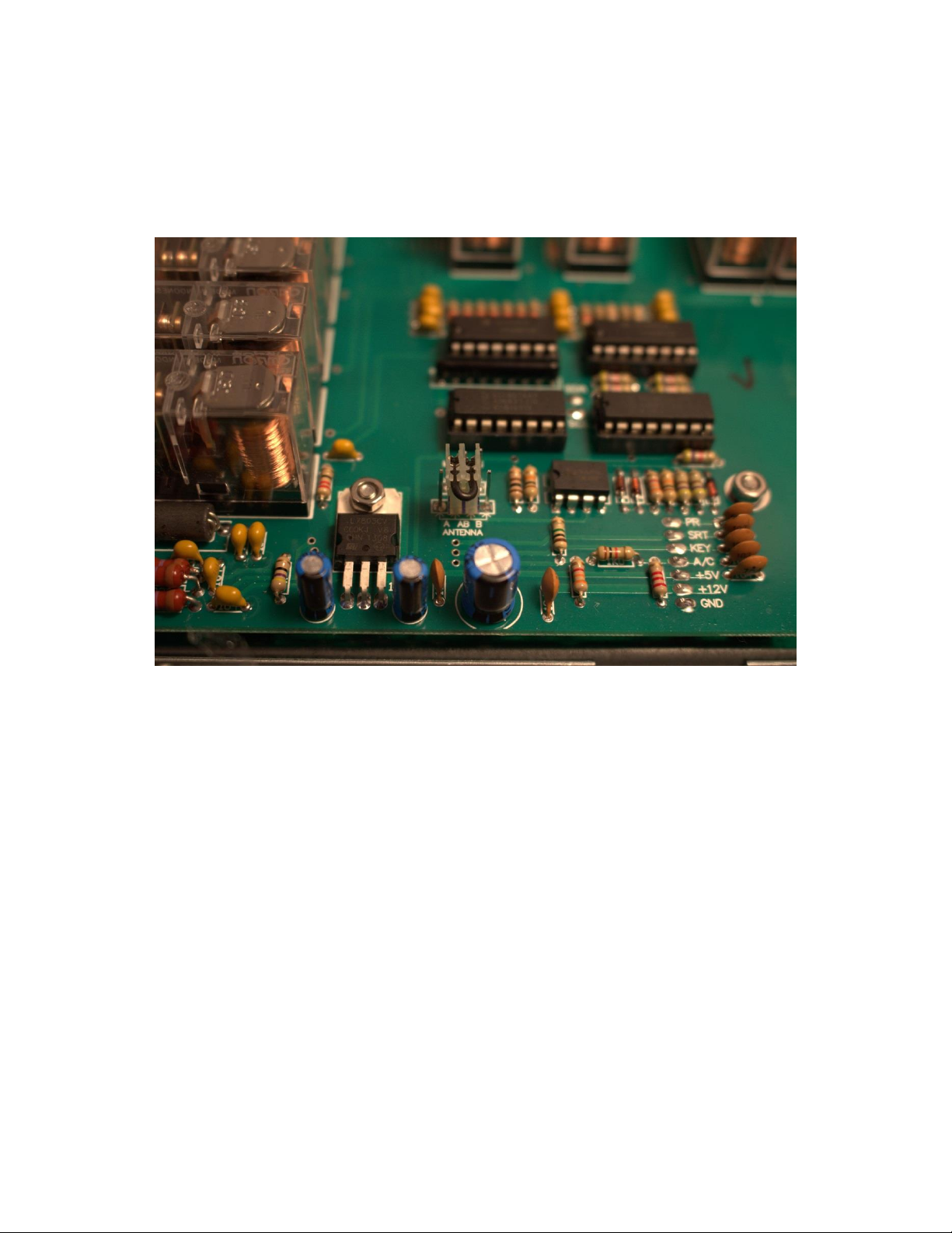
5. When a separate 12 volt power supply is used for the coupler, we must connect the “-“ terminal of
the separate power supply to the chassis of the transceiver. This is needed to return path of the power
supply is closed via the shield of the coaxial cable to the coupler. (see wiring diagrams in this manual)
6. When the 12 volt supply is not connected, both antennas outputs are disconnected and grounded! So
when the tuner is not in use the best possible protection of the coupler and transceiver is obtained.
7. During the operation of the tuner the coupler is still protected by a static discharge resistor and 2 x
600V ARC resistors in series.
B: TRANSCEIVER - COUPLER CONTROL CABLE:
4 x 0,50 mm or better if you use long lengths. (Brown, grey, yellow, black are the preferred colors but it
makes no difference). If you use a short control wire (< 25 meter) a normal UTP cable will do the job. But
it is common sense that UTP cable is not produced for 12 Volt DC voltage power feeding. UTP is used
only for low current data signals. For testing and short lengths you can use UTP but make use of all 8
wires. The control wire does not have to be shielded. But it is always better. As you can read that UTP is
doing the job almost all cables can be used.
DISTANCE
2-20 m.
DIAMETER
0.50 mm
20-35 m.
0.75 mm
35-50 m.
1.00 mm
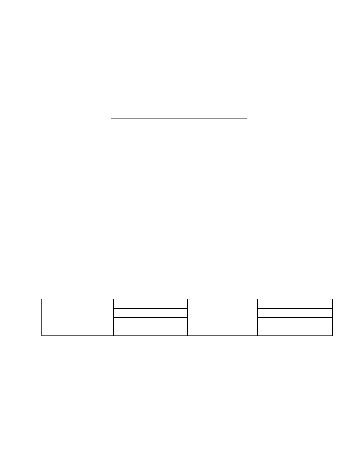
C: HOW IS THE CONTROL BOX WORKING AND CONNECTED?
This tuner JC-4 is controlled by 4 wires. These 4 wires you can easy find on the control box.
These 4 wires must be connected 1:1 from the control box to the tuner.
Function description of the 4 control wires:
Pin 1: (Brown) is +12 volt DC power connection (NOT the connection to your power supply)
JC-4s manual version 9.1 page 3
Pin 2: (Grey) is the Start commando to the tuner to start the tuning process.
If you connect this wire momentarily (pulse) to the GROUND the tuner will start tuning if RF power is
sended via the Coax Cable.
Pin 3: (Yellow/Green) This is the key (not ptt) connection. When the tuner is “tuning” it will send back a
voltage to a LED. (in the control box). When the tuning process is finished the led will go off.
Pin 4: (black) This is the control cable to switch antenna out A of B of the tuner.
If you connect pin 4 to the ground the tuner will use output A. If you connect pin 4 to +12V DC the tuner
will use output B. If you connect nothing to pin 4, The tuner output A and B will be connected internally
to the ground inside the tuner.
So the owner of the tuner can easy make his own design control box to his own demands.
Just open the small control box and discover how simple the design is.
The longer wires color RED and BLACK must be connected to your power supply. Logical, RED is the
positive connection.
Remember that if you do NOT use the same power supply for your transceiver and antenna tuner you
must add a jumper wire from the ground of the transceiver to the “-“ of your external power supply.
(So the Black of the red/black cable MUST be connected to the ground (chassis) of the radio)
This jumper wire is not provided with the tuner and can be any wire. (See diagram examples)
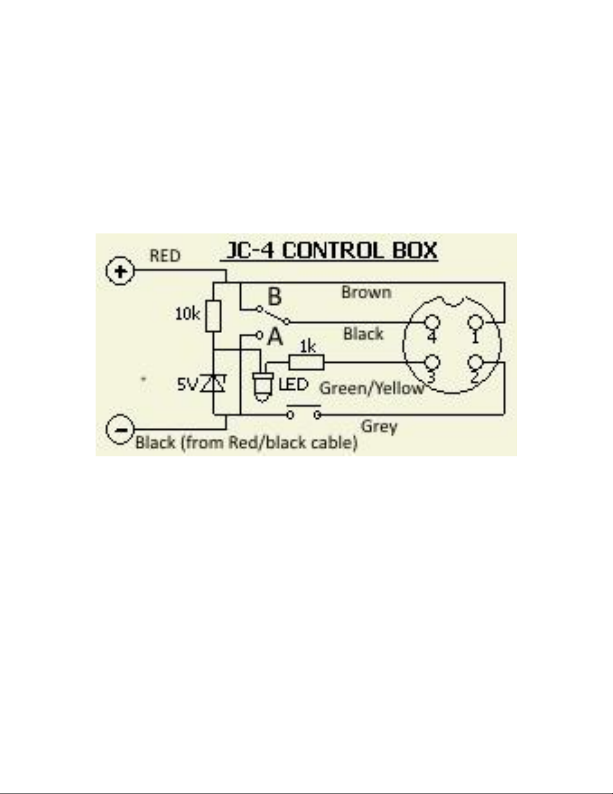
Pin 4 has to be explained more in combination with the jumper-switch inside the tuner on the top
board.
Very nearby the output A and B connectors you will find this jumper. Default this switch is jumpered to
the GROUNDED position. (totally left position) (see picture on next page)

JC-4s manual version 9.1 page 4
The function of this special jumper is sometimes very useful. It will control the antenna output which is
NOT selected with the control box. There are 2 reasons for this jumper. To easy connect a ladder line
450 ohm wire and to prevent RF back into the tuner while using higher powers when used with single
wires or verticals. In some cases it is better to ground OR to not connect the not used output.
Example 1:
So if you select and tune antenna output A:
Connect the jumper in de right position and antenna output B will be floating. (not connected to
anything)
Example 2:
So if you select and tune antenna output A:
Connect the jumper to the left position and antenna output B will be grounded

JC-4s manual version 9.1 page 5
Example 3:
So if you select and tune antenna output B:
Press the jumper in de right position and antenna output A will be floating. (not connected to anything)
Example 4:
So if you select and tune antenna output B:
Connect the jumper in the left position and antenna out A will be grounded
Example 2 & 4 are very handy if you like to use a ladder (open feedline) line like 450 ohm.
STANDARD CONTROL BOX WIRES
LONG RED & BLACK => 12VDC TO TRANSCEIVER POWER SUPPLY
SHORT BROWN => +12V TO COUPLER (PIN 1)
SHORT GREY => START TO COUPLER (PIN 2)
SHORT YELLOW => KEY TO COUPLER (PIN 3)
SHORT BLACK => ANTENNA CHANGE AND MEMORY CONTROL TO COUPLER (PIN 4)
D: TUNING PROCEDURE USING THE STANDARD CONTROL BOX
- We set the jumper switch of the control box to antenna "Α" or "Β".
- We set the transceiver in AM, FM, RTTY or CW mode and we adjust the output carrier power
somewhere in between 10 and 20 watts.
- We push the button on the control box until the red LED is lit
- We activate PTT keeping the transceiver transmitting some power.
- We wait until the LED goes off and then we stop transmitting. During this process you can hear
all relays fast clicking if you are nearby the coupler.
If the LED goes off the “tune process” is finished. (The SWR must be 1:1) If you push the tune button of
the control box and if you do NOT activate your transmitter the led will go off after a few seconds. (time
out) If the LED quickly turns on and off at the end of the tuning procedure, the tuning procedure has
failed!
E: MEMORY OPERATION
As soon as the coupler is supplied with 12V with the antenna change switch not in the middle (antenna
“A” or “B”), it is found tuned to the previously used frequency. If the switch was in the middle, the
coupler starts up in the “through” position. To operate the coupler without memories, the moment we
apply 12V to the coupler the antenna change switch must be in the middle position (the antenna change
line must be floating!) Afterwards, we can select the desired antenna, "Α" or "Β".
NOTE : The coupler does not memorize tunings with SWR > 1.3 : 1
To erase the memories from antenna “Α”, we must apply 12V to the coupler with the START
button pushed and the antenna change switch in antenna "Α". With the antenna change switch
in antenna "Β" we erase the memories from antenna "Β".

JC-4s manual version 9.1 page 6
When we have tuned both antennas to the same frequency, after having started the coupler for
memory operation, we can change antennas and use them immediately (without retuning every
time we change them)! So we have the capability to compare the antennas immediately without
having to tune each one of them while the propagation is changing!
Inside the tuner there are some more jumpers on the top board.
The 3 pin jumper is for selecting to use the memory function or not. Default the jumper is selected to Yes.
JC-4s manual version 9.1 page 7
The 4 pin jumper is to select the output of the tuner.
Totally left : Only output A will be used.
In the middle : You can control output A or B remotely with the control box (default)
Totally right : Only output B will be used.
Note :
If you want to use a 3 wire control cable with 1 antenna output you can use this jumper easy to
force to output A. To have the fun of 2 antenna outputs we recommend always to connect a 4
wire control cable. But if you use only a ladder line between A and B a 3 wire control cable will
do the job.
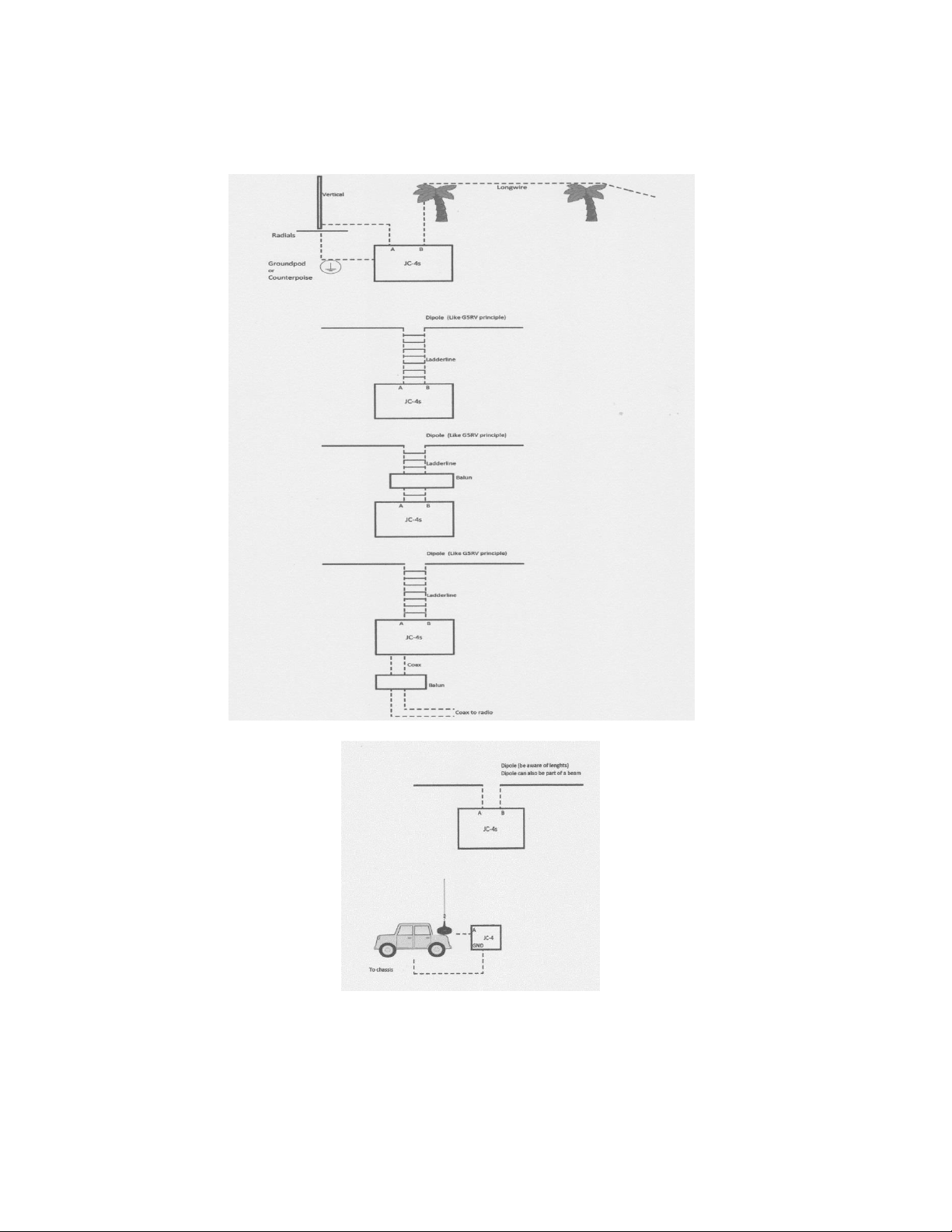
F: DIFFERENT ANTENNAS WICH CAN BE USED (just some examples)
1. Vertical antenna 6.5 meters long (without a coil in series or in parallel connected to its base) for a
better performance in the upper HF bands or 12 meters vertical if we don’t care for frequencies
higher than 18 Mhz.
2. Horizontal wire 25 –28 meters, or 46 –50 meters, with a diameter of at least 2 mm and a height
about 10m above the ground. For a real high performance, if we have the available space, it is
very good to place the wire about 20m above the ground, between two buildings. We note here
that anything that exists right below the antenna is considered as ground. So don’t go on believing
that if the antenna is placed 5 meters up from the roof of a building 20 meters high, the antenna
is 25 meters above the ground. The antenna considers the top of the building as ground!

JC-4s manual version 9.1 page 8
We surely understand that the above antennas 1 & 2 may be difficult to obtain in practice. The
purpose of the use of a coupler is to be able to operate your transceiver under the worst
conditions! That’s why we consider acceptable any antenna system that provides adequate wire
lengths to operate the coupler with the maximum power, if maximum power operation is the
goal.
The antennas suggested above demand an artificial ground system to operate. If this is by all
means impossible to be obtained in our house, we suggest the following types of antennas:
3. Unsymmetrical dipole with the longer wire connected to antenna B and the shorter wire to
antenna "Α" and the antenna switch for antenna “A” operation. (Internal antenna jumper selected
to “GROUNDED”!)
4. G5RV antenna type with open wire feeder (450 Ω) connected as the dipole case above. (Internal
antenna jumper selected to “GROUNDED”!)
We recommend to study the website of www.pa0fri.com and hit “ATU” and read this article about
the JC-4. A lot of explanation is written there.
Do NOT use a shortened 1:1 balun with a coil
between the connections A and B!!
In the webshop of Stockcorner we have ready made current baluns available. This baluns are
produced by our partner Ferrite Applications. The owner is Hugo ON7FU. This balun is specials
designed for Stockcorner tuners.
5. Many users use antenna solutions like an inverted L or even as a sloper.
G: REMARKS OF TUNER OPERATION
1. The closer we use an antenna to its resonant frequency (λ/4), the more power we can apply to it via
the coupler, because in this condition the coupler is using the least of its components to match the
antenna and there is no possibility of overheating inductors and capacitors!
2. The lower the power we use, the less restrictions apply for the used antenna. This means that
operating with the standard 100W, any antenna vertical or horizontal from 6 to 60 meters can be
used.
3. The performance of the system depends on the used antenna and counterpoise. The role of the
coupler ends when the SWR is reduced to the lowest in any case possible level. If at the particular
frequencies we wish to transmit the SWR is not low enough and going a little up or down in
frequency almost falls to 1 : 1, we can fix the problem by playing with the length of the antenna.
4. In case we face problems, we act as follows:
- We check and fix the counterpoise system.
- We ensure that any wires, cables or metal posts are located far enough from the antenna
and the directions are perpendicular to the antenna.
- We use another transceiver which is in a good condition to check the system.

JC-4s manual version 9.1 page 9
The counterpoise system is the most importance in antennas shorter or equal to λ/4. The shorter from
λ/4 an antenna is, the more it depends on the counterpoise system. As a general rule we can assume
that the electrical length of the counterpoise must be greater than that of the antenna. It is preferable
to place a metal grid, or many wires just below the ground terminal of the coupler then a long piece of
wire that is connected to some metal tube, water pipe or the actual ground (the earth).
The counterpoise must be as close as possible to the coupler!
If, when we finish the procedure, our transmission is satisfactory and all goes well, we don’t have to
worry any more, but if we detect holes at some frequencies or low performance in our
communications or «rf feedback», we must proceed to improvements. The general rule is that the
counterpoise must be connected primarily to the coupler and not to the transceiver!
ATTENTION!
WHEN THE COUPLER IS OPERATED NEAR MAXIMUM POWER, WE MUST NEVER USE HIGHLY
COMPRESSED TRANSCEIVER AUDIO BECAUSE AVERAGE POWER TENDS TO APPROACH THE PEAK
ENVELOPE POWER AND THE INDUCTORS AND CAPACITORS IN THE COUPLER WILL BE OVERHEATED!
FOR ANTENNAS 1, 3 & 4 NO GUARANTEE IS GIVEN FOR THE MAXIMUM POWER OF 1KW SSB IF THE
USER IS NOT FAMILIARIZED ENOUGH WITH THE SUBJECT. THE TYPICAL FORM OF ANTENNA THAT THESE
COUPLERS OPERATE IS ANTENNA CASE 2.
WE MUST NEVER RETUNE THE COUPLER WITH A LINEAR AMPLIFIER TURNED ON TO OBTAIN LOWER
SWR!
WE MUST NEVER OPERATE THE COUPLER IN THE THROUGH POSITION (or generally untuned) AND
ELIMINATE THE SWR USING ANOTHER TUNER NEAR THE TRANSCEIVER OR THE LINEAR AMPLIFIER.
WHEN THE COUPLER IS USED WITH A VACUUM TUBE LINEAR AMPLIFIER, THE FINAL TUNING OF THE
AMP MUST BE DONE VERY QUICKLY AND BY AN EXPERIENCED PERSON. THE BEST SOLUTION IS TO
TUNE YOUR AMPLIFIER ON A DUMMY LOAD.
NEVER PLACE ANOTHER HF ANTENNA VERY NEAR THE ANTENNA USED BY THE COUPLER. THE COUPLER
WILL NEVER TUNE NEAR THE RESONANT FREQUENCY OF THAT ANTENNA.
NEVER CREATE A COMPLICATED GROUND SYSTEM CONNECTING ALL GROUNDS IN YOUR HOUSE
TOGETHER WITH A BUNCH OF WIRES IF YOU DON’T KNOW HOW TO DEAL WITH IT
USE RUBBER TAPE TO ISOLATE YOUR CONNECTORS FROM WATER AND RAIN (LIKE VULCANISED TELCO
TAPE AND SO ON) . THIS TAPE IS NOT PROVIDED WITH THE COUPLER
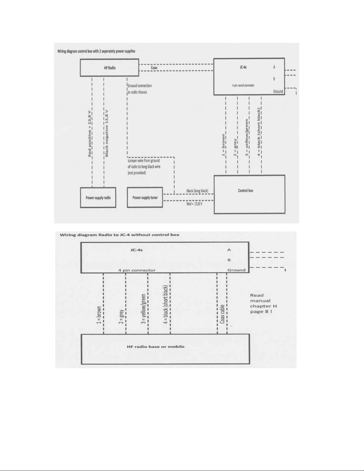
H: HOW TO CONNECT THE JC-4 DIRECT TO YOUR TRANSCEIVER
It is also possible to connect the JC-4 tuner direct to most Alinco, Icom and Kenwood transceivers.

JC-4s manual version 9.1 page 10
DIRECT CONNECTION BETWEEN COUPLER AND TRANSCEIVER OF THE BRAND YOU OWN.
YAESU
ALINCO
ICOM
KENWOOD
YAESU does not use the KEY-START
logic. They exchange data with their
transceivers using a single wire. So
the coupler can only cooperate with
YAESU transceivers with the standard
control box.
ΟΟΟΟΟ
Ο Ο Ο Ο
Ο
Ο
KEY
Ο
GND
GND
+12V
KEY
SRT
KEY
SRT
+12V
GND
Ο
SRT
Ο
+12V
(All the pins like described here on page 10 is the view to the chassis on the radio. Check the
connections with a multi meter to prevent damage.) You need a special connector to connect this.
We connect +12V, START and KEY of the JC-4 with the appropriate connector. Τhe GND of the
transceiver’s connector does not need to be connected to the COUPLER. The ground connection gets
there from the shield of the coaxial line! The MENU of the transceiver must be programmed, if needed.
(Or change a switch on the back of the transceiver to disable the internal tuner. Read the manual of your
transceiver to find this out). Remember that the tuner needs to know which output A or B has to be
selected. So if you still want to switch between A and B you have to add a small switch or force the tuner
with PIN 4 (tuner side) to ground to select output A. So YES you can use the ground connection to pin 4
of the tuner. (or use the internal jumper setting like described before)
I: SPECIFICATIONS
Circuit type
Reversible Lor Π
Input capacitance step
25pF
Output capacitance step
6pF
Inductance step
0.08μΗ
Total capacitance
3400pF
Total inductance
80μΗ
Impedance Range
About 10 –3000 Ohms
Used RELAYS
32 X OMRON
Operating frequencies
1.6 to 30 ΜΗΖ
Maximum power for 25 meters antenna
1000W SSB (300W on AM, FM, CW, RTTY & all other carrier modes FOR A
SHORT TIME!!! )
ATMEL controller
ΑΤ89C4051 -24P
Communication with RELAYS and memories
I2C
Maximum tuning power
50 W (carrier)
Typical tuning time
2 –3 sec.

JC-4s manual version 9.1 page 11
Maximum tuning time
Memory tune time
6 sec.
0.02 sec
D.C. supply voltage
11 –16 V
Maximum supply current
1.2A
Typical VSWR ( in the tuner input )
< 1.2 : 1
Maximum VSWR (in the tuner input)
< 1.6 : 1
Protection
Static discharge (NOT FOR THUNDER FALL!)
Dimensions ( without metal holder )
Weight
19.5 x 25 x 13.5 cm
2.5 Kg
Block schematic overview
JC-4s manual version 9.1 page 12
JC-4s manual version 9.1 page 13
Here down some antenna examples. There is no “best” solution. It all depends of your interest,
length of wires and space.
K : Intend of use:
- This device is designed to match 2 end-fed wires in the HF spectrum to a 50 ohm coax cable.
- Use of the JC-4s beyond the specified frequency or power range can destroy it and cause safety risks.
- This product must be considered as a sub assembly, intended to be a part of an amateur antenna
installation.
- This product is exclusively intended for outdoor use, in a fire safe and explosion safe environment.
JC-4s manual version 9.1 page 14
Important safety instructions:
- Read these instructions prior to installation of the product and heed warnings Retain this document.
- Apply during installation and use all possible safety countermeasures, like described in amateur radio
courses and literature.
- Install the product out of reach of persons and animals.
- Always install the product so that it cannot fall on persons or property.
- Do not attempt to modify the enclosure . Attempts to modify the enclosure will damage it and void
any warranty.
- Inspect the product on a regular basis and immediately replace if damaged.
- Install additional external lightning protection and earthing, as a means of secondary protection, and
disconnect the antenna wires during thunderstorms.
- Never work on the antennas or antenna wires during thunderstorms.
You will find the following “High Voltage Hazard” symbol on the product, indicating that the terminals
(just like the antenna itself) carry dangerous high voltages during transmission, and that caution is
required, in order to avoid electrocution or RF burns.
You will find the following "crossed out wheeled bin" symbol on the product, indicating that it can harm
the environment and it should be disposed of by the end user, separate from other types of waste.
In case of questions, please contact your local authorities regarding recycling.
Stockcorner Solutions: www.stockcorner.nl
Any questions you can email to: info@stockcorner.nl
The specifications and information regarding this product are subject to changes without prior notice.
All statements, information, recommendations and warnings in this user guide are deemed to be
accurate, but are given without any warranty. Users must take the full responsibility for the application
of the product.
Other Stockcorner Tuner manuals


