Grundig ST 16 User manual

Service Manual HiFi
ST 16
Zusätzlich erforderliche
Unterlagen für den Komplettservice
Additionally required
Service Manuals for the Complete Service
Service
Manual Service
Manual
Btx * 32700 #
Sachnummer
Part Number 72010-752.10
Änderungen vorbehalten
Subject to alteration
Printed in Germany
VK233 0297
Sicherheit
Safety
Sach-Nr./Part No.
72010-800.00
by
by
POWER
POWER
ST 16 DIGITAL SATELLITE TUNER
DMX
FREE
FAV
PTY
DMX
FREE
FAV
PTY
DISPLAY
ON/OFF
CANCELMEMORY
DISPLAY
ON/OFF
CANCELMEMORY
LEARN
LEARN
FAV DMX
MONO A/B
MONO A/B
ST 16
Sach-Nr./Part No.
72010-752.10

Allgemeiner Teil / General Section ST 16
1 - 2 GRUNDIG Service
Es gelten die Vorschriften und Sicherheitshinweise
gemäßdemServiceManual"Sicherheit",Sach-Num-
mer 72010-800.00, sowie zusätzlich die eventuell
abweichenden, landesspezifischen Vorschriften!
Theregulationsandsafetyinstructionsshallbevalid
as provided by the "Safety" Service Manual, part
number 72010-800.00, as well as the respective
national deviations.
GB
Table of Contents
Page
General Section............................. 1 - 2 … 1 - 8
Test Equipment / Aids ................................................................ 1 - 2
Disassembly Instruction ............................................................. 1 - 3
Display Test .............................................................................. 1 - 4
Specifications ............................................................................. 1 - 4
Notes......................................................................................... 1 - 4
Operating Hints .......................................................................... 1 - 7
Circuit Diagrams and
Layout of PCBs ........................... 2 - 1 … 2 - 20
Wiring Diagram ......................................................................... 2 - 1
Circuit Diagrams
Mains Unit Board, RC Board, Card Reader ......................... 2 - 3
Control Board, IR Board....................................................... 2 - 7
Main Board........................................................................... 2 - 9
Layout of PCBs
Mains Unit Board, RC Board, Card Reader ......................... 2 - 5
Control Board, IR Board....................................................... 2 - 5
Main Board......................................................................... 2 - 17
Display ...................................................................................... 2 - 6
Spare Parts Lists and
Exploded View............................... 3 - 1 … 3 - 2
Exploded View .......................................................................... 3 - 1
Spare Parts List ........................................................................ 3 - 2
D
Inhaltsverzeichnis
Seite
Allgemeiner Teil ............................ 1 - 2 … 1 - 6
Meßgeräte / Meßmittel ............................................................... 1 - 2
Ausbauhinweise ......................................................................... 1 - 3
Displaytest ................................................................................ 1 - 4
Technische Daten ...................................................................... 1 - 4
Hinweise ................................................................................... 1 - 4
Bedienhinweise .......................................................................... 1 - 5
Schaltpläne und
Druckplattenabbildungen........... 2 - 1 … 2 - 20
Verdrahtungsplan...................................................................... 2 - 1
Schaltpläne
Netzteilplatte, RC-Bus-Platte, Kartenleser........................... 2 - 3
Bedienteil, IR-Platte ............................................................. 2 - 7
Hauptplatte........................................................................... 2 - 9
Druckplattenabbildungen
Netzteilplatte, RC-Bus-Platte, Kartenleser........................... 2 - 5
Bedienteil, IR-Platte ............................................................. 2 - 5
Hauptplatte......................................................................... 2 - 17
Display ...................................................................................... 2 - 6
Ersatzteillisten und
Explosionszeichnung ................... 3 - 1 … 3 - 2
Explosionszeichnung ................................................................ 3 - 1
Ersatzteilliste............................................................................. 3 - 2
Allgemeiner Teil
Meßgeräte / Meßmittel
Beachten Sie bitte das GRUNDIG Meßtechnik-Programm, das Sie
unter folgender Adresse erhalten:
GRUNDIG electronics GmbH
Würzburger Str. 150
D-90766 Fürth/Bay
Tel. 0911/703-0, Fax 0911/703-4479
General Section
Test Equipment / Aids
Please note the Grundig Catalog "Test and Measuring Equipment"
obtainable from:
GRUNDIG electronics GmbH
Würzburger Str. 150
D-90766 Fürth/Bay
Tel. 0911/703-0, Fax 0911/703-4479

ST 16 Allgemeiner Teil / General Section
GRUNDIG Service 1 - 3
Ausbauhinweise
1. Öffnen des Gehäuses
- Die4SchraubenindenGehäuseseitenwändensowiedie2Schrau-
ben oben in der Gehäuserückwand herausschrauben und das
Gehäuse abnehmen.
2. Hauptplatte ausbauen
- SchraubeA(Fig.1) und2SchraubenB(Fig. 2)herausschrauben.
- Rastung C(Fig. 2) ausrasten.
- Leiterplatte herausheben, Steckverbinder nach Bedarf öffnen.
3. Frontblende ausbauen
- Rastung des Netzschalters ausrasten.
- 2 Rastnasen D(Fig. 3) ausrasten.
- Frontblende abnehmen, dabei Steckverbinder nach Bedarf öffen.
4. Frontblende zerlegen
- Frontblende ausbauen (Kap. 3).
- 2 Schrauben E(Fig. 4) herausschrauben und Rastnasen ausra-
sten.
5. Kartenleser ausbauen
- Schraube F(Fig. 5) herausschrauben.
- Kartenleser herausziehen.
Disassembly Instructions
1. Removing the cover
- Undo 4 screws on the sides of the cover and 2 screws on top of the
back of the cover and take off the cover.
2. Removing the Main Board
- Undo screw A(Fig. 1) and 2 screws B(Fig. 2).
- Unhook catch C(Fig. 2).
- Take off the board. Open connectors if necessary.
3. Removing the Front
- Unhook the catch of the Mains Switch.
- Unhook 2 catches D(Fig. 3).
- Remove Front, open connectors if necessary.
4. Disassembling the Front
- Remove the Front (para 3).
- Undo 2 screws E(Fig. 4) and unhook catches.
5. Removing the Card Reader
- Undo screw F(Fig. 5).
- Remove Card Reader.
Fig. 1 Fig. 2 Fig. 3
AB
B
C
D
Fig. 4
Fig. 5
EE
F

Allgemeiner Teil / General Section ST 16
1 - 4 GRUNDIG Service
MUTING MONO STEREO AUTO ANTENNA CABLE
MHz
kHz
BA
LOUD
DIRECTPRO-LOGIC
Displaytest
Aktivieren des Tests:
- Gerät ausschalten.
- Tasten "DMX" und "!" gedrückt halten und Gerät einschalten.
- Es werden jetzt nacheinander alle Segmente des Displays einge-
schaltet.
- Anschließend wird das interne EEPROM getestet. Ist dieses in
Ordnung so zeigt das Display:
Dislpay Test
Activating the Test:
- Switch off the unit.
- Hold the buttons "DMX" and "!" depressed and switch on the unit.
- Nowallsegmentsinthedisplaywillbeilluminatedoneafteranother.
- Now the internal EEPROM is being testet. If it is ok, the display
shows:
MUTING MONO STEREO AUTO ANTENNA CABLE
MHz
kHz
BA
LOUD
DIRECTPRO-LOGIC
Technische Daten
Frequenzbereich .................................................... 950 … 2050MHz
Eingangswiderstand...............................................................75Ohm
Eingangspegelbereich ................................................ 44 … 79dBµV
LNB Spannung............................................... 0, +13, +18V (400mA)
ZF-Bandbreite ........................................................................ 27MHz
Abstimmung
Transponderfrequenz..............................Schrittweite 1MHz mit AFC
Unterträgerfrequenz .............................................Schrittweite 10kHz
Abstimmbereich ........................... 0,36 bis 8,82MHz je Transponder
Transpondernutzung ............................................. 6,12 bis 8,46MHz
Audio
Audio-Bitrate .......................................................................192kBit/s
Brutto Bitrate 256kBit/s
Modulation .............................................................................. QPSK
Audio-Frequenzbereich............................................. 20Hz … 20kHz
Dynamikbereich Audio ............................................ 91,5dB (typisch)
S/N Audio ................................................................... 96dB (typisch)
Auflösung .................................................................................. 18Bit
Sampling-Frequenz................................................................. 48kHz
Klirrfaktor............................................................................... 0,003%
Kanaltrennung...............................................-100dB (20Hz - 10kHz)
Stromversorgung
Netzspannung......................................................................... 230V~
Netzfrequenz............................................................................. 50Hz
Max. Leistungsaufnahme........................................................ < 20W
Gehäuse
Abmessungen (B x H x T) ........................... 435 x 75(+12) x 310mm
Gewicht .....................................................................................3,5kg
Technical Data
Frequency range .................................................... 950 … 2050MHz
Input resistance......................................................................75Ohm
Input level range ........................................................... 44 - 79dBµV
LNB signal...................................................... 0, +13, +18V (400mA)
ZF-Bandwidth......................................................................... 27MHz
Tuning
Transponder frequency ................................... 1MHz steps with AFC
Sub-carrier frequency ....................................................10kHz steps
Frequency range ......... 0.36 - 8.82MHz (depending on transponder)
Transponder use .......................................................6.12 - 8.46MHz
Audio
Audio bitrate ........................................................................192kBit/s
bruto bitrate 256kBit/s
Modulation .............................................................................. QPSK
Audio frequency range.............................................. 20Hz … 20kHz
Dynamic range ......................................................... 91.5dB (typical)
Signal-to-noise ratio .................................................... 96dB (typical)
Resolution ................................................................................. 18Bit
Sampling frequency ................................................................ 48kHz
Total Harmonic Distortion ...................................................... 0.003%
Channel separation .................................... -100dB (20Hz … 10kHz)
Power supply
Mains voltage .......................................................................... 230V~
Mains frequency........................................................................ 50Hz
Max. power consumption ........................................................ < 20W
Cabinet
Dimensions (W x H x D).............................. 435 x 75(+12) x 300mm
Weight .......................................................................................3.5kg
Hinweise
DerSchalterS701auf der Hauptplatte mußeingeschaltetsein,da
sonst die Hauptplatte keine Betriebsspannung hat!
Notes
The switch S701 on the Main Board must be closed as otherwise
the Main Board has no power supply!

ST 16 Allgemeiner Teil / General Section
GRUNDIG Service 1 - 5
Bedienhinweise Hinweis: Dieses Kapitel enthält Auszüge aus der Bedienungsanleitung. Weitergehende Informationen entnehmen Sie bitte der gerätespezifischen Bedienungsanleitung, deren
Sachnummer Sie in der entsprechenden Ersatzteilliste finden.
Ein- und Ausschalten
• Schalten Sie Ihr Gerät ein, indem Sie den
Netzschalter POWER betätigen. Die Betriebs-
anzeige, eine gelbe LED in der Mitte des
Einschaltknopfes, informiert Sie über den
Schaltzustand: gedrückt: EIN
ausgerastet: AUS.
• Wollen Sie das Gerät ausschalten, drücken
Sie den Netzschalter POWER nochmals
(ausrasten).
• Haben Sie den TUNER an die Wechselspan-
nungs-Ausgänge AC OUTLETS des Verstärkers
angeschlossen, dient der Netzschalter des
Verstärkers als Zentralschalter. Lassen Sie den
Schalter POWER des Tuners immer gedrückt.
– Schalten Sie Ihr Gerät nach dem Auspacken
zum ersten Mal ein, wählt das Gerät den
ersten Sender der “freien” Programme.
– Jedes Mal, wenn Sie das Gerät wieder
einstellen, wählt es automatisch den Sender,
den Sie vor dem Ausschalten eingestellt hatten.
Vorderseite des Tuners
POWER Dieser Schalter wird zum Ein- und Ausschalten des Geräts verwendet.
DISPLAY ON/OFF Mit dieser Taste können Sie das Display Aus- und Einschalten.
LEARN Drücken Sie diese Taste während Sie den Tuner einschalten, um in das Installations-
menü zu gelangen. Drücken Sie diese Taste 2 Sekunden lang, um den automatischen
Suchlauf nach allen vorhanden Sendern zu aktivieren.
6
Falls DMX selektiert ist, wird diese Taste benutzt, um zwischen den Displayinformationen,
wie aktuelles Musikstück, Album, Interpret, Komponist und CD-Nummer zu wechseln.
FREE Mit dieser Taste wählen Sie die freien Programme.
DMX Mit dieser Taste wählen Sie die DMX-Programme.
1 2 Mit diesen Tasten schalten Sie die Programme (FREE, FAV oder DMX) in
aufsteigender (>) oder abfallender (<) Richtung durch oder laufen durch die verschie-
denen Installationsmöglichkeiten, wenn Sie sich im Installationsmodus befinden.
FAV
Mit dieser Taste wählen Sie Ihre Lieblingssender, in der FAV-Tabelle.
PTY
Mit dieser Taste wählen Sie die verschiedenen Programmarten an.
MEMORY Diese Taste speichert Installationseinstellungen und Radiosender als Lieblingssender.
CANCEL Mit dieser Taste löschen Sie einzelne Speicherplätze aus der FAV-Tabelle oder
Speicherpositionen die NO SIG(nal) angeben.
MONO A/B Wenn eine Sendeanstalt anstelle eines STEREO-Programmes zwei unterschiedliche
MONO-Programme sendet, können Sie mit dieser Taste zwischen den beiden
MONO-Programme umschalten.
BEDIENELEMENTE
by
by
POWER
POWER
ST 16 DIGITAL SATELLITE TUNER
DMX
FREE
FAV
PTY
DMX
FREE
FAV
PTY
DISPLAY
ON/OFF
CANCELMEMORY
DISPLAY
ON/OFF
CANCELMEMORY
LEARN
LEARN
FAV DMX
MONO A/B
MONO A/B
POWER DISPLAY
ON/OFF < >
LEARN 6MONO A/BCANCEL
MEMORY
FREE DMX FAV PTY
w
VOLUME
a
8
RC–SATELLITE TUNER
1
by
MONO
A/B
H/V
AUX
FREQUENCY
NAME 123
456
789
0
AB CD EF
CLASSIC POP OLDIES
PTY GH IJ KL
ROCK JAZZ COUNTRY
DMX MN OP QR
SPECIAL REGION NEWS
FREE
FAV
ST UV WX
YZ
GENERAL OK
STATION
PTY
FERNBEDIENUNG
NAME
Mit dieser Taste schalten Sie auf Senderauswahl nach Namen um.
PTY
Mit dieser Taste schalten Sie auf Wahl der Programmart um.
DMX Mit dieser Taste schalten Sie auf Wahl der DMX-Programme um.
FREE Mit dieser Taste schalten Sie auf Wahl der freien Programme um.
FAV
Mit dieser Taste schalten Sie auf Wahl der FAV-Tabelle (Ihre Lieblingssender) um.
Wahltasten Mit den Zifferntasten wählen Sie den Sender direkt an, oder wählen Sie die Programmart
(vorher Taste
PTY
drücken), oder geben Sie Buchstaben ein, um einen Sender über den
Namen auszuwählen, wenn zuvor die NAME-Taste gedrückt wurde.
O.K. Diese Taste wird zur Abstimmung auf einen Sender verwendet, der zuvor bereits über die
Namenssuche im Display angezeigt wurde. Außerdem wird sie benutzt, um Eingaben
über die direkte Frequenzeingabe zu bestätigen.
STATION 34 Mit diesen Tasten schalten Sie die Programme (FREE, FAV oder DMX) in
aufsteigender (3) oder abfallender (4) Richtung durch oder laufen durch die verschiede-
nen Installationsmöglichkeiten, wenn Sie sich im Installationsmodus befinden.
PTY
34 Mit diesen Tasten rufen Sie die Programmarten der Reihe nach auf.
MONO A/B Wenn eine Sendeanstalt anstelle eines STEREO-Programmes zwei unterschiedliche
MONO-Programme sendet, können Sie mit dieser Taste zwischen den beiden MONO-
Programme umschalten.
FREQUENCY Mit dieser Taste wählen Sie die direkte Frequenzeingabe an.
H/V Mit dieser Taste wählen Sie die Polarisation während der direkten Frequenzeingabe.
6
Falls DMX selektiert ist, wird diese Taste benutzt, um zwischen den Displayinformationen,
wie
aktuelles Musikstück, Album, Interpret, Komponist und CD-Nummer zu wechseln.
VOLUME +/- Mit diesen Tasten steuern Sie die Lautstärke des angeschlossenen Grundig Verstärkers.
aMit dieser Taste schalten Sie den angeschlossenen Grundig Verstärker stumm.
AUX Mit dieser Taste wählen Sie die AUX/DSR-Eingang am Verstärker an (falls vorhanden).
yMit dieser Taste schalten Sie den angeschlossenen Verstärker in STANDBY.
Wiedereinschalten mit einer der Eingangswahltasten.
Batteriewechsel
Läßt die Reichweite Ihres IR-Gebers nach oder lassen sich einzelne Funktionen nicht mehr ausführen,
sollten Sie die Batterien auswechseln.
Verwendeter Batterietyp 2x Micro 1,5 Volt LR03, Größe AAA. Öffnen Sie zum Batteriewechsel den
Deckel des Batteriefaches auf der Rückseite des Gebers. Achten Sie auf die richtige Polung der Batterien
(Markierung im Batteriefach beachten).
Umwelthinweis: Denken Sie beim Batteriewechsel daran: Batterien sind Sondermüll.
Aufstellen
• Wollen Sie Ihren
Tuner in Regalwänden,
Schränken, etc. aufstellen, sorgen Sie bitte für
ausreichende Belüftung des Gerätes. Ein
Freiraum von mindestens 3 cm seitlich und
oberhalb der Anlage sowie 5 cm an der
Rückseite sind empfehlenswert.
• Verlegen Sie Netzkabel möglichst entfernt von
den Tonsignal-Leitungen, um störende
Einstrahlungen zu vermeiden.
• Achten Sie beim Anschließen auf die Kenn-
zeichnungen der Leitungen bzw. Buchsen- oder
Rückwandbeschriftungen, um ein Vertauschen
der Anschlüsse zu vermeiden. Ein Verpolen der
Anschlüsse kann den Klangeindruck erheblich
beeinträchtigen.
•Wichtig: Alle Geräte ausschalten, bevor
irgendwelche Verbindungen hergestellt werden.
Anschluß am Verstärker
Schließen Sie Ihren TUNER an die entsprechen-
den Eingangs-Buchsen des Verstärkers an.
• Verbinden Sie dazu die Buchsen ANALOG
OUTPUT mit, vorzugsweise, den AUX
Eingängen des Verstärkers. Sind diese nicht
vorhanden, wählen Sie die Eingänge TUNER
oder CD des Verstärkers.
Achten Sie beim
Anschließen der Verbindungskabel auf die
r
ichtige Zuordnung der Stereo-Kanäle:
L= linker Kanal (weiß), R= rechter Kanal (rot).
• Falls Ihr Verstärker über einen digitalen
Eingang verfügt, verbinden Sie die Buchse
DIGITAL OUT Ihres Satellitentuners mit diesem
digitalen Eingang.
RC-BUS-Verbindung
• Um in der Lage zu sein, die Lautstärke Ihres
(Grundig) Verstärkers über die mitgelieferte
Fernbedienung zu steuern, verbinden Sie die
Buchse RC-BUS mit der Buchse RC-BUS Ihres
Verstärkers.
INSTALLATION
Netzanschluß
• Schließen Sie Ihr G
erät nur an Wechselspannung
230V~, 50/60 Hz an. Das Typenschild befindet
sich auf der Rückseite des Geräts.
• Wollen Sie Ihr Gerät zentral über einen Verstärker
dieser Serie einschalten und über die System-
Fernbedienung ausschalten, schließen Sie das
Gerät an einen der drei Wechselspannungs-
Ausgänge (AC OUTLETS) des Verstärkers an. Um
diese Funktion zu verwenden, stellen Sie sicher,
daß die Power-Taste des Tuners in Position “ON”
steht. Der Netzschalter des Verstärkers dient dann
als
Zentralschalter.
ANALOG
IN
RC-BUS
L
R
TV-RECEIVER
OUTPUT
RC-BUSDIGITAL
OUT MAINS ~
ANALOG
OUT DIGITAL
OUT
TV-RECEIVER
()
LNB
DC 13/18V
0.4A MAX
230V
~
50/60Hz
ANALOG
IN ANALOG
OUT LNB
INPUT
Satellitenanschluß
• Nach Möglichkeit sollten Sie eine Außeneinheit mit
TWIN-LNB einsetzen, um auch gleichzeitig unab-
hängig voneinander die Satellitenfernsehprogramme
und die digitalen Rundfunkprogramme empfangen
zu können.
• Falls Sie nicht gleichzeitig Fernseh- und digitale
Rundfunkprogramme empfangen möchten, können
Sie auch weiterhin Ihr V/H-LNB (Vertikal/Horizontal)
nutzen.
1. Anschluß des ST16 an ein TWIN-LNB
• Verbinden Sie den LNB INPUT Eingang des ST16
über ein geeignetes Koaxialkabel mit dem LNB Ihrer
Satellitenschüssel
.
2. Anschluß Ihres TV/SAT-Receivers und
des ST16 an ein V/H-LNB
• Auch hier verbinden Sie den LNB INPUT Eingang
des ST16 über ein geeignetes Koaxialkabel mit
dem LNB Ihrer Satellitenschüssel
.
• Dann verbinden Sie den
TV-RECEIVER OUTPUT Aus-
gang des ST16 mit dem
LNB Eingang Ihres TV/SAT-
receivers.
• In diesem Fall, bei eingeschaltetem ST16, können
Sie nicht alle Satellitenfernsehprogramme
empfangen.
• Sobald Ihr
ST16 ausgeschaltet ist,
wird die LNB-
Spannung vom TV/SAT-Receiver zum LNB durch-
geschaltet, und können Sie alle Satellitenfernseh-
programme empfangen.
• Desweiteren können Sie die AUDIO OUTPUTS Ihres
TV/SAT-Receivers an die ANALOG INPUTS Ihres
ST16 anschließen. Die Audiosignale des TV/SAT-
Receivers werden bei ausgeschaltetem ST16 zum
Verstärker weitergegeben.
INSTALLATION
ANALOG
IN
RC-BUS
L
R
ANALOG
OUT DIGITAL
OUT
TV-RECEIVER
()
LNB
DC13/18V
0.4AMAX
230V
~
50/60Hz
TV-RECEIVER
()
LNB
DC13/18V
0.4AMAX
230V
~
50/60Hz
CD
RC-BUS
L
R
PHONO AUX INTAPE OUT IN DCC OUT TUNER
SPEAKERSA OR B – 4ΩTO 8/16 Ω
LR
~
SWITCHED TOTAL 100W
SPEAKERSA AND B – 8ΩTO16 Ω
– –++
A
B
ST 16
AMPLIFIER TV
TV/SAT RECEIVER
LNB
230V
~
50/60Hz
TV/SAT RECEIVER
ANALOG
IN
RC-BUS
L
R
ANALOG
OUT DIGITAL
OUT
TV-RECEIVER
()
LNB
DC13/18V
0.4AMAX
230V
~
50/60Hz
CD
RC-BUS
L
R
PHONO AUX INTAPE OUT IN DCC OUT TUNER
SPEAKERSA OR B – 4ΩTO 8/16 Ω
LR
~
SWITCHED TOTAL 100W
SPEAKERSA AND B – 8ΩTO16 Ω
– –++
A
B
ST 16
AMPLIFIER
TV

Allgemeiner Teil / General Section ST 16
1 - 6 GRUNDIG Service
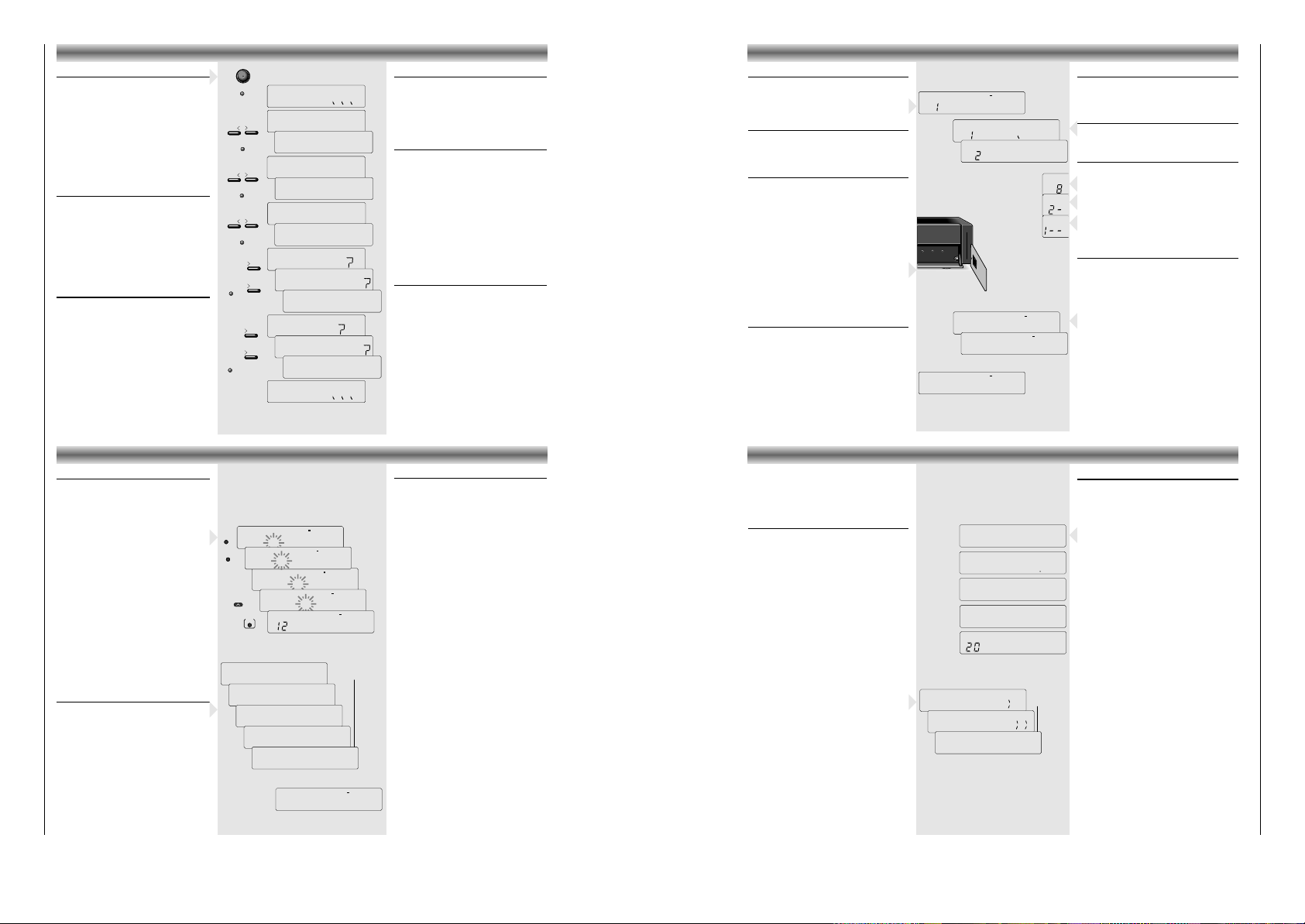
INSTALLATIONSMENÜ
Installationsmenü
Das Installationsmenü beinhaltet die wichtigsten
Grundeinstellungen zur Inbetriebnahme des
Tuners ST16.
• Schalten Sie Ihr Gerät aus.
•
Drücken Sie die LEARN-Taste drücken und schalten
Sie gleichzeitig den Tuner mit POWER wieder ein.
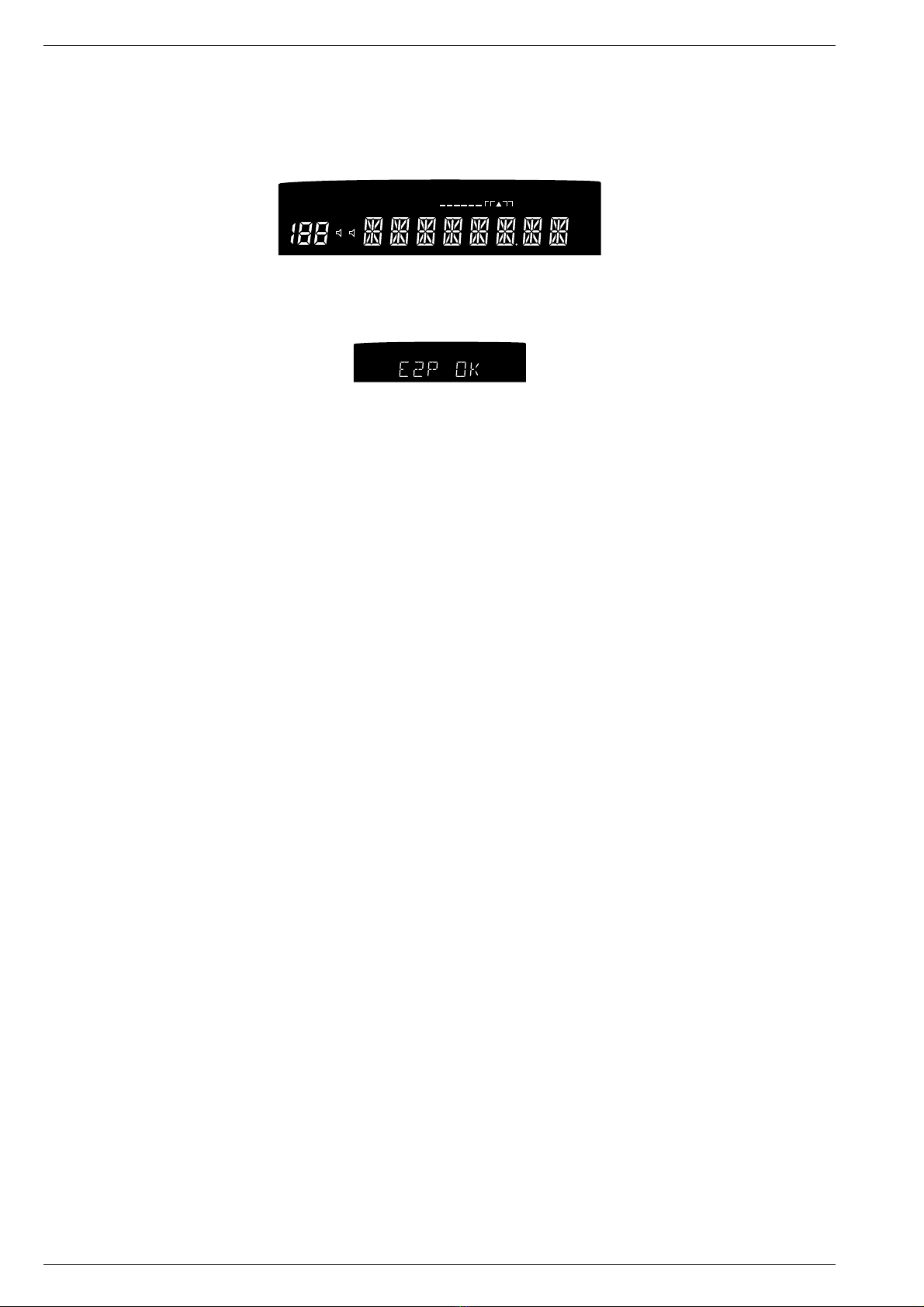
– Das Display zeigt WAIT...
Während dieser Zeit kopiert das Gerät den
Speicherinhalt, um notwendige Änderungen vorzu-
nehmen. Dieser Vorgang dauert ca. 30 Sekunden.
– Anschließend erscheint im Display die aktuelle
Sprache.
Umschaltung der Displaysprache
Sie können die Anzeige der Programmart (PTY)_
in verschiedenen Sprachen aufrufen
• Mit den Tasten 12können Sie die folgenden
Sprachen selektieren: ENGLISH, DEUTSCH,
FRANCE, ESPANA, PORTUGAL, NEDERLA.,
SVENSKA.
• Drücken Sie MEMORY, um Ihre Einstellung zu
speichern und zum nächsten Installationspunkt
zu gelangen.
– Das Display zeigt LOF 9750.
Lokal Oszillator Frequenz
Zur Anpassung des Tuners ST16 auf ältere
Außenanlagen können Sie die werkseitig
eingestellte LOF von 9.75 GHz ändern.
Evtl. vorhandene kleine Frequenzfehler werden
durch die automatische Feinabstimmung des
Tuners ausgeglichen.
• Mit den Tasten 12, kann die LOF auf
10.0 GHz gesetzt werden.
• Drücken Sie MEMORY, um Ihre Einstellung zu
speichern und zum nächsten Installationspunkt
zu gelangen.
– Das Display zeigt SC 1-14.
ENGLISH
DEUTSCH
LOF 9750
LOF10000
WAIT
SC 1-14
SC 1-48
CLEAR
COPY
WAIT
REALLY
CLEAR
REALLY
POWER
MEMORY
MEMORY
MEMORY
MEMORY
MEMORY
LEARN
+
➥
➥
➥
➥
➥
➥
➥
➡
➡ ➡➡➡➡➡➡
➡➡
➡➡
➡➡
➥
➥
TAB COPY
Frequenzbereich auf Unterträgern
Die Einstellung sollte immer SC 1-14 sein (die
andere Option 1-48 ist vorgesehen für zukünftige
Entwicklungen, wenn das Radio den Transponder
vollkommen belegen wird).
• Drücken Sie MEMORY, um Ihre Einstellung zu
speichern und zum nächsten Installationspunkt
zu gelangen. Das Display zeigt CLEAR.?
Alle Programme löschen
Falls Sie Ihren ST16 vollständig neu programmieren
möchten, können Sie den kompletten Programm-
speicher löschen.
Beachten Sie, daß
anschließend
neue Programme entsprechend LEARN
(siehe Seite
11) programmiert werden müssen.
• Drücken Sie 2, wenn Sie den Speicher
löschen möchten.
–
Das Display zeigt REALLY ?. Diese Sicherheits
-
abfrage wurde integriert, um ein unbeabsich-
tigtes Löschen aller Programme zu vermeiden.
•
Drücken Sie erneut 2, um den Speicher zu löschen.
– Das Display zeigt COPY ?
•
Wenn Sie den Speicher nicht löschen wollen, drücken
Sie MEMORY, um zum nächsten Installations-
punkt zu gelangen. Das Display zeigt COPY ?
Vorprogrammierung kopieren
Sie können den Senderspeicher, so wie er beim
letzten Durchlauf der LEARN-Funktion (siehe Seite 11)
konzipiert war, bei Bedarf wieder aufrufen, falls
Sie Ihre eigene Programmierung gelöscht haben.
•
Drücken Sie 2, wenn Sie das Senderprogramm
kopieren möchten. Das Display zeigt REALLY ?
• Möchten Sie das Programm nicht kopieren,
drücken Sie MEMORY.
• Zum Kopieren drücken Sie erneut
2
.
– Das Display zeigt TAB COPY
• Drücken Sie erneut MEMORY, um die Einstel-
lungen zu speichern und um das Installations-
menü zu verlassen.
Solange WAIT.. im Display sichtbar ist, speichert
das Gerät die Änderungen im Installationsmenü.
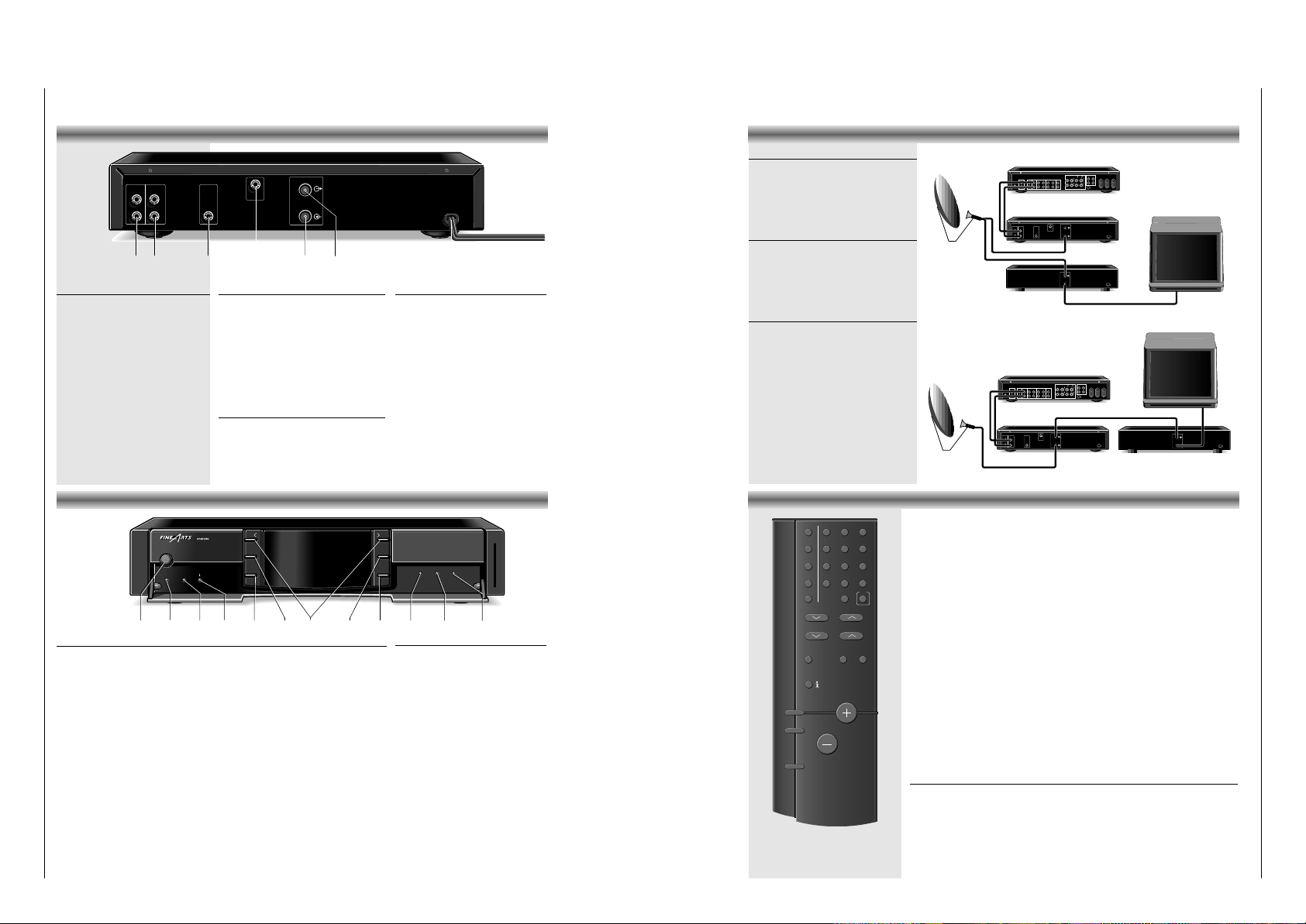
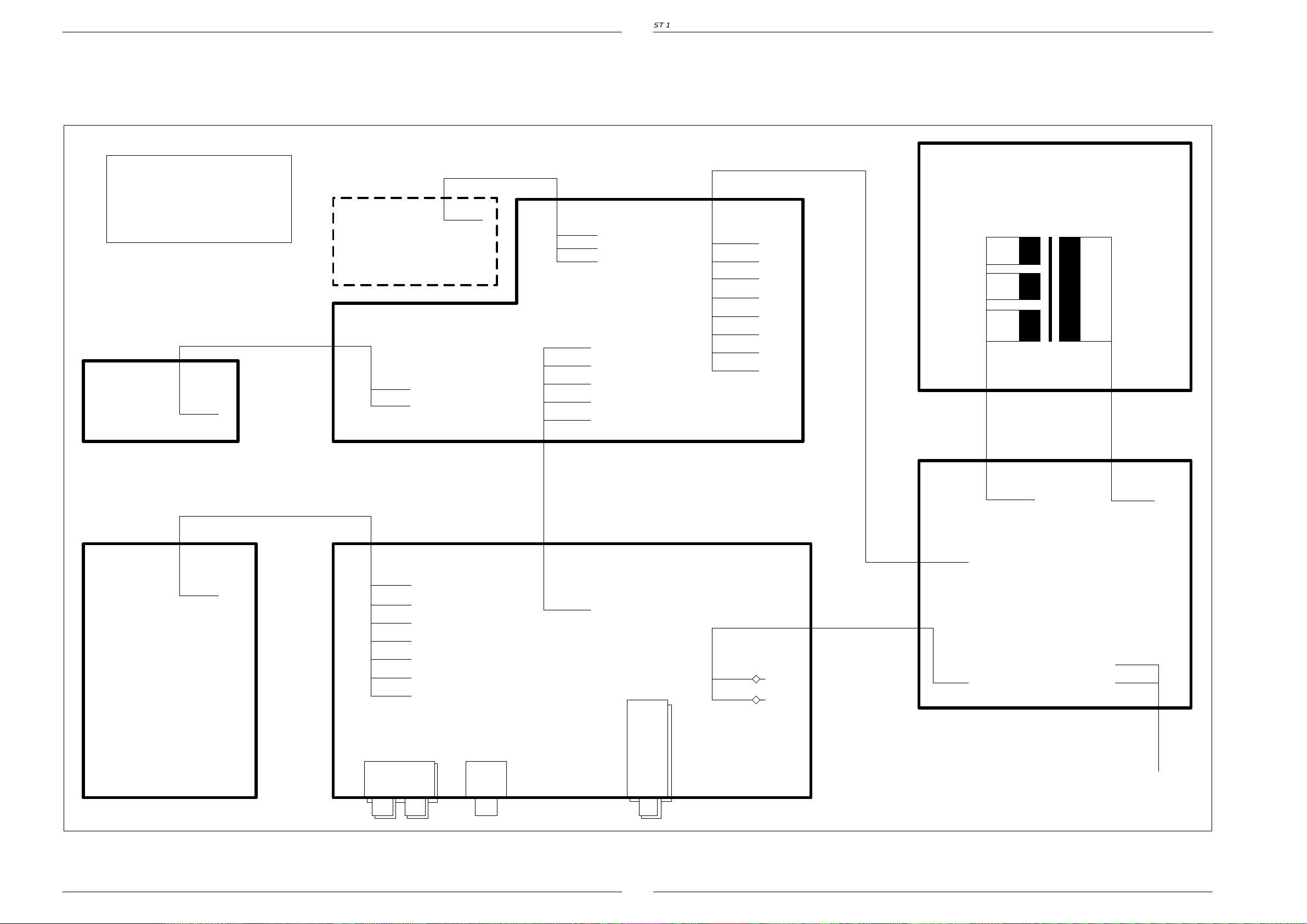
Radiosender
Es gibt zwei Arten von Radiosendern, die über den
Satelliten ASTRA empfangen werden können: die
sogenannten freien (FREE-to-air) und
DMX
-Sender.
Wenn kein Empfang möglich ist oder dieser sich als
zu schwach erweist, zeigt das Display NO SIG.
FREE-to-air-Sender
Bei den ‘freien’ Programmen handelt es sich um
bekannte, öffentliche Rundfunksender, die ihr
Programm in digitaler Tonqualität ausstrahlen.
•
Drücken Sie FREE, um die Tabelle FREE auszuwählen.
DMX-Sender
Weiterhin werden innerhalb des ADR-Systems Program-
me
vom ‘Digital Music Express’ (DMX) in codierter
Form ausgestrahlt. Zum Empfang dieser Programme
benötigen Sie den in Ihrem ST16 integrierten Decoder
und eine gültige Berechtigungskarte (‘Smart Card’)
,
für die eine Gebühr bezahlt werden muß.
Die beiliegende DMX Empfangskarte ermöglicht
Ihnen, bis zu 10 Tagen kostenlos alle DMX Kanäle
zu empfangen
. Die Zeit zählt ab der ersten Auswahl
von DMX mit eingeführter Karte.
Hinweis: Dieselbe Karte wird für den Empfang be-
nutzt, wenn die anfallenden Gebühren bezahlt sind.
Werfen Sie die Karte deswegen nach Ablauf der
10 Tage bitte nicht weg.
• Führen Sie die Karte mit der Seite, die den Chip
enthält nach links zeigend in den Tuner ein.
•
Drücken Sie DMX, um die Tabelle DMX auszuwählen.
Lieblingssender
In der FAV-Tabelle (für bevorzugte Programme) können
Sie Ihre Lieblingssender aus den freien und DMX-
Programmen speichern. Bis zu 99 Sender können in
diesem Speicher abgelegt werden.
•
Um Sender aus dem Speicher der Lieblingssender
aufzurufen, drücken Sie zunächst FAV.
– Haben
Sie auf dieser Tabelle noch keine Programme
gespeichert, erscheint im Display EMPTY und das Ge-
rät kehrt zu dem zuletzt angewählten Sender zurück.
Hinweis: Zum Speichern von Sendern siehe nächste Seite.
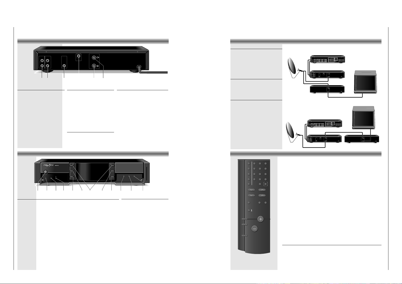
RADIOSENDER AUSWAHL VON SENDERN
FAV DMX
EMPTY
FAV DMX
ROCK
NONE
➥
CANCELMEMORY CANCELMEMORY MONOA/B
MONOA/B
➥
RAD ROPA
STAR*SAT
DMX
NO SIG
Auswahl von Sendern
• Drücken Sie FREE, DMX oder FAV, um die
jeweilige Tabelle auszuwählen. Ein strich im
Display leuchtet, wenn die Tabelle DMX
und/oder FAV selektiert wird.
Aufruf in Reihenfolge
• Drücken Sie die Tasten 1 2 (oder STATION $#
auf der Fernbedienung) um Programmplätze
nacheinander aufzurufen.
Direkte Eingabe der Sendernummer
• Sie können auch mit den Zifferntasten 0-9 auf der
Fernbedienung die Nummer direkt eingeben:
– Bei einstelligen Programmnummern betätigen Sie
die entsprechende Zifferntaste nur kurz.
– Bei zweistelligen Zahlen halten Sie die erste Zahl
gedrückt, bis diese eine Stelle nach links
“springt”, dann geben Sie die zweite Zahl ein.
– Für dreistellige Zahlen halten Sie die erste Zahl
gedrückt, bis diese zwei Stellen nach links springt.
Geben Sie dann die zwei weiteren Zahlen ein.
Auswahl nach Programmart
• Durch mehrmaliges Drücken der Taste
PTY
am
Gerät, können Sie die Programmarten nachein-
ander aufrufen.
– Lassen Sie die Taste
PTY
los, beginnt das Gerät
die Sender zu scannen, um die gewünschte
Programmartübertragung zu finden. Sobald dies
der Fall ist, wird der Sender eingestellt.
– Wird die aktuelle Kennung von keiner Station
übertragen, zeigt das Display für kurze Zeit:
'
NONE
' ('KEINE').
•
Drücken Sie nochmals PTY, um den nächsten Sen-
der innerhalb dieser Programmart auszuwählen.
• Zur Auswahl der Programmart über die Fernbe-
dienung drücken Sie zunächst
PTY
und
anschließend die gewünschte Programmart oder
verwenden Sie die PTY $#Tasten.
Die definierten Programmarten sind: CLASSIC, POP,
OLDIES, ROCK, JAZZ, COUNTRY, SPECIAL,
REGIONAL, NEWS und GENERAL.
Senderauswahl nach Namen
• Die Auswahl der Sender gemäß ihres Namens
kann über die Fernbedienung getätigt werden.
•
Um gute Funktionalität bei der Suche nach Namen
sicherzustellen, muß das Gerät wenigstens einmal
auf alle Sender abgestimmt werden, damit die
Namen im Speicher abgelegt werden.
• Drücken Sie FREE, DMX oder FAV, um die
jeweilige Speicherbank auszuwählen.
•
Drücken Sie zuerst NAME und anschließend den
ersten gewünschten Buchstaben des Namens.
Z.B. für ‘F’ drücken Sie zweimal EF/3/OLDIES
– Nach zwei Sekunden springt der Cursor nach
rechts und Sie können, wenn Sie wünschen,
den zweiten Buchstaben eingeben.
• Drücken Sie STATION #. Im Display erscheint
der erste Name mit
‘F_’
beginnend.
• Drücken Sie nochmals STATION #, um andere
Sender mit
‘F_’
zu suchen.
• Wird der gewünschte Sender angezeigt,
drücken Sie OK, um den Sender anzuwählen.
Hinweis: Wenn Sie einen vollständigen Namen
eingeben, sollten Sie davon absehen spezielle
Zeichen zu verwenden, die weder eine Zahl
noch ein Buchstabe aus dem Alphabet sind.
Z.B. für STAR*SAT sollten Sie STARSAT eingeben.
Ändern der Displayanzeige
DMX überträgt auch Information über das aktuelle
Musikstück, die im Display Ihres ST16 angezeigt
wird.
•
Drücken Sie 6, um den Titel des spielenden Musik-
stücks aufzurufen. Im Display erscheint erst TITLE,
danach wird der Titel in Laufschrift angezeigt.
• Drücken Sie erneut 6, wenn Sie den Interpreten
des Stücks wissen möchten.
–ARTIST erscheint im Display, danach wird
der Interpret in Laufschrift angezeigt.
•
Setzen Sie diese Vorgehensweise fort, um Infor
-
mationen zu ALBUM, COMPOSER und CD NR
zu erhalten.
AUSWAHL VON SENDERN SPEICHERN BEVORZUGTER SENDER
Speichern bevorzugter Sender
• Wählen Sie den Sender, den Sie speichern
möchten aus (in freiem oder DMX-Modus).
• Drücken Sie die Taste MEMORY.
– Der Sender wird auf den nächsten freien
Speicherplatz gelegt. Sie müssen also keine
Speicherplatznummer eingeben.
– Der erste gespeicherte Sender erhält die
Speicherplatznummer 1, der nächste Sender
die Nummer 2 und so fort.
• Möchten Sie einen bereits gespeicherten
Sender ‘verschieben’, d.h. auf einen anderen
Speicherplatz legen, drücken Sie MEMORY.
– Der Sender wird immer auf den ersten freien
Speicherplatz gelegt.
•
Drücken Sie MEMORY mehrmals, werden die freien
Speicherplätze der Reihe nach durchgetastet.
• Speichern Sie auf gleiche Weise alle anderen
Sender Ihrer Wahl.
Sender auswählen
• Um einen Sender aus dem Speicher Ihrer
bevorzugten Programme aufzurufen, drücken
Sie erst die Taste FAV.
• Anschließend wählen Sie den Sender aus, wie
vorher beschrieben.
Speicherplatz löschen
• Wollen Sie einen belegten Speicherplatz
wieder löschen, frei-machen, rufen Sie zuerst
seine Nummer auf.
• Drücken Sie die Taste CANCEL.
– Der Sender ist aus dem Speicher gelöscht, die
Anzeige FAV erlischt und im Display erscheint
wieder die freie oder DMX-Speichernummer
dieses Senders.
• Beim Drücken der Taste FAV, wenn alle
bevorzugten Sender gelöscht wurden,
erscheint EMPTY im Display.
•
Sender der Tabellen DMX und FREE können nur
gelöscht werden, wenn im Display NO SIG
erscheint.
FAV DMX
EMPTY
➥
TITLE
ARTIST
➥
➥
ALBUM
COMPOSER
➥
CD NR
➥
DMX
_
➥
➥
➥
F_
FOLKROCK
➥
FOLKROCK
F
NAME
EF
OLDIES
STATION
OK
3
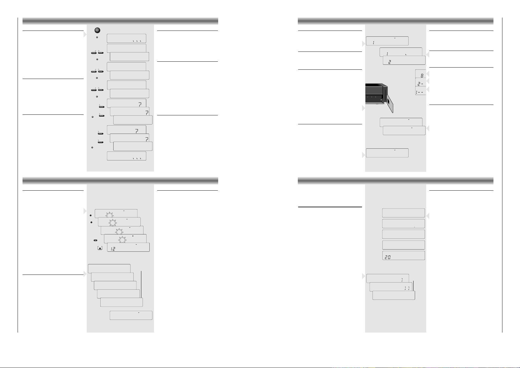
Der ST16 ist werkseitig auf die zur Zeit aktuellste
Belegung aller digitalen Astra-Rundfunkprogramme
vorprogrammiert (vorhandene Sender zur Produktions-
zeit). Es ist auch möglich, neue Sender auf einfache
Weise hinzuzufügen.
Automatische Suche nach neuen Sendern
Um neue ADR-Programme, deren Empfangsdaten
Ihnen unbekannt sind, speichern zu können, verfügt
der ST16 über ein automatisches Programmier-
system (LEARN). Dieses Programmiersystem speichert
automatisch alle störfreien empfangbaren digitalen
Rundfunkprogramme des Astra-Systems in die
richtige Tabelle FREE oder DMX.
Der Vorgang dauert ungefähr 30 Minuten.
Ihre
individuell zusammengestellte Tabelle FAV bleibt
davon unberührt.
Das LEARN-System speichert die freien Programme
fortlaufend nach aufsteigender Speichernummer und
die DMX-Programme entsprechend ihrer mit über-
tragenen Programmnummer.
Ein wiederholter Lauf von LEARN löscht kein Programm,
das momentan nicht empfangbar ist, ergänzt jedoch
die bestehenden Tabellen mit neuen Programmen
.
• Drücken Sie die LEARN-Taste für mehr als 2
Sekunden.
– Der automatische Suchlauf beginnt; im Display
erscheint LEARN >>.
– Sobald ein Sender gefunden wurde, wird die
Nummer des Senders links im Display angezeigt.
– Die DMX LED leuchtet auf, wenn ein DMX-Sender
gefunden wurde.
– Nachdem der Suchlauf beendet ist, wählt das
Gerät den Sender Nummer 1 der freien Programme.
• Das LEARN-system kann durch Drücken der Taste
POWER unterbrochen werden. Die bereits
existierenden Speicher der DMX- und freien
Programme bleiben unverändert bestehen.
LEARN DIREKTE FREQUENZEINGABE
➥
LEARN
LEARN
➥
LEARN
➥
SWF1 BW
MHz
TR 11186
MHz
SC 666
POL VERT
STEREO
Direkte Frequenzeingabe
Satellitenmagazine informieren regelmäßig über
neue Radiosender, die über Astra-Satelliten zu
empfangen sind. Damit Sie nicht über 30 Minuten
verlieren, um einen oder vielleicht zwei neue Sender
in Ihre Tabelle mit aufzunehmen, ist der ST16 mit
einem direkten Eingabemodus ausgestattet.
•
Drücken Sie FREQUENCY auf der Fernbedienung.
– Das Display zeigt die Transponderfrequenz, des
aktuell ausgewählten Senders.
• Geben Sie die Transponderfrequenz mit den
Zifferntasten von links nach rechts ein.
•
Sie können auch die Tasten STATION $#benutzen,
um jeweils 1 MHz herauf oder herunter zu gehen.
– Nach der letzten Ziffer stellt das Gerät sofort die
Frequenz ein.
• Drücken Sie nochmals FREQUENCY.
–
Im Display erscheint die aktuelle Unterträgerfrequenz.
• Geben Sie die
Unterträger
frequenz mit den
Zifferntasten von links nach rechts ein.
•
Sie können auch die Tasten STATION $#benutzen,
um jeweils 10 kHz herauf oder herunter zu gehen.
• Drücken Sie nochmals FREQUENCY.
– Das Gerät zeigt die Polarisationsebene
• Setzen Sie die Polarisationsebene auf horizontal
oder vertikal mit der Taste H/V.
• Drücken Sie nochmals FREQUENCY um die
Einstellung zu bestätigen.
– Das Display zeigt STEREO oder MONO A oder B
und nachher den Namen des Senders.
• Speichern Sie den Sender im Speicher durch
Drücken der Taste OK. Die Tabelle FREI oder
DMX wird automatisch gewählt.
• Die Frequenz kann nicht gespeichert werden
wenn das Display NO SIG zeigt.
Hinweis: Haben Sie auf diese Weise einen DMX-
Sender gefunden, wird dieser auf dem nächst freien
Speicherplatz gelegt. Wenn zu späterem Zeitpunkt
die LEARN-Funktion aktiviert wird, bekommt dieses
DMX-Programm die übertragene DMX-Nummer, da-
mit ändert sich die Speichernummer des Programms.

ST 16 Allgemeiner Teil / General Section
GRUNDIG Service 1 - 7
Operating Hints Note: This chapter contains excerpts from the operating instructions. For further particulars please refer to the appropriate user instructions the part number of which is indicated in the
relevant spare parts list.
Setting up
• If you want to set up your tuner on a shelf, in a
cabinet or any other type of enclosure, always
ensure that sufficient ventilation is available. An
open space of at least 3 cm at the sides and
the top, and 5 cm at the back of your system is
required.
• Place the power supply cable as far as
possible from the sound signal lines in order to
avoid disturbing signal interference.
• When making connections, always note the
identification markings on the cables and
sockets, as well as those on the back of the
unit, in order to avoid improper connections.
Improper connections can considerably impair
sound quality.
•Important: Switch off all units in your system
before making any connections.
INSTALLATION
Connection to the amplifier
Your Satellite tuner should be connected to the
corresponding sockets on the amplifier.
• Preferably, connect the ANALOG OUTPUT sockets
to the AUX input sockets on your amplifier. If these
are not available, you can also use the TUNER or
CD input sockets.
When connecting the cables, ensure the proper
arrangement
of the stereo channels:
L= left channel (white), R= right channel (red).
• If your amplifier has digital input sockets, you can
connect the DIGITAL OUT socket of your satellite
tuner to this input.
RC BUS connection
• In order to be able to control the volume of your
(Grundig) amplifier via the supplied remote control,
you should connect the RC-BUS with the RC-BUS of
your amplifie
r.
Power supply connection
• Only connect the unit to a 230V~, 50/60
Hz a.c. power source.
The rating is found on the back of the unit.
• If you want to switch your unit on and off via
an amplifier from this series, or with the system
remote control, connect the mains plug of the
tuner to one of the AC OUTLETS of your ampli-
fier. To use this capabilitiy, ensure that the
power switch of the tuner is switched to the
ON position. The amplifier´s power switch
can then be used as the main switch for all the
units.
ANALOG
IN
RC-BUS
L
R
TV-RECEIVER
OUTPUT
RC-BUSDIGITAL
OUT MAINS ~
ANALOG
OUT DIGITAL
OUT
TV-RECEIVER
()
LNB
DC 13/18V
0.4A MAX
230V
~
50/60Hz
ANALOG
IN ANALOG
OUT LNB
INPUT
Satellite connection
• If possible, it is recommended to use a Satellite dish
with a TWIN-LNB in order to be able to receive
Satellite TV-programmes and Radio programmes
independent from each other.
• If you do not wish to receive at the same time TV
and digital radio programmes, you can also use
your V/H-LNB (vertical/horizontal).
1. Connecting your ST16 to a TWIN-LNB
• Connect the LNB INPUT socket of your ST16 via a
suitable coaxial cable to the LNB of your satellite dish.
2. Connecting your TV-satellite receiver
and your ST16 to a V/H-LNB
• Also here, connect the LNB INPUT socket of your
ST16 via a suitable coaxial cable to the LNB of
your satellite dish.
•
Then, connect the TV-RECEIVER OUTPUT of your ST16
with the LNB input of your TV-satellite receiver.
• In this case, when the ST16 is switched on, you will
not be able to receive all TV satellite programmes.
•
As soon as your ST16 is switched off,
the LNB-
polarisation voltage of your TV-satellite receiver will
be passed on to the LNB of your satellite dish, and
you can receive all TV satellite programmes .
• Furthermore, you can connect the AUDIO OUTPUTS
of your TV-satellite receiver to the ANALOG INPUT
sockets of your ST16. The audio signals of the TV-
satellite receiver will be transferred to the amplifier
when the ST16 is switched off.
INSTALLATION
ANALOG
IN
RC-BUS
L
R
ANALOG
OUT DIGITAL
OUT
TV-RECEIVER
()
LNB
DC13/18V
0.4AMAX
230V
~
50/60Hz
TV-RECEIVER
()
LNB
DC13/18V
0.4AMAX
230V
~
50/60Hz
CD
RC-BUS
L
R
PHONO AUX INTAPE OUT IN DCC OUT TUNER
SPEAKERSA OR B – 4ΩTO 8/16 Ω
LR
~
SWITCHED TOTAL 100W
SPEAKERSA AND B – 8ΩTO16 Ω
– –++
A
B
ST 16
AMPLIFIER TV
TV/SAT RECEIVER
LNB
230V
~
50/60Hz
TV/SAT RECEIVER
ANALOG
IN
RC-BUS
L
R
ANALOG
OUT DIGITAL
OUT
TV-RECEIVER
()
LNB
DC13/18V
0.4AMAX
230V
~
50/60Hz
CD
RC-BUS
L
R
PHONO AUX INTAPE OUT IN DCC OUT TUNER
SPEAKERSA OR B – 4ΩTO 8/16 Ω
LR
~
SWITCHED TOTAL 100W
SPEAKERSA AND B – 8ΩTO16 Ω
– –++
A
B
ST 16
AMPLIFIER
TV
Front of the tuner
POWER This button is used for switching the tuner on and off.
DISPLAY ON/OFF You can use this button to switch the display on and off.
LEARN Press this button while switching on the tuner to enter in the installation menu.
Press this button for 2 seconds to activate the automatic search of all stations available.
6When DMX service is selected, this button is used for switching the display
between the name of the track which is playing, the artist, the album title, the
composer and the record label CD-number.
FREE You can use this button to select the FREE-to-air station memory bank.
DMX You can use this button to select the DMX service.
1 2 These buttons are used to scroll through the station memory (FREE, FAV or DMX) in
ascending (>) or descending (<) order or to scroll through the different installation
options when in the installation menu.
FAV
You can use this button to select the favourite station memory bank.
PTY
You can use this button to select the various programme types.
MEMORY This button stores the installation settings and stores stations on the FAVOURITE memory
locations
CANCEL This button is used to delete individual memory locations from the FAVOURITE mode or
to delete memory positions which indicate NO SIG(nal).
MONO A/B In case a station is not broadcasted in stereo, but in two different mono channels, you
can use this button to switch between these two mono channels
OPERATING ELEMENTS
Switching on and off
• When you want to switch your tuner on, press
the POWER button. The yellow light in the
middle of the button indicates that the unit is
on.
button depressed: POWER ON
button not depressed: POWER OFF
• When you want to switch the unit off, simply
press the POWER button again.
• If the mains plug of your TUNER is connected
to one of the AC OUTLETS on the amplifier,
the POWER button of the amplifier serves as
the central switch for all units connected to the
AC OUTLETS.
– The first time you switch your unit on, it auto-
matically switches to the first station in the
FREE-to-air memory bank.
– Every time you switch the set on again, it
automatically selects the station that was
playing when the set was switched off.
by
by
POWER
POWER
ST 16 DIGITAL SATELLITE TUNER
DMX
FREE
FAV
PTY
DMX
FREE
FAV
PTY
DISPLAY
ON/OFF
CANCELMEMORY
DISPLAY
ON/OFF
CANCELMEMORY
LEARN
LEARN
FAV DMX
MONO A/B
MONO A/B
POWER DISPLAY
ON/OFF < >
LEARN 6MONO A/BCANCEL
MEMORY
FREE DMX FAV PTY
w
VOLUME
a
8
RC–SATELLITE TUNER
1
by
MONO
A/B
H/V
AUX
FREQUENCY
NAME 123
456
789
0
AB CD EF
CLASSIC POP OLDIES
PTY GH IJ KL
ROCK JAZZ COUNTRY
DMX MN OP QR
SPECIAL REGION NEWS
FREE
FAV
ST UV WX
YZ
GENERAL OK
STATION
PTY
REMOTE CONTROL
NAME
This key is used to switch to station selection via name.
PTY
This key is used to switch to programme type selection
DMX This key is used to switch to selection of DMX stations.
FREE This key is used to switch to selection of FREE stations.
FAV
This key is used to switch to selection of your favourite stations stations.
0-9 keys Use the numeric keys to directly select a station number or to select the programme type if
first the
PTY
key was pressed, or enter characters to select a station via the name if first the
NAME key was pressed.
O.K. This button can be used to tune to a station after selection of this station via name. It is also
used to confirm settings when using the frequency direct function.
STATION 34 These keys are used to call up the stations (FREE, FAV or DMX) in ascending (3) or
descending (4) order or to scroll through the different installation options when in the
installation menu.
PTY
34 These keys are used to call up the programme types one after another.
MONO A/B In case a station is not broadcasted in stereo, but in two different mono channels, you can
use this button to switch between these two mono channels
FREQUENCY This key is used to select the direct frequency input.
H/V This key is used to select the polarisation when using the direct frequency entry.
6When DMX service is selected, this key is used for switching the display between the
name of the current track, artist, album title, composer and the record label CD-number.
VOLUME +/- These keys are used for controlling the volume of the connected Grundig amplifier
aThis key can be used to mute the connected Grundig amplifier.
AUX This key can be used to select the AUX/DSR-input on the amplifier (if available).
yThis key is used to switch a connected amplifier to STANDBY. Use one of the input
selection buttons to switch it back on.
Changing the batteries
If the range of your infrared remote control seems to decrease, or if certain individual functions can no
longer be carried out, you should replace the batteries.
Two mignon 1.5 Volt LR03 size AAA are required. To change the batteries, open the compartment on the
back of the remote control. Ensure that the batteries are inserted properly (note the markings in the
compartment).
And in the interest of the environment: Remember that batteries must always be disposed of properly.

Allgemeiner Teil / General Section ST 16
1 - 8 GRUNDIG Service
Installation menu
The installation menu contains all important basic
settings for starting-up your ST16.
• Switch off the set.
• Keep the LEARN key pressed while you switch
the set on again.
– The display shows WAIT...
During this time the set copies the memory
contents to make necessary changes.
This procedure takes ca. 30 seconds.
– After this, the display shows the actually
selected language.
Language selection
For the indication of the Programme Type (PTY)
function you can select several languages
• With the 12keys you can select the following
languages: ENGLISH, DEUTSCH, FRANCE,
ESPANA, PORTUGAL, NEDERLA., SVENSKA.
• Press MEMORY to store your selection and to
go to the next installation item.
– The display shows LOF 9750.
Local Oscillator Frequency
To adapt the ST16 to older satellite dishes, you
can change the LOF that has been set in the
factory to 9.75 GHz.
Eventual small frequency variations will be correc
-
ted by the automatic fine tuning of your ST16.
• With the 12keys, the LOF can be set to
10.0 GHz.
• Press MEMORY to store your selection and to
go to the next installation item.
– The display shows SC 1-14.
INSTALLATION MENU Frequency range of Sub-Carriers
This setting should always be SC 1–14.
(the other option 1-48 is only intended for future
developments when radio is going to completely
occupy the transponder)
• Press MEMORY to store your selection and to
go to the next installation item.
– The display shows CLEAR.?
Clear all programmes
• If you wish to completely re-install your ST16,
you can clear the whole memory.
• In case you do so, all programmes have to be
reprogrammed as described in LEARN (see
page 20)
• Press 2if you wish to clear the memory.
– The display shows REALLY ?This security
question has been implemented to avoid
accidental erasure of all programmes.
• Press 2again to clear the memory.
– The display shows COPY ?
• If you do not wish to clear the memory, press
MEMORY to go to the next installation item
– The display shows COPY ?
Copying the factory station table
The station memory as how it was the last time
LEARN (see page 20) was effected can be
called back in case you have cleared your own
programming.
• Press 2if you wish to copy the station table.
– The display shows REALLY ?
• If you do not wish to copy press MEMORY.
•
If you wish to copy, press 2to copy the stations.
– The display shows TAB COPY.
• Press MEMORY again to store the settings and
leave the installation menu.
During the time WAIT.. is shown the unit is
storing the changes in the installation menu.
ENGLISH
DEUTSCH
LOF 9750
LOF10000
WAIT
SC 1-14
SC 1-48
CLEAR
COPY
WAIT
REALLY
CLEAR
REALLY
POWER
MEMORY
MEMORY
MEMORY
MEMORY
MEMORY
LEARN
+
➥
➥
➥
➥
➥
➥
➥
➡
➡ ➡➡➡➡➡➡
➡➡
➡➡
➡➡
➥
➥
TAB COPY
Radio stations
There are two kind of radio stations which can be
obtained via the ASTRA satellite: The so-called FREE-
to-air and DMX stations:
If no reception is possible, the display shows NO SIG.
FREE-to-air stations
The FREE-to-air stations are well-known public radio
programmes, which are transmitted in digital format.
• Press FREE to select the FREE-to-air mode.
DMX stations
ADR is also broadcasting the programmes from DMX
‘Digital Music eXpress’ in a scrambled format. For
reception of these programmes you need a decoder
which is integrated in the ST16 and a smart-card for
which a regular fee has to be paid.
The DMX card supplied with the set enables free
listening to DMX service during 10 days, starting at the
first time you select DMX with the card inserted.
Note: The same card will be used if the necessary
fee is paid. Therefore, do not throw the supplied card
away when the 10 day listening period has expired.
• Insert the card with the side which contains the
chip pointing to the left in the ST16.
• Press DMX to select the DMX reception mode.
Favourite stations
In the FAVourite memory, you can store in sequence
your own favourite stations out of the FREE and
DMX stations. Up to 100 stations can be placed in
the FAVourite memory.
• To select stations from the favourite memory,
press first FAV.
– If no stations are stored yet in the favourite
memory bank, the display shows EMPTY and
returns to the last selected station.
Note: for storing stations see next page.
RADIO STATIONS SELECTING STATIONS
FAV DMX
EMPTY
FAV DMX
ROCK
NONE
➥
CANCELMEMORY CANCELMEMORY MONOA/B
MONOA/B
➥
RAD ROPA
STAR*SAT
DMX
NO SIG
Selecting stations
• Press FREE or DMX or FAV to select the FREE-to-
air, DMX or FAVourite mode. A dash on the
display will light up if DMX and/or FAV memory
banks are selected.
Calling up sequentially
• With the keys 1 2 (and STATION $#on the
remote control) you can call up the different
stations one after the other.
Direct entry of a station number
• With the 0-9 keys on the remote control, you can
directly enter the desired number.
– For one-digit numbers, briefly press the number.
– For two-digit numbers, please keep the first num-
ber pressed until it jumps one place to the left.
Then enter the second number.
– For three-digit numbers, please keep the first num-
ber pressed until it jumps two places to the left.
Then enter the second and third number.
Selection according to programme type
•
By pressing several times
PTY
on the ST16, you
can call up the programme types one after another.
–
If you release the
PTY
key, the unit starts scanning
the stations to find a station broadcasting the
required programme type. As soon as such a
station is found it is tuned to.
– If there are no stations broadcasting a given pro-
gramme type, the display briefly shows NONE.
• Press PTY again to select the next station with the
same programme type.
•
For programme type selection via the remote
control,
press first PTY and then the desired
programme type or use the PTY $#keys.
The defined programme types are: CLASSIC, POP,
OLDIES, ROCK, JAZZ, COUNTRY, SPECIAL,
REGIONAL, NEWS and GENERAL.
SELECTING STATIONS STORING STATIONS
Station selection according to name
• Selection of the stations according to their
name can be done by remote control.
•
To ensure good functioning of search by name, the
set must have been tuned to all stations at least
once, so that the names are put in the memory.
• Press FREE or DMX or FAV to select the FREE-
to-air, DMX or FAVourite station memory bank.
• Press first NAME and then the desired first
character of the name.
E.g. for the ‘F’, press two times EF/3/OLDIES.
– The cursor jumps after two seconds to the right
and, if desired, you can enter the second
character.
• Press STATION #.
–
The display shows the first name starting with ‘F_’.
• Press STATION #again to search for the other
stations starting with ‘
F_
’
• If the desired station is displayed, press OK to
tune to that station.
Note: If you wish to enter a full name, you should
leave out any special characters which are not
letters in the alphabet or numbers.
E.g. for STAR*SAT you should enter STARSAT.
Changing the display indication
DMX also broadcasts information about the
playing music which can be shown on the
display of your ST16.
• Press the 6button to call up the title of the track
which is playing.
– The display shows first TITLE and then the
title willl be scrolled on the display.
• Press 6again if you wish to know the ARTIST
which is performing.
–ARTIST will be shown and then the name of
the artist will be scrolled on the display.
• Continue pressing 6if you want to call up
information on ALBUM, COMPOSER and record
label CD NR.
FAV DMX
EMPTY
➥
TITLE
ARTIST
➥
➥
ALBUM
COMPOSER
➥
CD NR
➥
DMX
_
➥
➥
➥
F_
FOLKROCK
➥
FOLKROCK
F
NAME
EF
OLDIES
STATION
OK
3
Storing favourite stations
• Select the station you wish to store (in FREE or
DMX mode).
• Press MEMORY.
– The station will be stored in the lowest
available location in the favourite memory,
meaning that you
need not enter a memory
location number.
– The first station which is stored is assigned to
memory location 1, the second station to
memory location 2 and so on.
• If you want to move a stored station to another
memory location, press MEMORY.
– The station is always assigned to the first
available memory location.
• If you repeatedly press MEMORY, the station
will be moved sequentially to the next empty
memory location.
• Store in the same way the other desired
stations.
Selecting stations
• To select stations from the favourite memory,
press first FAV.
• Then, choose the station as described before.
Deleting stations
• If you want to delete a station from the
favourite memory bank
, first call up its number.
• Press CANCEL.
– The station is deleted, the FAV flag goes out
and the display shows the FREE or DMX
memory number of the station again.
• If you press FAV when all stations in the
favourite bank have been deleted, EMPTY is
shown on the display.
• Stations from the DMX and FREE memory bank
can only be deleted if the display shows
NO SIG.
The ST16 leaves the factory with all the actual Astra
radio stations pre-programmed (available stations at
the time of production). It is also possible to
program new stations easily.
Automatic search of new stations
To be able to programme new ADR stations of
which the reception frequency is not known to you,
the ST16 is provided with an automatic tuning
system (LEARN).
This system automatically programmes all receivable
digital radio stations of the ASTRA system in the
right categories FREE or DMX.
This procedure can take approximately 30
minutes.
Your own favourite FAV table remains
unchanged.
The LEARN system stores the FREE stations in
ascending order in the empty memory positions and
the DMX stations according to the transmitted DMX
number.
A repeated LEARN procedure does not clear any
station that at that moment can not be received.
However, it stores new stations if the unit receives any.
• Press the LEARN key for at least 2 seconds.
– The automatic search is started and the display
shows LEARN >>.
– As soon as a station is found, the number of that
station will be shortly indicated on the left of the
display.
– The DMX LED lights up if a DMX station is found.
–
After the search the set will tune to station nr. 1
in
the FREE memory bank.
• The LEARN function can be interrupted at any
moment by switching the unit off and on again.
The already existing memory of DMX and FREE
stations will then remain unchanged.
LEARN DIRECT FREQUENCY ENTRY
➥
LEARN
LEARN
➥
LEARN
➥
SWF1 BW
MHz
TR 11186
MHz
SC 666
POL VERT
STEREO
Direct frequency entry
The satellite magazines inform regularly about new
stations introduced in the Astra satellites. In order
not to need to spend at least 30 minutes to add 1
or 2 new stations, a direct input mode is available.
• Press FREQUENCY on the remote control.
– The display shows the transponder frequency of
the station which is actually chosen.
• Enter the frequency from left to right with the digit
keys.
• You can also use the STATION $#keys to go
1 MHz up or down (fine tuning).
– After the last entry the set tunes immediately to
that frequency.
• Press FREQUENCY again.
– The display shows the actual sub-carrier
frequency.
•
Enter the sub-carrier frequency with the digit keys.
• You can also use the STATION $#keys to go
10 kHz up or down.
• Press FREQUENCY again.
– The set shows the polarisation
• Set the polarization to horizontal or vertical with
the H/V key.
• Press FREQUENCY again to confirm the setting.
– The display shows STEREO or MONO A or Band
afterwards the name of the station.
• Store the station in the memory by pressing OK.
– The station will automatically be placed in the
correct memory bank FREE or DMX.
• Storing of a frequency is not possible if the
display shows NO SIG.
Note: If you have found a DMX station in this way,
it is stored at the first free memory location.
However, if after some time the LEARN function is
performed again, this DMX station will receive the
transmitted DMX number and the memory location
number will change.

ST 16 Schaltpläne und Druckplattenabbildungen / Circuit Diagrams and Layout of PCBs ST 16 Schaltpläne und Druckplattenabbildungen / Circuit Diagrams and Layout of PCBs
GRUNDIG Service GRUNDIG Service2 - 1 2 - 2
Schaltpläne und Druckplattenabbildungen / Circuit Diagrams and Layout of PCBs
Verdrahtungsplan / Wiring Diagram
TRANSFORMER
BOARDSWITCHPOWER
CONTROL BOARD
BUSRC
IR EYE
READERCARD MAIN BOARD
P201(CCC)
P4C(JST)
P1C(STOKO)
P3C(JST)P2C(JST)
P2(ZIF)
P3(CCC)
P4(CCC)
P1(CCC)
P901(ZIF)
X701
X302
X303
P801
10/09/96
V-
V+
P5C
WIRES
GND
+5V
PDOWN
-VEE
F2
F1
RECEIVER
TRANSMITER
GND
BN
BN
BL
BL
MAINS
230V
50HZ/60HZ
RC_BUS
RC_GND
+5V
GND
IR-IN
CCC - CABLE CENTERING CASE
ZIF - ZERO INSERTION FORCE
TYPE
KEY TO CONNECTION
TV
RECEIVER
LINE
DC13/18V
0,4A MAX
DIGITAL
OUT
ANALOG
OUT
ANALOG
IN
PCB 55370-510.00
59430-012.01
P.L. 59451-498.94
PCB 59450-958.01
PCB 59450-958.02
P.L. 59451-496.94
P.L. 59451-560.94
PCB 59450-956.02
PCB 59450-958.03
P.L. 59451-498.94
P.L. 59451-559.94
PCB 59450-956.01

Schaltpläne und Druckplattenabbildungen / Circuit Diagrams and Layout of PCBs ST 16 Schaltpläne und Druckplattenabbildungen / Circuit Diagrams and Layout of PCBs ST 16
GRUNDIG Service GRUNDIG Service2 - 3 2 - 4
SI102
T500mA
F
0.1U
C105
+
470/35V
C106
K
22N
C901
P1C 1
2
3
4
5
6
7
8
+
470/35V
C104
+
0.47U/100V
C109
+
2200U/35V
C115
F
0.1U
C103
F
0.1U
C102
F
0.1U
C101
F
0.1U
C113
F
0.1U
C114
F
0.1U
C116
F
0.1U
C117
F
0.1U
C119
F
0.1U
C118
D114
47K
R105
18K
R107
10K
R108
470
R110
470
R109
1.5K
R103
47
R102
47
R101
5.1V
D101
D115
D116
D117
1N4002
D113
1N4148
D109
1N4148
D110
1N4002
D103
1N4002
D104
1N4148
D102
18C
D106
15C
D105
BC327-25
T101
3300P
C120
BC548B
T103
BU901
BN
BL
S101
P901
1
2
3
BN
BL
+5V
+5V
BC337-25
T104
13C
D112
1.5K
R111
1N4148
D111
230V~
BN
BL 50Hz/60Hz
MAINS
P5C
7805CT
IC101
BC327-25
T102
1.5K
R104
1N4148
D107
SI101
T200mA
13C
D108
WIDERSTAND/RESISTOR
RESISTANCE/RESISTENZA/RESISTENCIA
KSW 0204 DIN
MSW 0204 DIN
KSW 0207 DIN
MSW 0207 DIN
KSW 0309 DIN
KSW 0411 DIN
KSW 0617 DIN
MSW 0309 DIN
NTC
MSW 0414 DIN
RESISTENCIA FUSIBLE
DI SICUREZZA
FUSIBLE
SAFETY RESISTOR
SICHERUNGSWIDERSTAND
DIFICILMENTE INFLAMABLE
A BASSA INFLAMMABILITA
PEU INFLAMMABLE
LOW FLAMMABILITY
SCHWER ENTFLAMMBAR
DE BAJO RUIDO
A BASSO RUMORE
A SOUFFLE REDUIT
LOW NOISE
RAUSCHARM
DE CAPA DE OXIDO METALICO
AD OSSIDO METALLICO
A OXYDE METALLIQUE
METAL OXIDE
METALLOXYDSCHICHT
BOBINADA
A FILO
BOBINEE
WIRE
DRAHT
T
F
K
G
V
P
(KS-KP)
DE POLIPROPILENO
POLYPROPYLEN
MULTICAPA
A PIU' STRATI
A COUCHES MULTIPLES
MULTILAYER
VIELSCHICHT
DE MICA
A MICA
AU MICA
MICA
GLIMMER
CERAMICO
A CERAMICA
CERAMIQUE
CERAMIC
KERAMIK
DELAMINA
A FOGLIA
A FEUILLE
FOIL
FOLIE
ELECTROLITICO DE TANTALO
ELETTROLITICO AL TANTALIO
ELECTROLYTIQUE AU TANTALE
TANTALUM ELECTROLYTIC
TANTAL ELKO
ELECTROLITICO
ELETTROLITICO
ELECTROLYTIQUE
ELECTROLYTIC
ELKO
CONDENSATEUR/CONDENSATORE/CONDENSADOR
KONDENSATOR/CAPACITOR
COMPONENTS MOS
RESPETAR EL TRATAMIENTO DE
ATENCION!
DURANTE,LAVORI CON COMPONENTI MOS!
OSSERVARE LE RELATIVE PRESCRIZIONI
ATTENZIONE!
PESCRIPTIONS MOS!
CIRCUITS MOS,RESPECTER LES
LORS DE LA MANIPULATION DES
ATTENTION!
INSTRUCTIONS WHEN SERVICING!
OBSERVE MOS COMPONENTS HANDLING
ATTENTION!
MOS-BAUTEILEN BEACHTEN!
VORSCHRIFTEN BEIM UMGANG MIT
ACHTUNG!
COLOR NATURAL
COLORI NATURALI
COLEUR NATURELLE
NATURAL COLOUR
NF= NATURFARBEN
BLANCO
BIANCO
BLANC
WHITE
WH= WEISS
GRIGIO
GRIS
GREY
GY= GRAU
NARANJA
ARANCIONE
OR= ORANGE
ROSE
PINK
RS= ROSA
VIOLETA
VIOLETTO
VIOLET
VT= VIOLETT
AZUL
BLU
BLEU
BLUE
BU= BLAU
ROJO
ROSSO
ROUGE
RED
RD= ROT
VERDE
VERT
GREEN
GN= GRUEN
MARRON
MARRONE
BRUN
BROWN
BN= BRAUN
AMARILLO
GIALLO
JAUNE
YELLOW
YE= GELB
NEGRO
NERO
NOIR
BLACK
BK= SCHWARZ
LAS TENSIONES, SIEMPRE QUE NO SE INDIQUE OTRA COSA,
SE MIDEN CON RESPECTO A MASA CON VOLTIMETRO (RI=10M).
LOS VALORES DE MEDIDA SON VALIDOS CON 230V DE TENSION DE RED.
TENSIONI MISURATE CON VOLTMETRO (RI=10M ), SALVE
ALTRE IDICATIONI, RIFERITE A MASSA. I VALORI DI MISURA
VALGONO CON TENSIONE DI RETE DI 230V .
SAUF INDICATION CONTAIRE, LES TENSIONS SONT MESUREES
PAR RAPPORT AU CHASSIS AVEC UN VOLTMETRE (RI=10M )
LES VALEURS SONT VALABLES POUR UNE TENSION SECTEUR
DE 230V CA.
IF NOT OTHERWISE INDICATED ALL VOLTAGES ARE MEASURED
AGAINST CHASSIS WITH A VOLTMETER (RI=10M ). THE VALUES
ARE VALID FOR 230V AC MAINS VOLTAGES.
SPANNUNGEN MIT VOLTMETER (RI=10M ),FALLS NICHT
ANDERS ANGEGEBEN, GEGEN MASSE GEMESSEN.
MESSWERTE GELTEN BEI 230V NETZSPANNUNG.
ABSOLUTAMENTE NECESARIO PARA LA SEGURIDAD DEL APARATO Y DE ACUERDO
CON LAS NORMAS DE SEGURIDAD VDE O IEC. EN CASO DE SUSTITUCION
SUSTITUCTION SOLO DEBEN EMPLEARSE COMPONENTES CON LA MISMA ESPECIFICACION.
NECESSARI PER LA SICUREZZA DELL' APPARECCHIO E SONO CONFORMI
ALLE NORMI DI SICUREZZA VDE E IEC. IN CASA DI SOSTITUZIONE
IMPIEGARE QUINDI SOLTANTO PEZZI IN RICAMBIO ORIGINALI.
ABSOLUMENT NECESSAIRE POUR LA SECURITE DE L'APPAREIL
ET CONFORME AUX REGULATIONS VDE ET IEC. EN CAS DE REPLACEMENT.
N'UTILISER QUE DES COMPOSANTS AVEC LES MEMES SPECIFICATIONS.
ABSOLUTELY NECESSARY FOR THE SAFETY OF THE SET. THESE COMPONENTS
MEET THE SAFETY REQUIREMENTS ACCORDING TO VDE OR IEC. RESP.
AND MUST BE REPLACED BY PARTS OF SAME SPECIFICATION ONLY.
FUER DIE GERAETESICHERHEIT ABSOLUT NOTWENDIG UND ENTSPRECHEND
DEN RICHTLINIEN DES VDE BZW. IEC. IM ERSATZFALL DUERFEN NUR
BAUTEILE MIT GLEICHER SPEZIFIKATION VERWENDET WERDEN.
IN OUT
7805
VISTO DEL FRENTE
VISTA DI FRONTE
VUE DE FACE
FRONT VIEW
SEITENANSICHT
VISTO DESDE ARRIBA
VISTA DA SOPRA
VUE DE HAUT
TOP VIEW
VON OBEN GESEHEN
CBE
BC558
BC546
BC327
BC337 1
UPD78042
1
RES. EL DERECHO DE MODIFIC.
CON RISERVA DI MODIFICA
SOUS RESERVE DE MODIFIC.
SUBJECT TO ALTERATION
AENDERUNGEN VORBEHALTEN
10
09/09/96
59430-012.01
RC
+19V
+12V
-12V
-32V
18V
17.3V
4.0V
CONTROL BOARD
TO P4
59451-499.94
59451-496.94
C
59451-498.94
PLACA DE ALIMENTACAO
ALIMENTAZIONE PIASTRA
BLOC-SECTEUR IMPRIME
MAINS UNIT BOARD
NETZTEIL PLATTE
MAIN BOARD
TO X701
205-703
8305-
CONTROL BOARD
TO P3
POWER TRANSFORMER
RC BOARD
P801
P802
SOCKET
CARD READER
GREEN
GREEN
BLUE
BLUE
YELLOW
YELLOW BROWN
115°C
P3C
P2C
P4C
MAINS SWITCH
4X1N4002
RST
I/O1
PRES
PRES
VCC
CLK
+V (+12V)
-V (-12V)
-VEE (-32V)
GND
+5V
PDOWN
F2
F1
Netzteilplatte, RC-Bus-Platte, Kartenleser / Mains Unit Board, RC Board, Card Reader
Seite / page
2 - 8
Seite / page
2 - 7
Seite / page
2 - 9
Seite / page
2 - 12

ST 16 Schaltpläne und Druckplattenabbildungen / Circuit Diagrams and Layout of PCBs ST 16 Schaltpläne und Druckplattenabbildungen / Circuit Diagrams and Layout of PCBs
GRUNDIG Service GRUNDIG Service2 - 5 2 - 6
59450-958.01(00)2L
+
C106
B100
B104
B105
B102
1
P1C
+
C104
+
C115
C113
C105
C114
D112
D113
1
IC101
CE
T101
CE
T103
1
P3C
B101
D115
1
P2C
C103
C102
C101
C120
C116
C117
C119
C118
C110
C107
B103
+
C109
D110
+
C111
+
C108
SI102
R107
R108
R110 R109
R103
R102
R101
R111
R104
D102
D116
D108
D103
D104
D107
D114
D109
D111
D106
D101
CE
T104
CE
T102
1
P4C
SI101
D117
D105
R105
BNBL
P5C
S101
59450-958.00/03
INDEX 00 01 02 03 04
T200mA
T500mA
POWER BOARD
59450-958.01(00)4B
59450-958.03(00)2L
P802
59450-958.03(00)4B
P801
59450-958.02(00)2L
C901
1
P901
BU901
59450-958.02(00)4B
Netzteilplatte / Mains Unit Board
RC-Bus-Platte / RC Board
Kartenleser / Card Reader
Display
3
83
73
63
53
43
33
23
13
02
92
82
72
62
52
42
32
22
12
01
91
81
71
61
51
41
31
21
11
0987654321
F
2
F
2
N
P
N
P
P
1
6
P
1
5
P
1
4
P
1
3
P
1
2
P
1
1
P
1
0
P
9
P
8
P
7
P
6
P
5
P
4
P
3
P
2
P
1
N
C
N
C
N
C
1
1
G
1
0
G9
G8
G7
G6
G5
G4
G3
G2
G1
G
N
P
N
P
F
1
F
1
PIN NO.
CONNECTION
PIN CONNECTION
F1, F2 --- Filament NP --- No pin NC --- No connection 1G~11G --- Grid
a
b
c
mg
f
er
p
n
d
j
k
h
a
b
c
g
f
e
d
MUTING MONO
STEREO
AUTO ANTENNA
PRO-LOGIC DIRECT
LOUD
kHz
MHz
38 1
CABLE
AB
MUTING MONO
STEREO
AUTO
ANTENNA CABLE
PRO-LOGIC
DIRECT
LOUD
AkHz
MHz
9G 11G
10G 8G 7G 6G 5G 4G 3G 2G 1G
8a 7a 6a 5a 4a 3a 2a 1a
9a10a
B1 - - - - - - - - - - - - - - B7
B
11f
11e
P1
P2
P3
P4
P5
P6
P7
P8
P9
P10
P11
P12
P13
P14
P15
P16
11G
B7
B6
B5
B4
B3
B2
B1
-
-
10G
9a
9b
9f
9g
9c
9e
9d
10a
10b
10f
10g
10c
10e
10d
11e, 11f
9G
-
-
-
-
-
-
8G
8a
8b
8f
8k
8j
8h
8m
8g
8n
8p
8r
8c
8e
8d
-
-
7G
7a
7b
7f
7k
7j
7h
7m
7g
7n
7p
7r
7c
7e
7d
-
-
6G
6a
6b
6f
6k
6j
6h
6m
6g
6n
6p
6r
6c
6e
6d
-
-
5G
5a
5b
5f
5k
5j
5h
5m
5g
5n
5p
5r
5c
5e
5d
-
-
4G
4a
4b
4f
4k
4j
4h
4m
4g
4n
4p
4r
4c
4e
4d
-
-
3G
3a
3b
3f
3k
3j
3h
3m
3g
3n
3p
3r
3c
3e
3d
Dp
-
2G
2a
2b
2f
2k
2j
2h
2m
2g
2n
2p
2r
2c
2e
2d
-
-
1G
1a
1b
1f
1k
1j
1h
1m
1g
1n
1p
1r
1c
1e
1d
MUTING
MONO
STEREO
AUTO
ANTENNA
PRO-LOGIC
DIRECT
LOUD
A
B
kHz
MHz
CABLE
(A)
(Right)
(Left)
(Left)
(Right)
ANODE CONNECTION
(B)
59450-956.01(00)2L
P2
B435
+
C6
P4
EC
T3
B414
R19
B427
IC3
+
S6
C4
P3
C2
1
P1
IC2
B423
R22
R27R26
R24 R29
R25
R11 R9
R8
R7
R6
R1
B424
B425
R2
R3
R18
R17
B407
R23
R16 R15
R35
R14
R34
+
C3
+
C8
R21
+
S5
+
S4
+
S3
+
S2
+
S1
+
S13
+
S12
+
S11
+
S9
+
S8
+
S7
C12
C13
C7 C1
L1
R4
B401
B412
B409
B433
B403
B418
B413
B402
B436
B416
B415
P7
B405
D2
R31
P6
P5
B406
DP1
B417
B419
R28
R39
B431
D3
R5
B404
B426
P8
R12
R37
F1
EC
T2
B408
B428
B434
R36
B411
R33
4
85
1
B432
R38
R13
B421 B422
D5
59450-956.00/02
INDEX 00 01 02 03 04 05
59450-956.01(00)4B 1
111
11
1
1
1
1
1
1
1
1251015202530343738
24
25
40
41
64
65
80
59450-956.02(00)2L
IC201
P201
59450-956.02(00)4B
1
Bedienteil / Control Board IR-Platte / IR Board

Schaltpläne und Druckplattenabbildungen / Circuit Diagrams and Layout of PCBs ST 16 Schaltpläne und Druckplattenabbildungen / Circuit Diagrams and Layout of PCBs ST 16
GRUNDIG Service GRUNDIG Service2 - 7 2 - 8
4.0V
P2
47
R28
+
47U/10U
C6
BC558B
T3
47K
R23
+5V
47K
R22
47K
R27
18K
R26
4.7K
R38
47K
R24
+5V
47K
R29
10
R25
47K
R19
4.19MHZ
F1
+5V
+
47U/10V
C3
+5V
22UH
L1
+
2.2U/100V
C8
X28C64
1
26
11 12 13 15 16 17 18 19 8 9 2 10 25 24 23 21 3 4 5 6 7 22
28
14
20
27
IC3
IN4148
D3
-V (-12V)
+5V
S6
10K
R11
S5
1.8K
R9
S4
1.2K
R8
S3
1.2K
R7
S2
910
R6
820
R5
1K
R4
S1
P4
4.7K
R21
F
100N
C4
P3
+5V
PDOWN
F1
F2
GND
+V (+12V)
VCCVOUTGND
ST24C04
59852-001.00
IC201
330
R35
P201
POWER D5
K
27P
C2
IN4148
D2
47K
R1
47K
R2
47K
R3
P1
+5V
F
100N
C12
-V (-12V)
4.7K
R36
S13
10K
R18
S12
100K
R31
+5V
UPD78042
35
34
434140
39
38
37
36
14
1315
1619
125049
53
54
55
56
57
58
59
51
46
47
42
44
18
21
22
23
24
25
32
11
10
7 6 5 4 3 2 18079787776757473727069686766656463626160 7145 523029 8
48
33
31
20
17
27
28
26
9
IC2
F
100N
C13
390K
R37
+V (+12V)
K
27P
C1
4.7K
R33
4.7K
R39
FLD DISPLAY
16
17
18
5 6 7 8 910 11121314151920212223242526272829303132 3334
38
37
2
1
DP1
+5V +5V
1.8K
R17
S11
1.2K
R16
S9
F
100N
C7
1.2K
R15
S8
910
R14
820
R13
1K
R12
S7
6
5
7
3
2
48
1
IC4
+5V
T2
BC548B
4.7K
R34
59451-559.94
IR BOARD
C
59451-559.94
CONTROL BOARD
-VEE (-32V)
8602-331-087
8770-490-113
8770-028-089
-655
8305-200
8305-602-864
8305-275-788
59740-019.00
INDICATOR
MODULE
PHOTO
IR
09/09/96
MONO A/B
CANCEL
MEMORY
PTY
FAV
!
DISPLAY
ON/OFF
LEARN
6
FREE
DMX
"
RC IN
RC OUT
SN75155
P5 P6
P7 P8
Bedienteil, IR-Platte / Control Board, IR Board
Seite / page
2 - 3
Seite / page
2 - 4
X 302
Seite / page
2 - 12

ST 16 Schaltpläne und Druckplattenabbildungen / Circuit Diagrams and Layout of PCBs ST 16 Schaltpläne und Druckplattenabbildungen / Circuit Diagrams and Layout of PCBs
GRUNDIG Service GRUNDIG Service2 - 9 2 - 10
Hauptplatte / Main Board
Netzteil / Power Supply
*) schaltfeste Elyt-Kondensatoren (kleiner ESR)
X Brücke zur Erhöhung der LNB-Spannung
um ca. 1V einsetzen
1) Einsatz nur bei TDA4605 (Thomson)
**) Ersatz SPH4692 durch TDA4605
1)
R707
150k
R706
330k
R703
4k7
R715
220R
R716
820R
C703
3n9
C701
220n
C710
1µ/50V
R721
10k D707
LL4148
C715
47µ/16V
C714
4n7
R729
100R
5
4
R730
4R7
D702
BYM11-1000
R718
22k
R719
22k
R720
22k
R723
22k
R724
22k
R725
22k
R726
22k
R727
22k
R728
22k
C711
33n/630V
3
1
F701
T1A
D703-706
4*U1JC44
R717
22R
L701
2x33mH
C704
220n/250V AC C706
220n/250V AC
C713
33µ/400V
D709
BYM11-400
C717
220p/400V
D710
SMBYW02-150
C718
220p/400V
D712
SMBYW02-150
C723
220p/100V
C716
2n2/400V AC
C724
100µ/40V
C729
1000µ/16V
L702
22µH/1,8A
C730
4700µ/6,3V
C720
4,7µ/63V
C722
220n
C721
100n
R732
6k8
C725
100µ/40V
7
9
10
8
11
12
D713
ZMM5255B
180-264V AC
TR701
SCP11109-4
R708
330k
R709
330k
R710
330k
X701-1
X701-2
R701
33k
R702
47k
D708
LL4148
R711
47R
IC704
LM431ACM
TLP734BR Opt.D4
IC703
5
4
2
1
R722
10k
C708 100n
R745
4k7
R739
10k C731
100n
A
S701
1)
D711
SMBYW02-150
C719
220p/100V
D714
BYD17D
R736
10k
R737
2k2 R741
2k2
R753
2k2
L704
22µH/0,9A
T703
FZT749 T704
FZT749
T705
BC848-B
T702
BC848-B
LNBCTRL (S. 2-11)
R744
4k7
LNBOFF (S. 2-11)
R743
RXE50-2
D716
1N5818M
D717
BYD17D
C733
100µ/40V
R746
100R
R751
1k
R752
1k
C734
100n
GND
+5V
+14V
+14/18V
+28V
B
A
B
C727
4,7µ/63V +15V
C726
220n
R754
4k7
+5V
LNB-SHC (S. 2-11)
T701
2SK1767
R705
150k
R704
330k
C702
100n
R749
10k
R750
10k
T708
BC848-B
R733
6k8
R734
6k8
X
R735
2k2 R740
2k2 R742
2k2
R738
2k2
R755
2k2
*)
*)
*)
*)
*)
C735
10µ/16V
C712
100p/1000V
R731
6k8
C728
470µ/25V
L703
22µH/0,9A
IC702
LM78L15ACMX
2;3;6;7
GND
1
OUT
8IN
C732
100n
R748
D718
1N5818M
T709
FZT749 LNB-EXT
R747
22k
T706
BC848-B
T707
BC848-B
R759
10k
R756
2k2
R757
2k2
R758
2k2
R760
22k
18
2;3;6;7
D715
ZMM5231B C736
100n
R761
2k2 R762
2k2
F702
MP80
IC701
SPH4692
1
UR
2IPRIM
3U-DET
4
GND
5
NC
6
D
7
D
8
D
9
D
10
D
11
D
12
NC
13
S
14 G
15 OUT
16 VCC
17 START
18
0-DET
IC701
TDA4605-2
1
UR
2IPRIM
3U-DET
4
GND
5OUT
6VCC
7START
8
0-DET
R712
4,7k
R711
47R
D701
LL4148
C705
1n
C709
22p
C707
100n
R714
10k
R713
22k
2)
R763
4k7 R764
4k7
2) Nur bei Bedarf!
2)
28.4.95
S
S
S
S
S
S
S
P4C
Seite / page
2 - 4

Schaltpläne und Druckplattenabbildungen / Circuit Diagrams and Layout of PCBs ST 16 Schaltpläne und Druckplattenabbildungen / Circuit Diagrams and Layout of PCBs ST 16
GRUNDIG Service GRUNDIG Service2 - 11 2 - 12
Hauptplatte / Main Board
Prozessor / Processor
* Nur bei ext. ROM
** Nur bei maskenprog.IC302
2) Optional für dritte Sprache
Flexkabel
Steckverbinder:
X301 verbunden mit X801
X302 D-SUB
X303 verbunden mit X901 1) Nur bei nichtbestücktem IC310
3)
4)
3) Nur bei 27C256 (IC306) unterer Bereich!
4) Nur bei 27C128 und 27C256 (IC 306) oberer Bereich!
&
&
&
&
IC309
35 VP/\EA
21 X1
20 X2
10 RESET
14 INT0
15 INT1
16 T0
17 T1
20/T2
31/T2X
42
53
64
75
86
97
43
0
42
1
41
2
40
3
39
4
38
5
37
6
36
7
24
0
25
1
26
2
27
3
28
4
29
5
30
6
31
7
18
\WR
32
PSEN
33
ALE/P
13
TXD
11
RXD
44
VDD
22
VSS
IC310
TDA8001T
1XTAL
11 VH
15 VSUP
12 GND1
20 \CMDVCC
26 RSTIN2
28 IO(µC)
27 \CMD7
23 \CMD3,5
16 DELAY
22 CVNC
24 CLKOUT2
2\DETECT
18 \ALARM
17 ALARM
14
VCC
4
RST
5
CLK
10
VPP
3
I/O
9
PRES
8
\PRES
6
\VPP12,5
7
\VPP15
21
\VPP21
19
\OFF
13
VDD
25
GND2
C316
100n C321
100n
C319
10n
C320
100n
C318
100n
C317
47µ/16V
C322
47µ/16V
R313
10k
+14VD
+5VD
CP8,192 (S. 2-15)
CP12,288 (S. 2-13)
RESET (S. 2-15)
DCLK
RW
CTS
DATA
\RESET (S. 2-15)
X902
CANNON
1C1
2C2
3C3
4C4
5C5
6C6
7C7
8C8
9SW2
10SW1
X303-1
X303-2
X303-3
X303-7
X303-6
X303-4
X901-1
X901-2
X901-3
X901-7
X901-6
X901-4
+5VD
C323
100n
Smart-Card-LP
RESET (S. 2-15)
IC301
TL7705ACD
7SENSE
2
RESIN
3
CT
4
GND
1VREF
6RES+
5
RES-
8
VCC
IC304
74HC573T
1
11
2D0
C1
EN
3D1
4D2
5D3
6D4
7D5
8D6
9D7 12
Q7
13
Q6
14
Q5
15
Q4
16
Q3
17
Q2
18
Q1
19
Q0
IC308
24LC04
8VCC
7TEST
6SCL
5SDA
1
WP
2
A1
3
A2
4
VSS
IC307
24LC16 8
VCC
7
TEST
6
SCL
5
SDA
1WP
2A1
3A2
4VSS
IC305
MAX202CSE
1C1+
2
V+
3C1-
4C2+
5C2-
6
V-
7
T2OUT
8
R2IN
9R2OUT
10 T2IN
11 T1IN
12 R1OUT 13
R1IN
14
T1OUT
15
GND
16
VCC
51 \EA
40 XTAL1
39 XTAL2
10 \RESET
4PE
11 VAREF
12 VAGND
13 7
14 6
15 5
16 4
17 3
18 2
19 1
20 0
60 7
61 6
62 5
63 4
64 3
65 2
66 1
67 0
97
86
75
64
24 P3.3
23 P3.2
21 P3.0
48
7
47
6
46
5
45
4
44
3
43
2
42
1
41
0
59
7
58
6
57
5
56
4
55
3
54
2
53
1
52
0
50
ALE
49
\PSEN
28
P3.7
27
P3.6
29
7
30
6
31
5
32
4
33
3
34
2
35
1
36
0
5
3
3
2
2
1
1
0
26
P3.5
25
P3.4
22
P3.1
37
VCC 68
VCC
38
VSS
12
13
11
IC303
74HC00T
1
2
3
9
10
8
+5VD
+5VD
C306
100n
C302
100n
C301
100n C304
100n
R306**
4k7
R307*
4k7
R302
22k
R301
10R R304
10k
R305
4k7
R308
4k7
CP12,288 (S. 2-13)
\RESET (S. 2-15)
RESET
SYMCLK (S. 2-15)
LNBSHC (S. 2-9)
XINTB (S. 2-15)
IR IN X301-17
+5VD
TEST
IC306
31 \PGM
30 A13
3A12
27 A11
24 A10
28 A9
29 A8
4A7
5A6
6A5
7A4
8A3
9A2
10 A1
11 A0
22
D7
21
D6
20
D5
19
D4
18
D3
15
D2
14
D1
13
D0
23
\CE
25
\OE
2
VPP
16
VSS
32
VCC
C312
100n
+5VD
+5VD
\RD (S. 2-15)
\WR (S. 2-15)
R309
4k7
+5VD
LNBOFF (S. 2-9)
DCLK
RW
CTS
DATA
L3MODE (S. 2-13)
L3DATA (S. 2-13)
L3CLK (S. 2-13)
AUDIO ON (S. 2-13)
LNBCTRL (S. 2-9)
D0 (S. 2-15)
D1 (S. 2-15)
D2 (S. 2-15)
D3 (S. 2-15)
D4 (S. 2-15)
D5 (S. 2-15)
D6 (S. 2-15)
D7 (S. 2-15)
A0 (S. 2-15)
A1 (S. 2-15)
A2 (S. 2-15)
A3 (S. 2-15)
A4 (S. 2-15)
CSDTH (S. 2-15)
CSDEMO (S. 2-15)
C313
100n
+5VD
C307
100n
C308
100n C311
100n
C310
100n
TXD IR (S.2-15)
SDA (S. 2-13)
SCL (S. 2-13)
+5VD
C309
100n
X301-2 DOWN
X301-1 UP
X301-12
CS2
X301-4
CS1
X301-9
SCL X301-7
SDA
X302-1
SUB-D
X302-2
TXD EXT
X302-3
RXD EXT
X302-4
X302-5
X302-6
X302-7
EOF EXT
X302-8
X302-9
EOF (S. 2-13/15)
CLK0,192B (S. 2-15)
\CLK0,192B (S. 2-15)
DATA0,192 (S. 2-15)
\DATA0,192 (S. 2-15)
+5VD
IC303/14
IC304/20
C314
100n
C315
100n
X301-14 +5VF
X301-5 \RESET
X301-6 +5VF
X301-8 GND
X301-3 GND
X301-10 GND
X301-11 GND
X301-18 GND
+5VD
O/UF (S. 2-13)
R303
4k7
L301
22µH
C303
4700µ/6,3V
+5VD
X301-16 +5VD
CS3
CS4
IC304/10
2)
1)
R312
10k
4
5
6
R310
4k7 R311
4k7
+5VD
R314
0R
21.6.95
SAB C501-NR
27C128LC
IC302 SAB 8ßC535-16-N
P 1
Seite / page
2 - 7

ST 16 Schaltpläne und Druckplattenabbildungen / Circuit Diagrams and Layout of PCBs ST 16 Schaltpläne und Druckplattenabbildungen / Circuit Diagrams and Layout of PCBs
GRUNDIG Service GRUNDIG Service2 - 13 2 - 14
Hauptplatte / Main Board
ZF-Sourcedekoder / IF Source Decoder
*** Nur bei Bedarf
-
+
-
+
-
+
IC403/1
NJM4558M
2
34
1
8
IC403/2
NJM4558M
7
6
5
IC401
1RESET
2FSCLK
3FSCLKIN
4MCLK
5
VDD
6
GND
7MCLKOUT
8MCLKIN
9X22OUT
10 X22IN
11 STOP
12 URDA
13 CDMWS
14 CDMEF
15 CDM
16 CDMCLK
17
GND
18 CDSCLK
19 CDS
20 CDSEF
21 CDSWA
22 CDSSY
23
L3CLK
24
L3DATA
25
L3MODE
26
SD
27
TA
28
GND
29
SCK
30
WS
31
T0
32
T1
33
TB
34
VDD
35
TC1
36
TC0
37
TD0
38
TRST
39
TCK
40
TMS
41
TDI
42
FSCLK384
43
FSCLKM
44
MCLK24
C401
100n
C402
100n
C403
100n
C411
330p 2
C422
47µ/16V
C420
10µ/16V
C405
47µ/16V
R401
1k R402
1k R403
1k
R404
220
R412
10k1
R411
10k1
R419
33k
R420
33k
R405
10k1
R406
10k1
R407
10k1
R408
10k1
R415
10k1
R421
220R
R422
220R
R423
22k
TC12K002
K401
1
13
11
9
8
6
4
16
T401
BC848-B
L401
2,7µH
RESET (S. 2-15)
CP12,288 (S. 2-11)
CP 0,192B(S. 2-15)
MPEGO(S. 2-15)
EOF((S. 2-11/15)
L3MODE (S. 2-11)
L3DATA (S. 2-11)
L3CLK (S. 2-11)
AUDIO ON (S. 2-11)
LRCLK (S. 2-15)
PCMCLK (S. 2-15)
PCMDATA (S. 2-15)
+5VD
+5VD
+5VANF
+14V
C417
150p 2 X402-3
L IN
X402-4
R IN
X402-1
L OUT
X402-2
R OUT
A101
BSJE3-565A
16
17
IC101
TL026CD
7
8
16
5
3
2
IC102
TDA8703T/C4
1
D1
2
D0
3
AGND
4VRB
5DEC
6NC
18
8VI
9VRT
10 NC
11
O/UF
12
D7
13
D6
14
D5
15
D4
16 CLK
17 \CLK
719
20
DGND
21
\TC
22 \CE
23
D3
24
D2
OUT
IN
HF
HF
HF HF HF
HF HF
14/18V (S. 2-9)
LNBEXT (S. 2-9) +28V
+5VD
R102
470R R103
470R R104
2k2
D101
ZMY5,1
C101
47µ/16V C103
4700µ/6,3V
C104
100n
C110
100n
C112
100n
L101
22µH/0,9A
L102
2,7µH
C105
2n2
C106
82p
R105
220R R109
330R
SDA (S. 2-11)
SCL (S. 2-11)
HF HF
HF
+15V
+5VD
L103
2,7µH
C113
47µ/16V
C115
4,7µ/63V
R112
1k2
R115
2k2
R114
2k2
R116
10k
R110
330R
R113
22k
AGC(S. 2-15)
+5VAHF
R111
47k
HF
HF
HFHF
C118
22n
+5VAHF
C120
100n C121
100n
C119
100n
RX7 (S. 2-15)
RX6 (S. 2-15)
RX5 (S. 2-15)
RX4 (S. 2-15)
RX3 (S. 2-15)
RX2 (S. 2-15)
RX1 (S. 2-15)
RX0 (S. 2-15)
CP24,576 (S. 2-15)
C117
4,7µ/63V
+5VD
+5VD
+5VANF
+5VAHF L402
22µH
C423
47µ/16V
HF
D102
LL4148
R106
470R R107
1k2 R108
1k
+14V
C102
100n
HF
C108
82p
HF
C109
100n
HF
C111
8n2
C114
10n
HF
D103
LL4148
O/UF (S. 2-11)
C122
10n
IC402
AK4319
1DIF1
2DVDD
3DVSS
4LRCK
5BICK
6DATA
7/PD
8XTI
9XTO
10 CLKO
11 SMUT
12 DEMO 13
DEM1
14
CKS
15
TST
17
OUTR+
16
OUTR-
19
OUTL+
18
OUTL-
20
VREF
21
AVDD
22
AVSS
23
DZF
24
DIFO
C406
100n
C404
47µ/16V
R416
10k1
C416
150p 2
C409
100n
C408
10µ/16V
C415
150p 2
C410
330p 2
R409
10k1
R410
10k1
C414
150p 2
R413
10k1
R414
10k1
R418
2k2
R417
2k2
C412
47µ/16V C413
100n
+15V
C421
10µ/16V
C419
100n
C418
47µ/16V
D402
LL4148
RESET (S. 2-11)
D401
LL4148
C407
100n
C116
47p HF
HF
C107
82p
***
***
***
128
C424
47µ/16V C425
100n R427
2k2
R426
2k2
R428
4k7
+5VD
R430
100R
R429
100R
C426
680p
C427
680p
21.6.95
SAA 2501 H
1
2
3
5
6
7
8
11
12
13
14
15
ULNB IN
ULNB OUT
+5V
AFT01
+5VD
BBOUT
AFT02
+28V
P4
P5
SDA
SCL

Schaltpläne und Druckplattenabbildungen / Circuit Diagrams and Layout of PCBs ST 16 Schaltpläne und Druckplattenabbildungen / Circuit Diagrams and Layout of PCBs ST 16
GRUNDIG Service GRUNDIG Service2 - 15 2 - 16
Hauptplatte / Main Board
Kanaldekoder / Channel Decoder
3)
3) Nur als Option!
3)
1) Nur bei IC202 (BT4010) mit ext.Oszillator !
1)
2)
2) Nur bei IC202 (BT4010) mit int. Oszillator !
11
IC202
BCM4010
21 A4
22 A3
23 A2
24 A1
25 A0
26 EN
27 RESET
29 \RD
30 WR
32 D7
33 D6
34 D5
35 D4
36 D3
37 D2
38 D1
39 D0
11 RX7
10 RX6
7RX5
6RX4
5RX3
3RX2
2RX1
1RX0
68 AGC PWM
19 PROCLKB
18 PROCLKA
17 SMPCLK
16 CLK
15 CLK PWM
14 XTAL0
13 XTALI
8
NC
9
NC
28
NC
42
NC
43
NC
62
NC
45
ID0
46
ID1
47
ID2
48
ID3
50
ID4
51
ID5
52
ID6
53
ID7
55
QD0
56
QD1
57
QD2
59
QD3
60
QD4
61
QD5
63
QD6
64
QD7
41
BITCLK
44
SYMCLK
54
PNCS1
65
PNCS2
67
SYNC
12
YDD 31
VDD 49
VDD 66
VDD
4
GND 20
GND 40
GND 58
GND
IC204
55 UDIS
54 SM2C
50 MIS
49 TRESH2
47 TRESH0
46 DRATE
33 WR
34 RD
67 SCRAM1
21 DIFEN
20 G1D0
19 G1D1
18 G1D2
16 G2D0
15 G2D1
14 G2D2
17 PNCG1
13 PNCG2
12 G3D0
11 G3D1
10 G3D2
9SELB
8SELA
7MODE
6DATAIN
4DATACLK
5DRDY
52 RESET
65 ICLK
61 ERATE
62 ENLATCH
68 SCRAM0
48
TRESH1
36
DATA7
37
DATA6
38
DATA5
39
DATA4
40
DATA3
41
DATA2
42
DATA1
43
DATA0
27
ADDR3
28
ADDR2
29
ADDR1
30
ADDR0
58
SYNC0
59
SST1
60
SYNC1
3
ACLK
22
BERR
24
G1ERR
25
G2ERR
26
G3ERR
45
IC
57
SST0
63
OSYMB
66
VCPOUT
56
DOUT
1
SYNC
35
VDD 53
VDD1 64
VDD2
2
VSS 23
VSS1
31
VSS2 32
VSS344
VSS4
51 VSS5
C210
100n
C211
100n
C213
100n
C212
100n
C214
100n
C215
100n
C217
100n
C220
100n
C221
100n
C222
100n
C224
100n
+5VD
+5VD
+5VD
+5VD
C216
100n
Q201
24,576 MHz
R207
47k
C205
1n C209
4p7
CSDEMOD(S. 2-11)
D0 (S. 2-11)
D1 (S. 2-11)
D2 (S. 2-11)
D3 (S. 2-11)
D4 (S. 2-11)
D5 (S. 2-11)
D6 (S. 2-11)
D7 (S. 2-11)
A0 (S. 2-11)
A1 (S. 2-11)
A2 (S. 2-11)
A3 (S. 2-11)
A4 (S. 2-11)
\RD (S. 2-11)
\WR (S. 2-11)
CSDTH (S. 2-11)
RX7 (S. 2-13)
RX6 (S. 2-13)
RX5 (S. 2-13)
RX4 (S. 2-13)
RX3 (S. 2-13)
RX2 (S. 2-13)
RX1 (S. 2-13)
RX0 (S. 2-13)
CP24,576 (S. 2-13)
AGC (S. 2-13)
SYMCLK (S.2-11)
RESET (S. 2-11)
LRCLK (S. 2-13)
PCMDATA (S. 2-13)
PCMCLK (S. 2-13)
TXD IR (S.2-11)
R213
4k7
C219
100n
X201
TOTX178
1GND
2VCC
3IN
C223
100n
R219
316R 1
R215
1k
R214
1k
R218
1k
R217
13R
R216
1k
R220
13R
X202
DIG. AUDIO-OUT
+5VD
C218
100n
R221
91R 1
T204
BC817-40
T203
BC848-B
T201
BC848-B
T202
BC817-40
IRAN1
X301-13
IRAN2
X301-15
XINTB (S. 2-11)
CP8,192(S. 2-11)
EOF(S. 2-11/13)
CP12,288 (Bl.2;3)
MPEG0 (S. 2-13)
CP0,192B (S. 2-13)
CLK0,192B(S. 2-11)
\CLK0,192B(S. 2-11)
DATA0,192(S. 2-11)
\DATA0,192(S. 2-11)
IC205
SN75158D
7
1Z
6
1Y
51A
4
GND
32A 2
2Y
1
2Z
8
VCC
C204
1n
R206
10k
D203
BB619
R204
47k
\RESET (S. 2-11)
\RESET (S. 2-11)
+5VD
IC203
2DB7
3DB6
4DB5
5DB4
6DB3
7DB2
8DB1
9DB0
14 IAB4
15 IAB3
16 IAB2
17 IAB1
18 IAB0
19 ICSB
20 IWRB
21 IRDB
51 XILSB
50 XICSB
49 XIMSB
48 XQLSB
47 XQCSB
46 XQMSB
41 ICP128
56 XPNCG1
57 XPNCG2
22 IPC24
1POR
67 LRCLK
66 IPCMCLK
65 IPCMDAT
79 TXD
26 ITEN
62 ITIN
81 NC
82 GND
83 YCP192B
30 IRXDAT
23 ICP12
43 XSYNC
69
PIRDRV
64
PSPDIF
84
XINTB
25
PCP8
27
PEOF
29
PMPEGO
61
CRCFIX
28
PFVAL
63
PTOUT
40
YG1D0
39
YG1D1
38
YG1D2
37
YG2D0
36
YG2D1
35
YG2D2
45
YPNCG1
44
YPNCG2
58
PCP16
59
GND
60
VDD
68
NC
70
NC
72
NC
77
NC
78
NC
80
VDD
42
YCP192
71
CP18
24
PCP12
11
VDD 12
VDD 32
VDD 33
VDD 53
VDD 54
VDD 74
VDD 75
VDD
10
VSS 13
VSS 31
VSS 34
VSS 52
VSS 55 VSS 73
VSS 76
VSS
+5VD
D204
BB619
C207
4p7
R203
47k
C201
10n
R201
47k
R202
47k D202
BB619
D201
BB619
R205
47k
C202
1n
C203
1n
Q202
24,576 MHz
C206
4p7 C208
4p7
34
IC201
74HC04
56
R209
0R
IC201/14
IC201/1
IC201/9
IC201/11
IC201/13
IC201/7
C225
100n
+5V
R208
470R
R211
470R
R210
470R
R212
470R
R222
100R
R223
100R
28.4.95
STEL 2040/CM
DTH-ASIC REV.B

ST 16 Schaltpläne und Druckplattenabbildungen / Circuit Diagrams and Layout of PCBs ST 16 Schaltpläne und Druckplattenabbildungen / Circuit Diagrams and Layout of PCBs
GRUNDIG Service GRUNDIG Service2 - 17 2 - 18
Hauptplatte / Main Board
Bestückungsseite / Component Side
5500-0500 B
21.6.95 V5
C711
F701
T1A
C713
D703
R708R709R710
R726
R727
R728
R723
R724
R725
R718
R719
R720
C710
C715
C714
R721
S701
C701
C720
L704
C733
C725
C729
L702 C723
C719
T702
R736
D702
TR701
R711
R712
C716
IC703
IC704
C722
C718
C721
C724
T703
T704
R739
T705
D717
C727
C735
C717
X701
L701
C712
C706
C704
C730
D712
D711
D710
D716
C728
C101
T708
IC702
C732
C103
L101
IC304
X301
IC306
C312C315
X303
C322
C317
R313
IC308 IC307
IC203
R206
X201
C214
C306
R305
R308
R214
R215
T203 T201 T202T204
IC305
C307
C308
C222
C220
C218
R219 C223R221
IC205
IC401
C401
C403
C404
C424
C418
X402
X401
T401
R420
K401
R412
R419
R416
R411
R415
C420C421
D102
C105
C106
C115
L102
C119
IC102
C117
C423
R105
R111
L402
C217
C213
X302
X202
C102
R762
R761
R106
A101
1
2
3
5
6
7
8
15
14
13
12
11
R107
R108
C108
L103
C113
C112
R113
R112 R109 C109
C110
R110
C111
D103
R116
C122
IC309
IC302
IC204
IC202
L301
D401
R409
R413
R414
R410
C425 C413
IC402
C408
C422
L401
C409
C407
C405
C406
R303 TEST
R312
C201
R209
R202R201
C203C202 R205
IC201 C225
Q202
Q201
R211
C107
C303
F702
C412
D201
D202
R222R223
IC701
T701 D707
D701
R730
R729
D708
D713D715
R717
R702 R701
D705D706D704
R752
C726 C734
R751
R746
R748
C731
D709
R753
R104
R103
R102R101
R759
R755
T707 T706
L703
T709
R757
R756
R758
D101
D718
IC310
C321
C318
C316
C304
C301
C302
R301
R302
R304
C320
IC301
R218
C210
R208
C209
C204R207
D204 D203
D714
R203R204
C221 C121
R115
C114
R114
IC101
C219R213
C211
C207
C120
C116 C118
C206
C313
C205
R217
IC403 C323
C402
R404
R418
R417R408
R407
R403
R402
R401
C319
C314
R212R210C215
IC303
R428
C417C416
C415
R406
C410
R405
C414
C419
C411
R427
R426
C208
R713
R716C703
C702
R715
R707
R706
R705
R704
R703
C705
R714
C707
R722
C709
C708
R764
R310
R735R744R740
R741
R742
R732
R731C104R747R760
C736
R749 R750
R743
R754
R763
R733
R734
R737
R738
R311
R745
R430
R423
D402
R425 R422
R421R424
R429C426
C224
C311
C310
C216
C212
R306
R307
R314
R309
R220
R216
C309
C427
Y 120
Y 110
Y 100
Y 90
Y 80
Y 70
Y 60
Y 50
Y 40
Y 30
Y 20
Y 10
Y 0
X
170
X
160
X
150
X
140
X
130
X
120
X
110
X
100
X
90
X
80
X
70
X
60
X
50
X
40
X
30
X
20
X
10
X
0X
180 X
190 X
200 X
210 X
220 X
230 X
240 X
250 X
260 X
270 X
280
Pos.-Nr./ Koordinaten/
Pos. No. Coordinates
XY
Pos.-Nr./ Koordinaten/
Pos. No. Coordinates
XY
Pos.-Nr./ Koordinaten/
Pos. No. Coordinates
XY
Pos.-Nr./ Koordinaten/
Pos. No. Coordinates
XY
C101 163 9
C102 169 12
C103 176 66
C104 192 36
C105 169 26
C106 159 18
C107 156 15
C108 154 18
C109 158 22
C110 159 25
C111 144 19
C112 144 27
C113 139 24
C114 149 33
C115 152 51
C116 156 42
C117 152 41
C118 156 51
C119 140 36
C120 148 43
C121 133 46
C122 164 54
C201 148 75
C202 152 71
C203 162 71
C204 144 69
C205 144 60
C206 166 65
C207 141 56
C208 151 65
Pos.-Nr./ Koordinaten/
Pos. No. Coordinates
XY
Pos.-Nr./ Koordinaten/
Pos. No. Coordinates
XY
Pos.-Nr./ Koordinaten/
Pos. No. Coordinates
XY
Pos.-Nr./ Koordinaten/
Pos. No. Coordinates
XY
Pos.-Nr./ Koordinaten/
Pos. No. Coordinates
XY
Pos.-Nr./ Koordinaten/
Pos. No. Coordinates
XY
Pos.-Nr./ Koordinaten/
Pos. No. Coordinates
XY
Pos.-Nr./ Koordinaten/
Pos. No. Coordinates
XY
C209 142 73
C210 142 79
C211 139 56
C212 106 73
C213 118 52
C214 67 71
C215 59 39
C216 97 40
C217 90 71
C218 119 7
C219 133 21
C220 119 11
C221 133 28
C222 121 45
C223 99 12
C224 59 20
C225 164 62
C301 43 88
C302 54 88
C303 142 88
C304 41 88
C306 85 80
C307 77 24
C308 70 28
C309 78 21
C310 76 21
C311 64 29
C312 107 110
C313 163 89
C314 59 72
C315 100 110
C316 40 93
C317 37 88
C318 35 92
C319 46 77
C320 40 106
C321 25 98
C322 20 100
C323 25 103
C401 23 73
C402 11 82
C403 23 92
C404 10 91
C405 10 73
C406 31 67
C407 32 57
C408 38 55
C409 28 54
C410 42 46
C411 11 46
C412 10 64
C413 29 49
C414 33 43
C415 33 48
C416 20 43
C417 20 48
C419 25 39
C420 35 37
C421 18 37
C422 38 63
C423 161 51
C424 14 60
C425 24 49
C426 37 26
C427 14 33
C481 9 40
C701 262 84
C702 244 90
C703 241 90
C704 233 26
C705 243 96
C706 239 54
C707 246 102
C708 243 103
C709 238 102
C710 252 102
C711 266 65
C712 245 63
C713 260 43
C714 263 87
C715 271 85
C716 226 105
C717 214 60
C718 206 79
C719 207 91
C720 214 50
C721 194 79
C722 206 84
C723 206 100
C724 195 72
C725 195 88
C726 204 108
C727 195 36
C728 170 93
C729 196 108
C730 167 107
C731 210 48
C732 186 65
C733 214 8
C734 204 113
C735 212 106
C736 200 25
D101 200 18
D102 168 15
D103 163 59
D201 160 73
D202 154 73
D203 147 67
D204 147 61
D401 17 21
D402 14 15
D701 248 96
D702 268 71
D703 258 33
D704 256 13
D705 256 27
D706 256 20
D707 255 96
D708 267 84
D709 219 60
D710 206 73
D711 207 87
D712 206 96
D713 203 36
D714 189 79
D715 204 26
D716 212 23
D717 212 15
D718 191 6
F701 248 10
F702 196 98
IC101 151 27
IC102 141 46
IC201 156 59
IC202 122 70
IC203 78 52
IC204 116 28
IC205 55 20
IC301 49 87
IC302 80 96
IC303 45 70
IC304 103 102
IC305 69 22
IC306 121 101
IC307 169 83
IC308 163 83
IC309 52 102
IC310 33 103
IC401 21 83
IC402 25 61
IC403 26 45
IC701 254 86
IC702 186 71
IC703 240 110
IC704 211 114
K401 26 28
L101 176 81
L102 156 18
L103 149 31
L301 157 97
L401 24 63
L402 157 65
L701 235 40
L702 181 99
L703 182 89
L704 212 29
Q201 140 64
Q202 158 66
R101 190 12
R102 190 18
R103 192 18
R104 195 18
R105 165 21
R106 169 45
R107 169 43
R108 169 39
R109 150 22
R110 159 27
R111 125 53
R112 144 22
R113 144 24
R114 152 33
R115 146 33
R116 164 56
R201 154 75
R202 160 75
R203 149 67
R204 149 61
R205 157 70
R206 148 73
R207 144 64
R208 138 73
R209 145 56
R210 59 48
R211 99 45
R212 59 53
R213 133 15
R214 136 99
R215 137 97
R216 149 98
R217 151 97
R218 140 98
R219 93 12
R220 143 98
R221 88 12
R222 58 14
R223 53 14
R301 57 88
R302 59 88
R303 58 115
R304 62 88
R305 156 105
R306 98 93
R307 100 92
R308 156 102
R309 132 109
R310 189 55
R311 190 49
R312 72 71
R313 31 93
R314 111 108
R401 35 71
R402 32 71
R403 30 71
R404 18 71
R405 42 41
R406 42 52
R407 9 46
R408 11 52
R409 37 42
R410 37 50
R411 16 42
R412 16 49
R413 37 45
R414 37 47
R415 16 45
R416 16 47
R417 11 58
R418 14 63
R419 31 35
R420 23 35
R421 34 31
R422 19 31
R423 16 25
R424 34 25
R425 19 26
R426 14 55
R427 19 54
R428 15 95
R429 37 31
R430 16 31
R701 271 45
R702 271 40
R703 248 83
R704 244 79
R705 241 79
R706 244 84
R707 240 84
R708 243 20
R709 237 20
R710 232 20
R711 263 79
R712 262 77
R713 246 96
R714 248 102
R715 248 91
R716 241 96
R717 252 25
R718 269 60
R719 269 57
R720 269 54
R721 263 90
R722 241 102
R723 264 60
R724 264 57
R725 264 54
R726 258 60
R727 258 57
R728 258 54
R729 252 96
R730 267 91
R731 192 42
R732 195 42
R733 197 42
R734 200 42
R735 195 59
R736 205 58
R737 197 59
R738 200 59
R739 205 45
R740 195 48
R741 197 48
R742 200 49
R743 214 40
R744 195 53
R745 195 64
R746 217 113
R747 192 31
R748 220 113
R749 206 26
R750 206 31
R751 206 113
R752 208 106
R753 208 18
R754 200 31
R755 207 11
R756 192 12
R757 195 12
R758 197 12
R759 195 6
R760 192 25
R761 168 9
R762 168 7
R763 190 31
R764 192 64
S701 262 101
T201 146 102
T202 150 103
T203 138 102
T204 142 103
T401 18 18
T701 254 75
T702 198 63
T703 205 64
T704 205 51
T705 198 53
T706 196 26
T707 196 23
T708 203 31
T709 201 6

Schaltpläne und Druckplattenabbildungen / Circuit Diagrams and Layout of PCBs ST 16 Schaltpläne und Druckplattenabbildungen / Circuit Diagrams and Layout of PCBs ST 16
GRUNDIG Service GRUNDIG Service2 - 19 2 - 20
Hauptplatte / Main Board
Lötseite / Solder Side
5500-0500 L21.6.95 V5
C711
F701
T1A
C713
C710
S701
C715
C720
L704
C733
C725
C729
L702
TR701
C716
IC703
C718
C724
C727
1
15
A101
C735
C717
X701
L701
C712
C706
C704
C730
C728
C101
C103
L101
X301 X303
C322
C317
X201
C404
C424
C418
X402
C420
K401
C421
C115
L102
C117
C423
L402
X302
X202
L103
C113
L301
C408
C422 L401
C405
Q202
Q201
C303
F702
C412
IC701
T701
R717
L703
R743

ST 16 Ersatzteillisten und Explosionszeichnung / Spare Parts Lists and Exploded View
GRUNDIG Service 3 - 1
1
Ersatzteillisten und Explosionszeichnung / Spare Parts Lists and ExplodedView
Explosionszeichnung / ExplodedView
10
20
22
21
45
35
46
14
17
9
28
30
29
15
18
34
25
16
7
26

Ersatzteillisten und Explosionszeichnung / Spare Parts Lists and Exploded View ST 16
3 - 2 GRUNDIG Service
Änderungen vorbehalten Printed in Germany Service Manual Sach-Nr. / Part No. 72010-752.10
Subject to alteration VK 233 0297
Ersatzteilliste
Spare Parts List
2 / 97
D
Btx *32700
#
POS. NR.
ABB.
SACHNUMMER ANZ.
POS. NO.
FIG.
PART NUMBER QTY. BEZEICHNUNG DESCRIPTION
D
GB
ST 16
SACH-NR. / PART NO.:
BESTELL-NR. / ORDER NO.: 9.55370-8151
G.LG 1151
0001.000 1 55370-500.51 FRONTBLENDE KPL FRONT MASK CPL
0003.000 1 55301-250.00 LED-LINSE LED LENS
0004.000 1 55301-260.00 LED-HALTER LED HOLDER
0005.000 55301-215.00 DISPLAYHALTER DISPLAY HOLDER
0007.000 1 54527-346.01 FILTERFOLIE FILTER FOIL
0009.000 1 55301-254.08 FENSTER DISPLAY WINDOW DISPLAY
0010.000 1 58003-059.01 LOGO GRUNDIG GRUNDIG LOGO
0014.000 1 55301-210.00 NETZTASTE POWER KEY
0015.000 1 55301-206.01 STOESSEL PUNCH SLIDE
0016.000 1 55301-211.00 6 TASTE INNEN KEY INTERNAL
0017.000 1 55301-212.00 6 TASTE KEY
0018.000 S1 59401-042.00 NETZSCHALTER POWER SWITCH
0020.000 S1 59430-012.04 TRAFO TRANSFORMER
0021.000 S1 8290-991-275 NETZKABEL KPL GWN9.17 WF MAINS CABLE CPL GWN9.17 S
0022.000 1 09666-451.00 NETZKABEL-ZUGENTLASTUNG POWER CABLE STRESS RELIEF
0023.000 S29303-452.02 NETZSTECKER-UNTERTEIL KPL MAINS PLUG LOWER PART
0028.000 1 09623-447.01 CINCHBUCHSE RC 1-FACH CINCH SOCKET RC SINGLE
0035.000 1 59852-028.00 SMART CARD LESER SMART CARD READER
0040.000 55370-510.00 X HAUPTPLATTE MAIN BOARD
KEIN E-TEIL / G NO SPARE PART / G
0045.000 1 55301-270.00 4 FUSS FOOT
0046.000 1 55301-400.00 4 FUSS FILZ FELT F.FOOT
0049.000 59852-001.00 IR-EMPFAENGER TFMS 5360 IR RECEIVER TFMS 5360
0050.000 59802-627.01 FERNBEDIENUNG REMOTE CONTROL
0052.000 09641-146.01 HIFI STEREO-TONKABEL HIFI STEREO AUDIO CABLE
0053.000 59709-060.00 CINCHVERBINDUNGSKABEL CINCH CONNECTION CABLE
55370-941.01 BEDIENUNGSANLEITUNG OPERATING INSTRUCTIONS
72010-752.10 SERVICE MANUAL D/GB SERVICE MANUAL D/GB
X = SIEHE GESONDERTE E-LISTE X = SEE SEPARATE PARTS LIST
BEZEICHNUNG
DESCRIPTION
SACHNUMMER
PART NUMBER
POS. NR.
POS. NO.
BEZEICHNUNG
DESCRIPTION
SACHNUMMER
PART NUMBER
POS. NR.
POS. NO.
C 104 8452-996-184 ELKO 470UF 20% 35V
C 115 8452-996-190 ELKO 2200UF 20% 35V
C 120 S8660-197-042 SI-KERKO.A 3300PF 20%
D 2 8309-215-045 DIODE 1N4148
D 3 8309-215-045 DIODE 1N4148
D 5 8309-944-410 LE DIODE TLHY 4405 TFK
D 101 8309-720-052 Z DIODE 5,1 C 0,5W
D 102 8309-215-045 DIODE 1N4148
D 103 8309-215-104 DIODE 1 N 4002 -GA
D 104 8309-215-104 DIODE 1 N 4002 -GA
D 105 8309-720-116 Z-DIODE 15 C 0,5W
D 106 8309-720-119 Z DIODE 18 C 0,5W
D 107 8309-215-045 DIODE 1N4148
D 108 8309-720-130 Z DIODE 13 C 0,5W
D 109 8309-215-045 DIODE 1N4148
D 110 8309-215-045 DIODE 1N4148
D 111 8309-215-045 DIODE 1N4148
D 112 8309-720-130 Z DIODE 13 C 0,5W
D 113 8309-215-104 DIODE 1 N 4002 -GA
D 114 8309-215-104 DIODE 1 N 4002 -GA
D 115 8309-215-104 DIODE 1 N 4002 -GA
D 116 8309-215-104 DIODE 1 N 4002 -GA
D 117 8309-215-104 DIODE 1 N 4002 -GA
DP 59740-019.00 FLUORESZENZANZEIGE/
FLUORESCENCE DISPLAY
F 1 8602-331-087 CER.RES.87 4,19 MHZ
IC 2 59798-415.00 IC UPD78P048AGF-3B9 PROG.
IC 3 8305-602-864 IC X28C64PI XICOR/ SGS
IC 4 8305-200-655 IC SN75155P TID
IC 101 8305-205-703 IC MC 7805 CT
L 1 8140-526-022 DR AX 0309-GA 22UH
R 19 8770-490-113 R-NETZ 8X47 KOHM
S 1 29703-357.02 TASTSCHALTER
S 2 29703-357.02 TASTSCHALTER
S 3 29703-357.02 TASTSCHALTER
S 4 8134-020-181 TASTSCHALTER
S 5 8134-020-181 TASTSCHALTER
S 6 8134-020-181 TASTSCHALTER
S 7 29703-357.02 TASTSCHALTER
S 8 29703-357.02 TASTSCHALTER
S 9 29703-357.02 TASTSCHALTER
S 11 8134-020-181 TASTSCHALTER
S 12 8134-020-181 TASTSCHALTER
S 13 8134-020-181 TASTSCHALTER/
TACT SWITCH
SI 101 S8315-610-026 LOET-SI.-GR 200 MA/T
SI 102 S8315-614-026 LOET-SI.-GR 500 MA/T
T 101 8303-273-327 TRANS.BC 327-25
T 102 8303-273-327 TRANS.BC 327-25
T 103 8303-205-548 TRANS.BC548B
T 104 8303-273-337 TRANS.BC 337-25
Ersatzteilliste
Spare Parts List
D
Btx *32700
#
BEZEICHNUNG
DESCRIPTION
SACHNUMMER
PART NUMBER
POS. NR.
POS. NO.
BEZEICHNUNG
DESCRIPTION
SACHNUMMER
PART NUMBER
POS. NR.
POS. NO.
2 / 97 HAUPTPLATTE (ST16)
MAIN BOARD (ST16)
SACH-NR. / PART NO.: 55370-510.00
A 101 75954-056.01 TUNER DBS
C 303 75954-056.05 ELKO 4700UF 6,3V RM7,
C 704 S75954-056.02 KOND.MKT 220NF 250VAC
C 706 S75954-056.02 KOND.MKT 220NF 250VAC
C 711 75954-056.03 KOND. 33NF 630V RM10
C 712 75954-056.04 IMPULS-KOND.100PF10%1000V
C 713 75954-056.40 ELKO 33UF 400V RM 7,62
C 716 S75954-056.42 KOND. 2200PF 400V RM 7,62
C 729 75954-056.06 ELKO 1000UF16V RM5,08
C 730 75954-056.05 ELKO 4700UF 6,3V RM7,
D 101 75954-056.07 SMD-DIODE Z ZMY 5,1
D 102 8309-534-149 MELF-DIODE LL 4148 TFK
D 103 8309-534-149 MELF-DIODE LL 4148 TFK
D 201 8309-412-619 KAP.PLAST-DIODE BB 619 A/
D 202 8309-412-619 KAP.PLAST-DIODE BB 619 A/
D 203 8309-412-619 KAP.PLAST-DIODE BB 619 A/
D 204 8309-412-619 KAP.PLAST-DIODE BB 619 A/
D 401 8309-534-149 MELF-DIODE LL 4148 TFK
D 402 8309-534-149 MELF-DIODE LL 4148 TFK
D 701 8309-534-149 MELF-DIODE LL 4148 TFK
D 702 75954-056.08 SMD-DIODE BYM11-1000
D 703 75954-056.09 SMD-DIODE U1JC44
D 704 75954-056.09 SMD-DIODE U1JC44
D 705 75954-056.09 SMD-DIODE U1JC44
D 706 75954-056.09 SMD-DIODE U1JC44
D 707 8309-534-149 MELF-DIODE LL 4148 TFK
D 708 8309-511-400 MELF-DIODE BYM 11/400
D 709 8309-511-400 MELF-DIODE BYM 11/400
D 710 75990-700.77 SMD-DIODE SMBYW02-150
D 711 75990-700.77 SMD-DIODE SMBYW02-150
D 712 75990-700.77 SMD-DIODE SMBYW02-150
D 713 75990-700.79 SMD-Z-DIODE ZMM5255B
D 714 75954-056.10 SMD-DIODE BYD17D
D 715 75954-056.11 SMD-Z-DIODE ZMM5231B
D 716 75954-056.12 SMD-SCHOTTKY-DIODE IN5818
D 717 75954-056.10 SMD-DIODE BYD17D
D 718 75954-056.12 SMD-SCHOTTKY-DIODE IN5818
D 805 8309-534-149 MELF-DIODE LL 4148 TFK
F 701 S8315-618-200 LOET-SI.-GR 1 A/T
F 702 S75954-056.43 MODULPROTEKTOR MP 80/
MODULE PROTECTOR
IC 101 75954-056.13 IC TL 026CD
IC 102 75954-056.14 IC TDA 8703T/C4
IC 201 8305-774-004 SMD IC PC74HCU04T PHI
IC 202 75954-056.15 IC BCM 4010
IC 203 75954-056.16 IC DTH-ASIC REV.B
IC 204 75954-056.17 IC STEL 2040/CM
IC 205 75954-056.18 IC SN 75158D
IC 301 8305-837-704 SMD IC TL7705ACD TID
IC 302 75954-056.19 IC SAB 80C535-16-N
IC 303 8305-776-000 SMD IC PC74HC00T PHI
IC 304 75988-006.76 SMD IC PC 74 HCU 573 T
IC 305 8305-756-202 SMD IC MAX202CSE-T MAX
IC 306 75954-056.20 IC 27C128LC
IC 307 75954-056.21 IC 24LC16/SN
IC 308 75954-056.22 IC 24 LC04
IC 309 75954-056.23 IC SABC 501-NR
IC 310 75954-056.24 IC TDA 8001T
IC 401 75954-056.25 IC SAA 2501H
IC 402 75954-056.26 IC AK 4319
IC 403 75987-480.45 SMD IC NJM 4558 M
IC 701 75988-002.42 IC SPH 4692
IC 702 75954-056.27 IC LM 78L15 ACMX
IC 703 75954-056.28 IC TLP 734BR OPT.D4
IC 704 75954-056.29 IC LM 431ACM
IC 801 75954-056.30 IC TFMS 1380T
IC 802 75981-305.09 SMD IC TC 4 S 584 F
IC 803 75954-056.31 IC HC4094BT
IC 804 75954-056.31 IC HC4094BT
IC 805 75954-056.31 IC HC4094BT
K 401 75954-056.32 KLEINRELAIS TC 12K002
L 101 75954-056.33
SIEBDROSSEL 0,9A/FILTER CHOKE
L 102 75954-056.34 SPULE 2,7UH 5%/COIL
L 103 75954-056.34 SPULE 2,7UH 5%/COIL
L 301 75954-056.33
SIEBDROSSEL 0,9A/FILTER CHOKE
L 401 75954-056.34 SPULE 2,7UH 5%/COIL
L 402 75954-056.33
SIEBDROSSEL 0,9A/FILTER CHOKE
L 701 S75954-056.35 SPULE ELF 18D 290H 2/33MH
L 702 75954-056.36
SIEBDROSSEL 1,8A/FILTER CHOKE
L 703 75954-056.33
SIEBDROSSEL 0,9A/FILTER CHOKE
L 704 75954-056.33
SIEBDROSSEL 0,9A/FILTER CHOKE
Q 201 8382-700-245 QUARZ 24,576 MHZ
Q 202 8382-700-245 QUARZ 24,576 MHZ
R 717 75954-056.37 PTC S234/22,0/20% RM7,62
R 743 8315-100-161 SI POLYSWITCH 0,5A RXE050
S 701 19401-074.00 SCHALTER SPPJ6 FORTSCH./
SWITCH
T 201 8301-004-848 SMD-TRANS.BC 848 B
T 202 8301-006-817 SMD-TRANS.BC 817-40
T 203 8301-004-848 SMD-TRANS.BC 848 B
T 204 8301-006-848 SMD-TRANS.BC 848 C
T 401 8301-004-848 SMD-TRANS.BC 848 B
T 701 75954-056.38 TRANSISTOR 2SK1767
T 702 8301-004-848 SMD-TRANS.BC 848 B
T 704 75990-700.96 SMD-TRANS. FZT 749
T 705 8301-004-848 SMD-TRANS.BC 848 B
T 706 8301-004-848 SMD-TRANS.BC 848 B
T 707 8301-004-848 SMD-TRANS.BC 848 B
T 708 8301-004-848 SMD-TRANS.BC 848 B
T 709 75990-700.96 SMD-TRANS. FZT 749
T 703 75990-700.96 SMD-TRANS. FZT 749
TR 701 S75954-056.39
TRAFO SCP 11109-4/TRANSFORMER
X 202 75987-467.26 CINCHBUCHSE 1-POL
X 402 75954-056.41 CINCHBUCHSE LPA 0861 4P
Table of contents
Other Grundig Tuner manuals