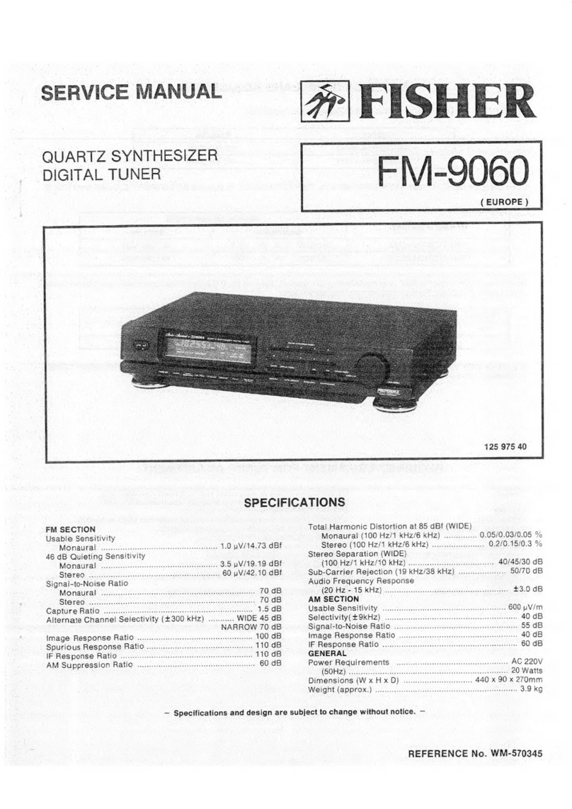
Fisher FM-120L User manual

ees
See
ee
Sees
Sees
Lee
oe
ets
ence:
BU
eee
Res
eat
eae
pz
ae
uy
ae
Pees
Oe
SERS
ESO
EES:
Se
SE
Se
Oe

CONTENTS
SHEGCITICAUIONS®
sc
cice
Goa.
ack
Bs
de
SBN
ee
ee
eS
ectiee
se
Wen
ee
aps
eee
we
ole
rea
ee
Be
2
Functional
Block:
Diagrant:
\<:sw.<
6s.
eae
deae
O
ESO
S
SEEK
ESS
WS
3
Dial
COrd
SteinGinG
0-5
osha
ea
area
Sw
ee
aw
ae
ad
SO
EE
a
ee
ale
Se
Ss
3
PMP
IC
EAI231:
Signal
Plow
}
2.
024
6060
66.0424
w
BRAT
EBS
EE
ES
re
ee
4
PM
MPxX-IC
LAS350
Signal
FlOW
34.0.5
cies
6
6d
baer
beware
bw
AES
4
AM-
RE
IE-IG:EA1240
Signal-FlOW.
6
veo
ad
ww
we
a
Soo
wa
whd
baa
e
en
dais
mak
4
AM-FM
Maltiplex
Alignment.
<4.
24.
6
vis
cred
5
Eh
RE
6
Geek
Wi
ae
AOE
5
Printed
Circuit
Board
(Bottom
View)
.........
0.0
cee
ee
ee
ee
ee
ee
es
6,7,8
Point
to
Point
Wiring
Diagram...
ee
ee
ee
eee
eee
9,10
Schematic
Diagram
.........
dasa
ep
inal
@
tin
te
he
fetes
oa
eos
th,
ea
os
ae
a
eee
11,12
Exploded
View
of
Cabinet
and
Chassis
..
0.1...
ee
ee
tees
13
Parts
eis.
ose
4k
ol
eon
Shae
an
Ee
OR
HE
Oto
BE
a
ee
a
ee
Oa
FM
Section
Tuning
Range
DIN
Sensitivity
(75
ohms)
(Mono)
(Stereo)
[HF
Sensitivity
(300
ohms)
(Mono)
(Stereo)
Stereo
Trigger
Sensitivity
Muting
Threshold
S/N
Ratio
(DIN)
(Mono)
(Stereo)
Selectivity
(DIN)
Capture
Ratio
AM
Suppression
Spurious
Rejection
IF
Rejection
Image
Rejection.
Sub-Carrier
Suppression
(19/38
kHz)
THD
(1
kHz)
(Mono)
(Stereo)
Frequency
Response
(20
Hz
—
15
kHz)
Channel
Separation
(1
kHz)
Output
Voltage
SPECIFICATIONS
87.5
—
108
MHz
1.5
2V
35
uV
3.0
nV
7.0
pV
3.0
uV
8.0
nV
65
dB
60
dB
72
dB
1.0
dB
60
dB
75
dB
80 dB
50
dB
70/76 dB
0.2%
0.5
%
+1.0
dB
40
dB
1V
MW
Section
Tuning
Range
Sensitivity
S/N
Ratio
Image
Rejection
Selectivity
(10
kHz)
THD
(30
%
Mod.)
Spurious
Rejection
IF
Rejection
LW
Section
Tuning
Range
Sensitivity
S/N
Ratio
Image
Rejection
Selectivity
(10
kHz)
THD
(30
%
Mod.)
Spurious
Rejection
IF
Rejection
General
Power
Requirements
Power
Consumption
Dimensions
(W)
x
(D)
x
(H)
Weight
(approx.)
520
—
1610
kHz
300
uV/m
55
dB
40
dB
40
dB
0.5%
60
dB
40
dB
145
—
355
kHz
500
uV/m
55
dB
40
dB
40
dB
0.5%
60
dB
40
dB
AC:
110/220
V,
50
Hz
16
W
400
x
220
x
125
mm
3.6
kg
—Specifications
are
subject
to
change
without
notice.—

FUNCTIONAL
BLOCK
DIAGRAM
FM
Antenna
FM
IF
IFET
2TR
3
Gang
V.C.
Quadrature
MPX
Ceramic
rae
ee
lee
,
Filter
El
A
eas
Hes
cages
9
rs
Fs
a
TS
Se
Tis
vol
|
Oat
Amplifier
FRONT
END
V
LW/MW
_—
Antenna
e
Low
Pass
Filter
Y
LEFT
/
2
Gang
V.C.
0.6
cietaas
‘
.
~~
| | |
\
ef
LW/MW
KL
7
:
MPX
Filter
Conv.
tS
.
\
|
.
|
LE.O.Signalinn.
\|
[MSR
29505)
\
i
=!
OS)
O)
|
Drive
TUNER
Amp.
ST
|
OUTPUT
IC
1@@@
|
NJM4558
ea
L.E.D.
Tuning
ND.
—
‘DIAL
CORD
STRINGING
-
10mm
ior
©
to
Q-
| .
61941
mm
a
Pra
POINTER
;
PULLEY
—
ener
PULLEY
S
~
PULLEY
S
©
Wee
~
is
Oo
psa
X
\
Koy
ay
52
vo
\d
3
TURNS
Za
@
DIAL
SHAFT
CORD
KNOTTING
NOTE:
Check
to
see
that
the
dial
cord
is
correctly
strung
|
by
turning
the
dial.
at
roe

:
Phase
Comparator
for
Lamp
:
Low
Pass
Filter
:
Phase
Comparator
for
VCO
:
Voltage
Controlled
Oscillator
:
Direct
coupled
Type
Flip-flop
FM
IF
IC
LA1231
SIGNAL
FLOW
Vee
+12V
COMPARISON
BIAS
VOLTAGE
AFC
_
TUNING
AFC.
TUNING
METER
La
a
eee
ee
ey
eee
ees
eee
ee
Co
METER
DRIVE
we
aR
CIRCUIT
7
s
IF
QUADRATURE
Bk
L1O00pA
NEUE
:
|
DETECTOR
P
6
pH
Auow
OUT
(TO
MULTIPLEX
IC)
§
MUTINGIN
AF
AMP
AF
MUTE
|
CONTROL
LEVEL
I
1
i
t
i]
I
|
{
i
|
{
DETECTOR
ond
LEVEL
DETECTOR
MUTING
SW.
a}
MUTING
SIGNAL
METER
MUT
DRIVE
t2
OUT
TO
FRONT
ORIVE
CIRCUIT
CIRCUIT
END
ro
CELAYED
bi
AGC
Se
ae
ecias
A
4
i4 16
200pA
13
(TO
MULTIPLEX
IC)
ax
TUNING
METER
Sy
O
OUT
PUT
SIGNAL
METER
FM
MPX
IC
LA3350
SIGNAL
FLOW
O)
OFF
COMPOSITE
SIGNAL
iN
PUT
PRE
AMP
F.F
TUFF
zo°
z30°
ee
IS9KH2Z
Poa
IS
KHZ
ed
(1)
INPUT
a
2)
7
MW
I
ANTENNA
(10)
(is)
i
SIGNAL
(/)
METER
IC
TOP
VIEW
6
15
1413
2
11
10
9
Vecorlev
OUTPUT
IC
TOP
VIEW

AM-FM
MULTIPLEX
ALIGNMENT
“AM
ALIGNMENT
For
alignment:
Maintain
generator
output
as
low
as
possible
for
suitable
indication.
i
Connection
.
Adjusting
Position
of
V.T.V.M.
circuit
Tuning
dial
Oscilloscope
Near
max.
capa-
rrT
iT
PIV
It
city
of
VC
at
AM
IFT
position
of
no
2-00040
interference
Connect
455
kHz
sweep
generator
to
VC4.
Connect
Oscilloscope
to
Test
Point
TP6.
a
REEehitune
ESE
120
\\2ee
Onn
tank
eee
eer
anns,ee
Connect
AM
generator
to
AM
BAR
ANT
EXT
AM
antenna
and
GND
acorn
9-25240
terminals.
Set
to
600
kHz.
.
MW
OSC
Modulate
with
30
%,
400
Hz.
Connect
Oscilloscope
and
.
9-20851
AC.
V.T.V.M.
to
Tuner
Output.
Change
frequency
to
1400
kHz.
1400
kHz
TC
01,03
Change
frequency
to
160
kHz.
LW
(RF)
160
kHz
Lw
OSC
9-20860
|
350
kHz
TC
02,04
1.
Variable
capacitor
completely
closed
4
Function
switch
to
“MW"
or
“LW”
2.
Set
the
dial
pointer
to
very
left
line
dial
scale.
5.
Use
a
screwdriver
with
plastic
grip
for
all
adjustments.
3
Connect
sweep
generator,
SG,
V.T.V.M.
and
oscilloscope.
Adjustment
FM
ALIGNMENT
|
|
|
FM
SFT
FM
QUAD-
;
Connect
Oscilloscope
to
Test
Point
TP4
RATURE
COIL
9-21320
V.T.V.M.
Oscilloscope
Position
of
Adjusting
Tuning
dial
circuit
Near
max.
capa-
city
of
VC.
at
position
of
no-
interference
Connect
sweep
10.7
MHz
generator
to
test
poin
VC2.
Connect
Oscilloscope
to
Test
Point
TP3
Quadrature
Detector
Connect
FM
RF
generator
through
two
120-ohm
resistors
to
FM
ANT
COIL
FM
antenna
screw
terminals.
9-21180
Set
generator
to
90
MHz,
FM
RF
COIL
modulate
with
400
Hz
to
provide
Connect
V.T.V.M.
9-20460
£75
kHz
deviation.
Set
generator
to
Tuner
Output.
EM
OSC
COIL
output
attenuator
as
low
as
9-20910
possible.
_
Change
generator
setting
to
106
MHz.
Repeat
adjustments.
106
MHz
1.
Variable
capacitor
completely
closed
_
4.
Function
switch
to
“FM”
|
2.
Set
the
dial
pointer
to
very
left
line
of
dial
scale.
5.
Use
a
screwdriver
with
plastic
grip
for
all
adjustments.
3
Connect
sweep
generator,
FM
SG,
V.T.V.M.
and
Adjustment
Adjust
VRO4
(5k-B)
so
that
frequency
counter
or
synchroscope
indicates
19
kHz.
Near
max.
capa-
city
of
VC.
at
position
of
no
interference
VROS
(1k-B)
1.
Variable
capacitor
completely
closed
|
3.
Function
switch
to
“FM”
2.
Connect
FM
stereo
SG
and
V.T.V.M.
4,
Use
a
screwdriver
with
plastic
grip
for
all
adjustments.
oscilloscope.
FM
ANT
input
impedance
is
75
ohm.
ALIGNMENT
: :
ee
: ;
-Connect
Frequency
None
.
FM
MPX
Position
of
Adjusting
Tuning
dial
circuit
counter
or
synchro-
scope
to
TP5
|
FO
(19
kHz)
Adjustmnet
Connect
V.T.V.M.
to
output
terminal
|
{R
Channel)
As
above
Steps
3,4
except
modulation.
Modulate
LEFT
channel
+67.5
kHz
—
400
Hz
audio
and
+7.5
kHz
—
19
kHz
pilot
carrier.
As
above
except
modulate
RIGHT
Channel.
FM
STEREO
Signal
Separation
Connect
V.T.V.M.
to
output
terminal
{L
Channel}.
Repeat
steps
1,2.
Set
at
position
with
max.
channel!
separation.
a
or

AM
ANTENNA
PC.BOARD
(BOTTOM
VIEW)
Pe
SH
Wee
eateyo
in
LED(POINTER)
PC.BOARD
_LED
(SIGNAL)
P.C.BOARD
(BOTTOM
VIEW)
(BOTTOM
VIEW)
Of
po3
poz
Lng
LN3i0
Bo
ial
MPX
FILTER
SW.
P.C.BOARD
(BOTTOM
VIEW)
:
rd
MD
&
Sh
Bes
that
fstaba
cS
eget
whan
te
ata
tatty
ae
ceombste
nate
MM
od
“useonet
ait
aru!
SERRA
ER
IF
BUTS
ERS
RA
SE
ty
RG
tata
i
Eat
tet
a
ec
erebe
te
NO
MEM
tes
ideo
atti
eee
ee
LJ
ae
MUTING
MPX
FILTER
SW
PUSH
2KEY

(BOTTOM
VIEW)
(BOTTOM
VIEW)
ee
isoTroM
VIEW)
RED.
MUTING
—
MPX
FILTER
SW
PUSH
2KEY

RF/IF,
MPX,
POWER
SUPPLY
P.C.BOARE
(BOTTOM
VI
EW)
ANT.
TERMINAL
eae
rer
aL
o)
si
pel
Lz
‘SSRaPO
nin
nna
Mets
ammeter
cmrE
i
ou
—
——
=
Ll
Lo
a
:
Ls
Lw
MW
FM
MONO
FM
AUTO
1.
VRO1
Muting
Level
Adjustment
|
:
_
3.
VRO3
S-Curve
Center
|
Aciuaunent
|
Adjust
VRO1
at
the
antenna
input
of
FM
75
ohm
and
the
sensitivity
of
Bey
(Muting
Switch:
ON)
until
the
v
wave
lon
:
Connect
DC
voltmeter
between
Test
Point
No.1
and
Test
Point
No.2
at
no-signal.
Then,
adjust
VROS
until
O
V
Is
obtained.
amplitude
of
the
tuner
output
becomes
half.
:
:
; —
4.
VRO6
Tuning
Indicator
Adjustment
:
2.
VRO2
Signal
Indicator
Adjustment
-
ee
Connect
the
DC
voltmeter
to
Test
Point
No.
7
and
adjust
VRO6
until
the
voltage
becomes
0£50
mV.
Adjust
the
attenuator
of
FM
SSG
to
60
dB
and
VRO2Z
until
the
final
LED
of
the
Signal
Indi
cator
$
slightly
lights
up.
7

Ve
.
POINT
TO
POINT
AC
SELECTOR
©
|
HOV
ee
:
AM
BAR
ANT.
PC.B.ASS’Y
©
FM
ANTENNA
nen
1310-4001-0492
|
752
TERMINAL
TUNER
OUTPUT
220V
preeeseeasy
adhe
reborn
rac
scenNtta
sy
seisksnn
ii
fahiacoped
snorted
PERSO
REISE
B
1
cs
e,
:
‘
a
see
eae
erate
SO
nt
aR
eae
ones
ES
HOSEN:
s
He
é
.:
eee
5
ts
‘
:
De
y
anaes
iieinkeniioaiedt
et
Fe
ad
nN
ans
Se,
seein
aerate
Doan
sisi
ba
K
Totes
Sona.
Otani
Pauancoaes
ION
<
poremasnenncsay
saan
Tesoaaseisteasenags
See
3
©
i
:
Pe
im
ee
&
ve
sigh
"4
i
A
ee
siesegaceineiat
: :
be
pt
fentaia
ss
Bee
:
ee
Nee
te
rr
rerercktnens
Aaa
ait
pe
ee
Varese
Ee
So
Bue
*
Epis
ie
Bor
a
:
sepa:
Sapo
re
: 2
ee
P :
cay
:
é
Oe
es
ae
-
ue
:
‘ : 4 3
ae
eS
sie
Be
pth
eae
3
REE
bi
?
Sa
HAE
Ta
RAR
,
;
oe
pesca
é 5
i
: :
ets
5
Rprctensss
46,
a
i
RE
x
Lm
ie
: é
G8
f :
;
:
ee
: é
yee
my
A
mS
anes
omen
ca
ae
.
a
renin
_
3 : $ x “
i
3 s ‘
ve
s
2
Pp
i
i
&
oe
Bs
BRAN
Bi
ae
My
sS
i
ge
ONE
:
:
ee
‘
NES
:
ee
:
Se
oe
BES
Bs
Se
pe
Bi
NS
Bite
gy!
si
4
rg
meres
$5
cae
omy
> >
‘.
2
os
:
ny
i,
y
a
i 4 ¥
4 5
7 é E :
iy
‘ i
t
‘
oe
é
Be
ee
a
5
ae
eit
es
S 7 3
ie
ee
Ro
ee
Ri
RR
‘
%
Ne
i
ews
Ae
we
: :
Bees
is
Re
ay
et
Os
sehen,
eee
Scan
ee
‘
:
Bh
Se
ids
is
x
eee
oo
ie
gai
es
a
‘3
ae
Ee
o
*
Oe
ns
sacenaontet
he
3
s ;
ane
:
me
Pe
ea
tee,
ee
Bass
ay
ee
aie
COACH
a
Rese
deen
aed
; ; : ; i
%
eee
Ss
pits
D
\
2
Boe
SOE
EIN
glee
cae
ieee
eS
aesnonseoniaal
Ma,
SEA
at
:
:
pa
:
oe
TAY
ee
aan
oe
ft
;
:
%
f
ss
Su
SSS
:
i
superar
samen
ee
one
hy
ten
aon
on
Sesser
:
BEE
G
f
ve
3
ts
EE
Sams
Sapape
se
aatadgs
canine
igen
etary
a
npniaerte
oat
sai
TAN
saan
se
BEC
a
aaa
nn
Conia
SUS
SE
SSS
SSE
GAN
IMMORAL
RGAE
EISELE
AOS
ESSE
EYL
LORDS
SII
ERLINDA
NIRA
ERE
ILLES
EES
ANERENT,
ROIS
oe
a
BiaaRinresn
ase
:
BNNs
ae
ye
R
2
era
‘
a
‘
go
5
Cy
Aaa
Lo
gee
apd
eens
OLE
Cea
ees
SLURS
TESOL
REE
SRS
RCH
“
we
z
‘ ‘ i e
oe
psyche
Bite
Seat
are
aay
pkgs
Re
PES
RO
ee
iene
sagas
corneas
POR:
ag:
ON
Be
a
aS
cee
at
ra
EERE
ERRNO
tp
PRO
CRETE
MONO
MW
|
a
ee
SR
RDS
eae
oo.
EM
mex
LE
DO
(PCINTERJP
C8
_
MUTING
FILTER
|
STERED
IND.
|
ASS'Y
FM
MUTING
MPX
FILTER
P
7
AL
LAMP.
8Vv,
30OmAx3
:
L.ED.
(SIGNAL)
P
C.
oe
| —
1310-4001-0493)
|
6V,
30mA
1310-4001-05500
©
1310-400
1-0490
|
-—10—

SCHEMATIC
DIAGRAM
RF
COIL
R40
68
1/2
W
|
68
9-
acdeorce
15P_
/
—~¢
R44
$=
SBKHz
WV:
c24
+|
R34
e320
At
S53
Se
ANT.
COIL
ios
0.0471
C25
‘yy
22
1/2W
100/4g
aoe
+f
ANT.
TERMINAL
ios
ee
ev
:
a.
AZOV]
:
0,
Pasa
9-21350
(9-21320)
OB
MAS
TE:
»
e—
Il
R37
3.3K
pero.
:
R25
mall
R25
ne
5.6K
St
2.2K
7
R18
>
II
eh
330
se
Sa
:
gees
OTP!
yros
S-CURVE
;
Hs
R27
—
Ree
200K-
-p
CENTER
C49
ro
|
IT
oe
C18
8.2K
ADJUST
22/50
ae
oe
:
120K
ra
\
C19
|
>
RSS
R13
0047
ae
a
Spe
100
27
330P
,
0.47
|
—
O
OSC
COIL
C10
9-
oe
7PCH
ev
FM
SEPARATIO
CONTROL
R59
a
C53
R302
C29
ii
100°."
IOOM6
56K
3
47/251-
R33.
‘OK
FREE
RUN
FREQ.
CONTROL
|
R136
270/1W
—|
C95
CiO0O
1000/25
100/16
ae
R1i37
470
DOG.
pia
asses
gu
ar
ied
gle
a
cs
a
ttm
bene
aeons
ovens
ecoomete
as
ius
oso
sored
Daamabeicias
orton
i
ape
R120
R122
Ri24
|
|
560
470
390
Sto
[O.0ev]
|
22
923
R95
560
a
[O88V
|
oe
C86
I
|
ee
|
|
Li
|
[|
228
(450mv]
|
|
|
D24
R106
Q15
|
[|
pea
820K
ria
|
vr)
|
|
|
:
|
H
\aa/
i
i
i
RiOS
TE
Lt
|
|
470K
tr
raed
|
Le
|
Le
R97
ROB
|
|
20O0mvV.
|
|
|
4.7K
470K
A
RNS
SRG
Ag
|
|
|
oe
3.3K
$
i0K
O
OG
GREEN
|
HH
|
|
03
RG
RO6.
|
|
3330.
R99
|
ark:
:
e
:
:
R100
|R101
R102.
eis
E
150K
{10K
470K
‘Seinen
nae
OF
|
FM
AUTO
[FM
MONO
_7138
Tek
FUNCTION
SW.
PUSH
4
KEY
NOTES:
1.
All
resistors
values
are
indicated
in
‘‘ohm’
(K=10?
,M=10°).
bb.
All
voltages
+10%
with
respect
chassis
ground
2.
All
capacitors
values
are
indicated
in
‘uF’
(P=107'7).
c.
No
signals
at
input
terminals
3.
All
voltages
indicated
onthe
scirematics
are
measured
under
the
d.
AC
input
at
220
volts
50
Hz
following
conditions.
.
se
4.
This
is
a
fundamental
schematics
diagram.
Some
products
may
a.
UseaV.T.V.M.
8
: |
_
|
be
modified
without
notice.
—11—
Ce
_
|.
:
|
_12-
Soo
tesa
sage
aces
2-00080
|
STEREO
|
IND.
6V,
30mA
oe
2°00070
ISKHz
R55
3.3K
:
|
|
R135
270
1/2W
|
|
eal
poe
15.5V
19.0V
R130
100/41W
ae
ae
ee
R133
Tee
'
(RES
C60.
a
en
ees
el
Hel
EN
oe
|
:
39
1/2Wi
Cerf
FUSE
(3)
av]
fesoxs
47K
As
le
:
et)
Riz]
|
C94
7
r?
:
ra
aene
eta
i
coe
ue
|
iene
RIS?
220+
lO0o/
~
1D03
|DO4
TesOms
Je
Fav]
a
Lh
220/
of
|
HSN)
100
Fvaw!
ay
-
+
2
|
Z
7
coenenae
ri
>!
foned
ee
ee
3.3K
R134
£
coz
+
v2
coe
Ico2;}
i
ob
TT
peep
Fuse
DIALLAMP
eee
[220
7
ae
a7O
0.011
F
°
poop
S
oO-
i
:
fee
eo
Ff
|
|
pee
or
/25
WF
Of
mre
is
i
110/220V
AC
50Hz

EXPLODED
VIEW
OF
CABINET
AND
CHASSIS
—
=
43
=
PACKING
PARTS
LIST
Ref.
No.
Parts
Number
—
131
6
1139
85602
131
6
2119
02131
131
6
3009
30371
131
6
3009
30372
Description
Box
Corrugate-E
XP
Bag
Polyethylene-E
XP
Pad
(Right)
Pad
(Left)
ACCESSORIES
PARTS
LIST
Ref.
No.
Parts
Number
4
2442
00030
131
6
4119
84902
131
6
4519
15700
CABINET
PARTS
LIST
Ref.
No.
Parts
Number
PBRWN>
131
2
1105
25300
131
2
1410
23700
131
2
1801
14600
131
2
3101
71200
Description
Antenna
FM
Explanatory
Booklet
Guarantee
Certificate
Description
Plate
Bottom
Cover
(Top
Cover)
Leg
Metal
Mount
(Cover)
APPEARANCE
PARTS
LIST
Ref.
No.
Parts
Number
131
0
1016
36901
131
2
1202
17800
131
2
1203
50601
131
26113
37800
131
26113
38900
131
2
1116
19101
131
2
1201
35901
131
2
1205
24900
131
2
1601
64500
131
2
1601
64600
131
2
1601
66400
131
2
2307
11300
131
2
5205
24000
Description
Panel
Decorate
Assy
Escutcheon
Dial
Panel
Control
Shelter
(Push
Knob)
Shelter
(Push
Knob)
Frame
Plate
Dial
Decorate
Plate
Dial
Knob
(Power
Switch)
Knob
(Push)
Knob
(Tuning)
Slide
Cushion
PARTS
LIST
CHASSIS
PARTS
LIST
Ref.
No.
Parts
Number
131
0
3002
11300
131
0
3003
21200
131
0
3020
11000
131
0
3020
11800
131
2
1102
47209
131
23101
70800
131
23101
70900
131
23101
71100
131
23110
00300
131
2
3304
17600
131
2
3305
30000
131
2
4106
23400
131
2
4111
00400
131
2
4112
10400
131
2
4120
13100
131
2
4220
10502
131
2
4221
00600
131
26110
29301
131
26111
14200
131
2
7104
00500
Description
Drum
Assy
Shaft
Dial
Assy
Pulley
Assy
Pulley
Assy
Rear
Cover
Metal
Mount
(AC
Cord)
Metal
Mount
(Antenna)
Metal
Mount
(Panel
Front)
Plate
Pad
Wire
Plate
Dial
Rear
Panel
Front
Metal
Mount
Pulley
Spring
Rope
Dial
Rope
Slide
Rail
Pointer
Ring
Snap
‘Rivet
Shelter
Light
Bushing
(Output
&
Line
Cord)
Plate
Pad
Switch
'
ELECTRICAL
PARTS
LIST
Ref.
No.
Parts
Number
—~14—
*
*£ *&
*
4
2312
01020
4
2312
04520
4
2352
00110
4
2432
00140
4
2512
12320
4
6122
00440
46129
20771
4
6129
20777
4
6129
20779
131
0
4004
15101
131
0
4001
04896
131.0
4001
04921
131
0
4001
04901
131
0
4001
04931
131
0
4001
05500
C2EHRM103A
Description
Slide
Switch
Push
Switch
Power
Socket
1P
(FM
AM
Ant.)
Power
Cord
Power
Transformer
Pilot
Lamp
6
V,
30
mA
(Stereo)
Dial
Lamp
8
V,
300
mA
Dial
Lamp
8
V,
300
mA
Dial
Lamp
8
V,
300
mA
Wire
Shield
Assy
RF/IF,
MPX,
Power
P.C.B.
Assy
AM
Antenna
P.C.B.
Assy
Muting/MPX
Filter
P.C.B.
Assy
L.E.D.
(Signal)
P.C.B.
Assy
L.E.D.
(Pointer)
P.C.B.
Assy
Metallized
Paper
0.01
uF
250V
+20%
*_Not
aservice
part.

PARTS
LIST
(Continued)
PARTS
LIST
(Continued)
RF/IF,
MPX,
Power
P
.C.B.
Assy
131
0
4001
04896
ed
Ref.
No.
Parts
Number
Description
Ref.
No.
Parts
Number
Description
Ref.
No.
PartsNumber
Description
Ref.
No.
Parts
Number
Description
4
ei
ae
ales
Sue
ad
CAPACITORS
SEMICONDUCTORS
RESISTORS
4
eramic
Filter
1Q.
Zz
;
5
ee
a
C26
CIHYYZ473APA
Ceramic
0.047
uF
50V
+80,—20%
D01,02
DGG-1N4002
—_
Diode,
1N4002
or
DS-135
R25
R2EDZJ562APA
Carbon
5.6k
1/4W
+5%
W515
GAO.
Swiss
Puch
Akey
C27
CIHCSK331SL_
Ceramic
330pF
50V
£10%
03,04
|
R26
RIEDZJ222APA
Carbon
22k
1/4W
45%
nie
mele
at?
C28
CIHRY-474APA
Electrolytic
0.474F
50V
DOS
DNN-RD16E
Zenner
Diode,
RD16E
R27
R2EDZJ822APA
Carbon
8.2k
1/4W
+5%
4
2329
y
=
|
7
j
Sab
0000
Fuss
FOO
9
C1ERE-475A
Electrolytic
4.7
mF
26V
DO6
DNN-RD9.1E
Diode,
RD9.1E
R28
RIEDZJ124APA
Carbon
120k.
1/4W
+5%
1
9340
0880
Fuss
T3154
C30
CIHYYZ473APA
Ceramic
0.047
uF
50V
+80,—20%
DO7,08
205
5
9040
44210
Diode,
DS-442
R30
RIEDZIS63APA
Carbon
56k
1/4W
+5%
42352
00200
Fuse
Clip
a
See
a
ei
sana
1uF
50V
09,11
|
R31
R2EDZJ103APA
Carbon
10k
1/4W
+5%
1
2362
00370
Plug
6P
-10
lectrolytic
100uF
16V
12,13
R32
R2EDZJ473APA
Carbon
47k
1/4W
+5%
|
C33
C1CUBX474A
Sint.
Alu.0.47nF
46V
+40,~—20%
14,15
R33
ROEDZJO29APA
C
(eo
4
2372
00770
Antenna
Terminal
,
. |
arbon
2.2k
1/4W
+5%
4
2372
00830
CE
Terminal
1P
C34
CICUBX224A
—
Sint.
Alu.0.22uF
16V
+40,—20%
16,17
,
R34
R2HXBJ220A
=
Oxide
Metal
Film
22
1/2W
+5%
eS
a
CL
TOR
C35
CICUBX474A
Sint.
Alu.0.47F
16V
+40,-20%
D19
DNN-RD5.6E
Zener
Diode,
RD5.6E
R37
R2EDZJ332APA
Carbon
3.3k
1/4W
+5%
|
C36
C1IERY-475APA
Electrolytic
4.7
uF
25V
D20,21
20559040
44210
Diode,
DS-442
R38
R2EDZJ822
+59
eo
Oe
C37.
CIHFYK473APA
Mylar
0.047uF
50V
#10%
D22.
DNN-RD9.1E
Diode,
RD9.1E
R39
«ROEDZIZ22APA
Carbon
22k
1/AW
28%
4
2562
00040
IF
Transformer
AM
a
:
|
Acari
arbon
;
1/AW
=+5%
Foe
an
ote
caer
ed
oe
CHEE
Styrol
1500pF
50V
38%
D24
205
5
9040
44210
Diode,
DS-442
R40
R2HXBJG80A
Oxide
Metal
Film
68
1/2W
+5%
42569
21360
IF
Transformer
FM
C3940
CIHFRMI03A
Mylar
=
0.01
uF
SOV
220%
ICO1
=:
206.
5
0161
23151
IC,
LA1231NS
R41.42
R2EDZJ562APA
Carbon
5.6k
1/4W
+5%
ei
EG
C4142
CIHRY-474LPA
Electrolytic
0.474F
50V
ICO2
206.
5
0743
35012
IC,
LA3350
R43,44
R2EDZJ274APA
Carbon
270k
1/4W
+5%
eo
oe
i
C49,50
CIHRY-225LPA
Electrolytic
224F
50V
ICO3.
+
206
5
0171
24010
IC,
LA1240
R45,46
R2EDZJ473APA
Carbon
47k
1/4W
+5%
Foe
co
a0nea.
Osc
Corry
C5152
CIHFYK332APA
Mylar
0.0033
uF
50V
+10%
C04
ss
WWJ-NJM4558DX
IC,
NJM4558D
R51,52
R2EDZJ332APA
Carbon
3.3k
1/4W
45%
{ao
amr
8
Gol
Fl
S.
Senthil
i.
cee
aeee
Rout
RIEDELTIAPA
Gabon
470
i
5%
eramic
O.
Me
+80,—20%
-
-
R
2$C535
B,
C
R55,56
R2EDZJ332APA
Carbon
3.3k
1/4W
+£5%
4
2599
20300
Balun
57
Q03.04
203
5
5500
9304
;
6
,
O
TR
2SC930
D,
E
R57,58
R2EDZJ102APA
Carbon
1k
1/4W
+5%
:
peek
ah
a
iy
aches
C59.
CIHCYK220APA
Ceramic
22pF
50V
410%
Q06,07
2035525157160
TR
2SC1571
F,G
R5Q
BOUMBITOIA.
cOxdde
Mista
Ein
1004
Wa
5%
os
er
a
0daG
ie
oncita:
ae
C60,61
CIHYYZ473APA
Ceramic
0.047
nF
50V
+80,—20%
Q08,09
2035651004160
TR
2SK41
F
R60
RIEDZJIO3APA
Carbon
10k
1/4W
+5%
! 7
C62
CIHFYK103APA
Mylar
0.01nF
5OV
+10%
Q10,11
2035500053660
TR
2SC536
F,G
R61
ROEDZJISSAPA
Carbon
1.5M
1/4W
+5%
lise
eres
sei
Lae
seein
ee
C63
CIHCYK331APA
Ceramic
330pF
SOV
210%
12,13
R62
R2EDZJ824APA
Carbon
820k
1/4W
+5%
ae
eee
eae
aoe
ah
C64.
CIHYYZ102APA
Ceramic
0.001
uF
50V
+80,—20%
14
R63.
-«~
R2EDZJ472APA
Carbon
4.7k
1/4W
+5%
wees
45598
61010.
VE
poe
GI
ee
:
eee
C65
CIHFYK103APA
Mylar
0.01
HF
50V
+10%
Q15
2035525157180
TR
2SC1571H
R64
R2EDZJ222APA
Carbon
2.2k
1/4
+5%
vane
4
5959
01000
AIRO00LE
ae
ies
Dina
£0
CIHYYZ102APA
Ceramic
0.001
nF
50V
+80,—20%
Q16
2035500053660
TR
2SC536
F,
G
R65
RIEDZIIO2ZAPA
Carbon
1k
1/4W
+5%
ag:
i
559
61000.
S/R
GE
[Feo
Bud
EF
ae
C67
CIHFYK103APA
Mylar
0.01
nF
50V
+10%
Q17
20357230
60860
TR
2SA608
F,
G
R66
RIEDZIIOIAPA
Carbon
100
1/4W
+5%
GEE
4
9559.
00000:
VR
1kB(EM
ay
aan
C68
CIHCYK470APA
Ceramic
47pF
50V
+10%
Q18,19
20355000
53660
TR
2SC536
F,
G
R67
ROEDZJ155APA
Carbon
1.5M
1/4W
45%
ie
4
S595
00060.
NIRAGOK
8
fruning
(nd.
Adjust)
C69
CIHYYZ473APA
Ceramic
0.047
uF
50V
+80,—20%
20,21
R68
ROEDZIS24APA
Carbon
820k
1/4W
+5%
a
5e55
50400.
Chaka
CoD
Oue
C70
CIERY-106APA
Electrolytic
104F
25V
Q22
2035671117570
TR
2SC1175G
R69
R2EDZJ472APA
Carbon
4.7k
1/4W
+5%
a
Aas
Del
Ig
AE
tice
Tak
C71
CIHFRM103A
Mylar
(0.01
uF
SOV
20%
023,24
2035500053660
TR
2SC536
F,G
R70,71
R2EDZJ102APA
Carbon
1k
1/4W
+5%
ee
Foes
en
ane
cake
Cen
C72
CIHYYZ473APA
Ceramic
0.047
uF
50V
+80,~—20%
25,26
R79
RIEDZI331APA
Carbon
330
1/4W
15%
104
4.2539
20410
Choke
Coil
470
nH
—
C73
C1THRY-105APA
Electrolytic
1uwF
50V
Q27
203
5
8620
32550
TR
2SD325E,F
R73
RIEDZJ222APA
Carbon
2.2k
1/4W
+5%
|
C74
C1ERY-475APA
Electrolytic
4.74F
25V
R74.
R2EDZJ152APA
Carbon
1.5k
1/4W
+5%
CAPACITORS
ae
rte
ce
oe
sy
ae
RESISTORS
R75
R2EDZJ153APA
Carbon
15k
1/4W
+5%
:
|
ar
M
£10%
|
R7
H
+59
Cols
CIHCYK150APA
Ceramic
15pF
50V
#10%
C77.
~~
CIHFRM683A_—s
Mylar_:-«0.068uF
50V
+20%
ee
eee
ee
a
ee
C0203
CIHYYZ223APA
Ceramic
0.022uF
50V
+80,-20%
C78
CIHRY-105APA
Electrolytic
1”F
50V
Ge
ee
SE
aie
*
7879
R2EDZJI03APA
Carbon
10k
1/4W
#5%
Cos
C1HCYK1S50APA
Ceramic
15pF
50V
+10%
C79
—-CICRE-107A_—
Electrolytic
100uF
16V
OO
arbon
4.7K
WW
28%
880
REDZJ272APA
aes
,
eb
;
QEDZJ223APA
Carbon
22k
1/4W
+5%
Carbon
2.7k
1/4W
+5%
C05
CIHCYD1O0APA
Ceramic
10pF
50V
+0.5%
C80
CIHFYK682APA
Mylar
0.0068uF
50V
+10%
ne
:
©
pa]
Sec
ERP
he
Gacce,
Geo
-
aaa
eee
COB
CIHYYZ223APA
Ceramic
0.022uF
50V
+80,-20%
C81
§
CIHSEJ341A
—Styrol_
|
S40
pF
SOV
26%
ee
Ha
ye
eee
eee
ee ak
ee
CO7
CIHCYK101APA
Ceramic
100pF
SOV
+10%
C82
CIHCYCOSOAPA
Ceramic
B5pF
5OV
+0.25%
RO
R
sale
Mi
is
R83
RIEDZJZ32APA
Carb
3k
1/4
=)
CoB
«Ss
CIHCYCO30APA
Ceramic
3pF
50V
#0.25%
C83
—-
CIHSEJ151A_~—Styrol
«=
150
pF
50V
+5%
Be
ee
a
eee
ae
cee
Res
©
ROEDZIISD
PA.
Caton
fe.
4a
cog
CIHCDK270PH
Ceramic
27pF
50V
+10%
C84
CIHCYK560APA'
Ceramic
56pF
50V
+10%
R10
RIEDZIIO3APA
a
lok
1/aw
5%
«RSS
R2EDZJ104APA
Carbon
100k
1/4W
15%
.
’
0
7
‘
;
+t
Tr
omg
|
R13
R2HXBJ101A
Oxide
Metal
Film
100
1/2w
+5%
88
R2HXBJ680A
=
Oxide
Metal
Film
681/2W
+5%
Cia
CIHVYZ2ZBAPA
Guam
OO2zHF
SOV
10-20%
O89
CIEREATEA
Eevoiis,
47aF
26V,
ig
—RZEDZIQTAPA
Carbon”
900"
/4H|
a8
RED
RAEDZIIQ2APA
Carbon
Nk
1/0
35%
ce
1
eramic
VU.
K
'
©
pa
PE
VICGCAPA
-
oa
rena!
a
‘oat
0
R15
RIEDZJ222APA
Carbon
22k
1/4w
+5%
R90
R2EDZJ273APA
Carbon
27k
1/4W
+5%
;
:
ee
PR
ie
se
.
ae
i
;
Bea
0
R16
R2EDZJ471APA
Carbon
470
1/4w
+5%
R91
R2EDZJ473APA
Carbon
47k
i1/4W
+5%
18,1
:
sd
ne
ica
Co
R17
R2EDZJ122APA
Carbon
1.2k
1/4W
+5%
R92
R2EDZJ103APA
Carbon
10k
1/4W
+5%
C20
CIHYYZ223APA
Ceramic
0.022
uF
50V
+80,-20%
C9495
C1ERE-108A
Electrolytic
1000
nF
25V
aie
MOEDIIGSTAPA.
Gabon
330
aw
45%
93.94
R2EDZJIO2APA
Carbon
1k
1/4W
#5%
C21
CIHRY-105APA
Electrolytic
TuF
50V
C96
CI1ERE-477A
Electrolytic
470
uF
25V
R19
RIEDZJIO4APA
Carbon
100k
1/4W
ats
R95
ROEDZJS61APA
Carbon
560
1/4W
+5%
C22
C1HRE-105A
__
Electrolytic
uF
50V
C97,98
C1ERE-227A
Electrolytic
220uF
25V
R20
R2EDZI222APA
cea
(OG
R2EDZJ331APA
Carb
30
1/4W
+5%
:
Carbon
2.2k
1/4W
+5%
arbon
3
+5%
C23
CIHYYZ223APA
Ceramic
0.022F
50V
+80,-20%
C99
C1IERY-106APA
Electrolytic
10uF
25V
R21
BSED
ZIATAAPA.-C
RO7
RIEDZJA72APA
C
kK
1/4
;
;
arbon
470k
1/4W
+5%
| :
arbon
4.7
W
45%
C24
CIHYYZ473APA
Ceramic
0.047
nF
5OV
+80,-20%
C100
CICRE-107A
Electrolytic
100unF
16V
R98
SEDZJAT
|
d
Ai6S..
“CINCY
KATOADA:-Covac
:
ore
R22
R2EDZJ223APA
Carbon
22k
1/4W
+5%
R
4APA
Carbon
470k
1/4W
+5%
C25
CICRY-4A76APA
Electrolytic
47u4F
16V
eramic
47pF
50V
+10%
R23
RIEDZJ103APA
Carbon
10k
1/4W
+5%
ROO
RIEDZJ473APA
Carbon
47k
1/4W
+5%

|
Ref.
No.
Parts
Number
~
R100
R101
R102
~R103
R105
R106
RESISTORS
R2ZEDZJ154APA
—
R2EDZJ103APA
|
R2EDZJ474APA
R2EDZJ102APA
~R2EDZJ474APA
~
R2EDZJ824APA
R107,108
RZEDZJ103APA
R111,112
R2EDZJ332APA
R113,114
RZEDZJ821APA
R115
R116
R117
R119
R120
R121
R122
R123
R124
R125
R126
R127
R128
R129
R130
R131
R132
R133
R134
R135
R136
R137
R138
R139
R140
R143
R2EDZJ332APA
~
R2ZEDZJ103APA
R2EDZJ472APA
R2EDZJ331APA
R2EDZJ561APA
R2EDZJ103APA
R2EDZJ471APA
R2EDZJ103APA
R2EDZJ391APA
R2EDZJ103APA
R2EDZJ331APA
R2EDZJ103APA
R2EDZJ271APA
R2EDZJ103APA
R3AXBJ101A
R2HXBJ221A
R2HXBJ101A.
R2HZPK390A
R2HXBJ151A
R2HXBJ271A
R3AXBJ271A
R2EDZJ471APA
R2EDZJ184APA
R2EDZJ103APA
R2HCPK222A
R2EDZJG82APA
Description
|
Carbon
150k
Carbon
10k
Carbon
4/0k
Carbon
1k
Carbon
470k
Carbon
820k
Carbon
10k
Carbon
=
3.3k
Carbon
820
Carbon
3.3k
Carbon
10k
Carbon
4.7k
Carbon
330
Carbon
560
Carbon
10k
Carbon
470
Carbon
10k
Carbon
390
Carbon
10k
Carbon
330
Carbon
10k
Carbon
270
Carbon
10k
PARTS
LIST
(Continued)
AM
ANTENNA
P.C.B.
Assy
131
0
4001
04921
1/4W
1/4W
1/4W
1/4W
1/4W
1/4W
1/4W
1/4W
1/4W
1/4W
1/4W
1/4W
1/4W
1/4W
1/4W
1/4W
1/4W
1/4W
1/4W
1/4W
1/4W
1/4W
1/4W
Oxide
Metal
Film
100
Fuse
39
1/2W
IW
+5%
Oxide
Metal
Film
220
1/2W
+5%
Oxide
Metal
Film
100
1/2W
+5%
Ref.
No.
Parts
Number
45%
45%
+5%
+5%
15%
45%
+5%
£5%
45%
45%
¢Q]
45%
15%
£5%
sey,
ROT
45%
+5%
Ref.
No.
Parts
Number
Description
|
4
2579
25240
Bar
Antenna
AM
MUTING,
MPX
FILTER
P.C.B.
Assy
131
0
4001
04901
Description
4
2312
04550
Switch
Push
2key
CAPACITORS
C1IHFYK103APA
Mylar
RESISTORS
R2ZEDZJ222APA
Carbon
2.2k
1/4W
45%
L.E.D.
(SIGNAL)
P.C.B.
Assy
+5%
1310400104931
+5%
+5%
Ref.
No.
Parts
Number
+5%
+5%
+5%
03,04
+10%
sae
Oxide
Metal
Film
150
1/2W
+5%
Oxide
Metal
Film
270
1/2W
+5%
Oxide
Metal
Film
270
Carbon
Carbon
Carbon
Solid
Carbon
470
180k
10k
2.2K
6.8k
1/4W
1/4W
1/4W
1/2W
1/4W
TW
£5%
£5%
t5%
£50
Ref.
No.
+10%
+5%
DO1,02
DO3
=
Description
131
0
4006
22241
Cord
Assy
SEMICONDUCTORS
DO1,02
DYY-SLR-54GG
_L.E.D.
SLR-
o4GG
(Green)
L.E.D.
(POINTER)
P.C.B.
Assy
131
0
4001
05500
Parts
Number
Description
131
0
3011
19400
Pointer
Assy
131
21110
28800
Plate
Decorate
131
2
3701
28000
Mount
Electric
Part
131
0
4006
24201
Cord
Assy
SEMICONDUCTORS
DWW-LN210RP
L.E.D.
LN210RP
(Red)
DWW-LN310GP
—_L.E.D.
LN310GP
(Green)
0.01
uF
50V
£10%
+5%
FISHER
Service/E
rsatzteillager:
FISHER
HiFi
Europa
Vertriebs-GmbH
SchénstraBe
80,
D-8000
Miinchen
90
—
Telefon
089/2379-1
Telex
5-212384
D
Wenden
Sie
sich
bitte
mit
technischen
Fragen
und
Ersatzteilbestellungen
an
diese
Adresse.
Verwaltung,
Verkauf
und
Ausiieferungslager:
FISHER
HiFi
Europa
Vertriebs-GmbH
TruderingerstraRe
13,8000
Miinchen
80
-
Telefon
089/2379-1,
Telex
5-24665
D
PRINTED
IN
JAPAN
80/June
WM-5087
Table of contents
Other Fisher Tuner manuals