Stockcorner JC-5s User manual

1
JC-5s
4KW PEP , 1KW RMS AUTO ANTENNA COUPLER
1) DIRECTLY CONTROLLED BY ICOM, ALINCO & KENWOOD.
2) INDEPENDENT CAPACITOR INPUT AND OUTPUT BLOCKS!
3) 3 mm COIL WIRE & INTERNAL FAN FOR THE BIG COILS!
4) DIPPED SILVER MICA CAPACITORS ON THE INPUT CIRCUIT
5) CERAMIC DOORKNOB CAPACITORS (7.5 KV) ON THE OUTPUT!
6) 10 VACUUM RELAYS (8 ΚV)&19 SCHRACK RELAYS.
7) 4ΚW SSB, CW (EXCEPT λ/2 ANTENNAS)
8) "TUNED" START UP AT THE LAST USED FREQUENCY!
9) 50 MEMORY POSITIONS - NO INTERNAL BATTERY!
10) PROTECTION FROM STATIC DISCHARGE WHILE OPERATING!
11) INTERNAL 12 V- 1.6 A FUSE.
12) A TO D SWR CONVERSION FOR HIGHER TUNING ACCURACY!
WHEN A SEPARATE POWER SUPPLY IS USED FOR THE COUPLER, WE
MUST CONNECT THE ( –) TERMINAL OF THE SUPPLY TO THE CHASSIS
OF THE USED TRANSCEIVER TO CLOSE THE RETURN 12 V PATH VIA
THE SHIELD OF THE COAXIAL CABLE.
1. BROWN (1)
OPERATING VOLTAGE
+12V
2. GREY (2)
TUNE COMMAND TO COUPLER
START
3. YELLOW (3)
TX COMMAND TO TRANSCEIVER
KEY
4. BLACK (4)
0V MEM OFF , +12V MEM ON
MEM CONTROL

2
A FEW WORDS ABOUT JC-5s
JC-5 was designed to cover the needs of high power professional use and increased
reliability. So, materials of the best in market were used, despite the high cost of some of
them, due to their limited production! At the pictures you can take a look at the inside of
the coupler. In the photos we can see mounted in a row the vacuum relays, by which the high
voltage doorknob ceramic capacitors are selected. We can also see the high voltage copper
wiring above the p.c. board. The reason we did not construct the high voltage paths on the
board is that we don’t consider the p.c. board reliable enough for withstanding voltages of
the order of 8 KV that may appear at the output of the coupler when λ/2 or short vertical
antennas are used!
TUNING PROCEDURE WITH THE CONTROL BOX
We set the switch of the control box to the M position if we intend to use memories or to the O
position, if not. We set the transceiver to AM, FM, CW or RTTY mode with the output power
adjusted in the range 10 –20 W. We push the PTT and keep it pushed. We push the button until the
LED is lit. We wait until the LED goes off and then we stop transmitting. If the LED quickly turns on
and off at the end of the tuning procedure, the tuning procedure has failed and the coupler goes
THROUGH. Starting up the coupler, if the switch is at the M position, it recalls the last used
memorized frequency, otherwise it goes to the THROUGH state!
If the tune button is pushed for less then 0,25 seconde , in any case, the coupler
goes THROUGH and the LED does not glow at all!
In case we use more that 50 W during the tuning procedure, the control box LED remains constantly
lit and the coupler waits until input power falls below 50 W to complete the tuning process!
IF WHILE TUNING, THE RF POWER MOMENTARILY EXCEEDS 40 –50 WATTS, THE LED ON THE
CONTROL BOX GIVES THE DANGER CODE AND THE COUPLER FREEZES, PUTTING THE CONTROLLER
TO THE “POWERDOWN” STATE. THIS MEANS THAT THE USER MUST REMOVE THE 12 V SUPPLY
FROM THE COUPLER FOR ABOUT 5 SECONDS ! THE REASON FOR THIS IS TO GIVE THE USER TIME
TO REALIZE WHAT WENT WRONG AND REMEMBER TO KEEP RF POWER AT THE RIGHT LEVEL
WHILE TUNING . THE DUMMYLOAD (USED INSIDE THE COUPLER WHILE TUNING) AND
THE RELAYS WILL BE DESTROYED IF THE COUPLER IS FREE TO PERFORM TUNING WITH HIGH
POWER! THE RELAYS USED IN ALL OF OUR COUPLERS, ESPECIALLY THE VACUUM ONES,CANNOT
TOLERATE HOT SWITCHING !
To erase the memories : WHEN YOU START JC5 WITH 12V ON CONTROL CONNECTOR PIN 4, THE
PREVIOUS MEMORIES ARE SAVED AND NEW MEMORIES CAN BE WRITTEN!
IF YOU START IT WITH 0 VOLTS ON CONTROL CONNECTOR PIN 4 ALL MEMORIES ARE ERASED !
(The memory erasing process is carried out without transmitting!)
REMARKS:
1.The closer we use an antenna to its resonant frequency (λ/4), the more power we can apply to it
via a coupler, because in this condition the coupler is using the least of its components to
match the antenna and there is no possibility of overheating inductors and capacitors!
2.The performance of the system depends on the used antenna and counterpoise. The role of the
coupler ends when the SWR is reduced to the lowest in any case possible level.
3.In case we face problems, we act as follows:
a. We check /fix the counterpoise system.
b. We ensure that any wires, cables or metal posts are located far enough from the antenna and
their directions are perpendicular to the antenna.
c. We use another transceiver which is in good condition to check the system.
3
The counterpoise system is of utmost importance in antennas shorter or equal to λ/4. The
shorter from λ/4 an antenna is, the more it depends on the counterpoise system. As a general
rule we can assume that the electrical length of the counterpoise must be greater than that of
the antenna. It is preferable to place a metal grid, or many wires just below the ground
terminal of the coupler then a long piece of wire that is connected to some distant metal tube,
water pipe or the actual ground (the earth).
ANTENNAS
1. 6.5 meters vertical for 3.5 –29 MHz, performing better on 24 - 30 MHz.
2. 12 meters vertical for 1.8 –30 MHz, performing better on the lower bands.
DON’T USE MAXIMUM POWER WITH THESE ANTENNAS FOR f < 7 MHz!
3. Horizontal wire 25 –40 meters with a diameter at least 3 mm and a height about 10 m
above the ground . For a real high performance, if we have the available space, it is very
good to place the wire about 20 m above the ground, between two buildings. We note here
that anything that exists right below the antenna is considered as ground. So don’t go on
believing that if the antenna is placed 5 meters up from the roof of a building 20 meters
high, the antenna is 25 meters above the ground. The antenna considers the top of the
building as ground!
The counterpoise must be as close to the coupler as possible!
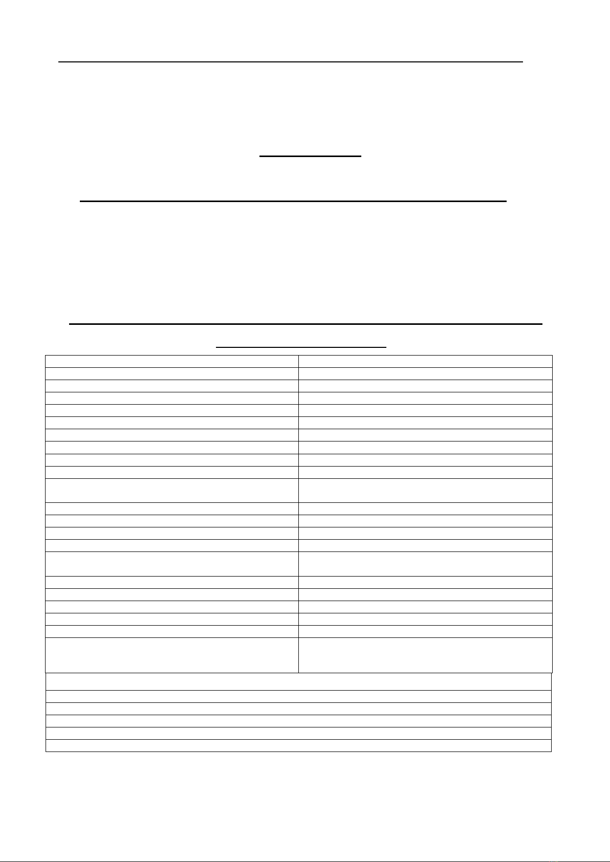
SPECIFICATIONS
Circuit type
L or Π
Input capacitance step
25pF
Output capacitance step
12pF
Inductance step
0.04μΗ
Total input capacitance
3200 pf DIPPED SILVER MICA
Total output capacitance
1600 pf DOORKNOB CERAMIC 7.5 KV
Total inductance
40μΗ (3 mm WIRE)
Used input relays (RX114012C)
19 x SCHRACK (1KV withstanding voltage)
Used output relays (GR6JNB218)
10 x like GIGAVAC (8KV withstanding voltage)
Operating frequencies
1.8 to 30 ΜΗΖ
Maximum power for 25 meters antenna
4 KWpep => SSB & CW (1 KW => AM, FM, RTTY &
ALL CARRIER MODES FOR A SHORT TIME! )
ATMEL controller
ΑΤ89C4051 -24P
Communication with RELAYS and memories
I2C
Maximum tuning power
50 W CARRIER
Typical tuning time
1 –4 sec.
Maximum tuning time
Memory tune time
6 sec.
0.02 sec
D.C. supply voltage
12 –16 V
Maximum supply current
1 A
Typical VSWR ( in the tuner input )
< 1.1 : 1
Maximum VSWR (in the tuner input)
< 2.0 : 1
Protection
Static discharge (NOT FOR THUNDER FALL!)
Dimensions ( without metal holder )
Weight
39.5 x 31 x 13.5 cm
7 Kg
STANDARD CONTROL BOX WIRES
LONG RED & BLACK => 12 VDC TO TRANSCEIVER POWER SUPPLY
SHORT BROWN => +12 V TO COUPLER (PIN 1)
SHORT GREY => START TO COUPLER (PIN 2)
SHORT YELLOW => KEY TO COUPLER (PIN 3)
SHORT BLACK => MEMORY CONTROL TO COUPLER (PIN 4)
4
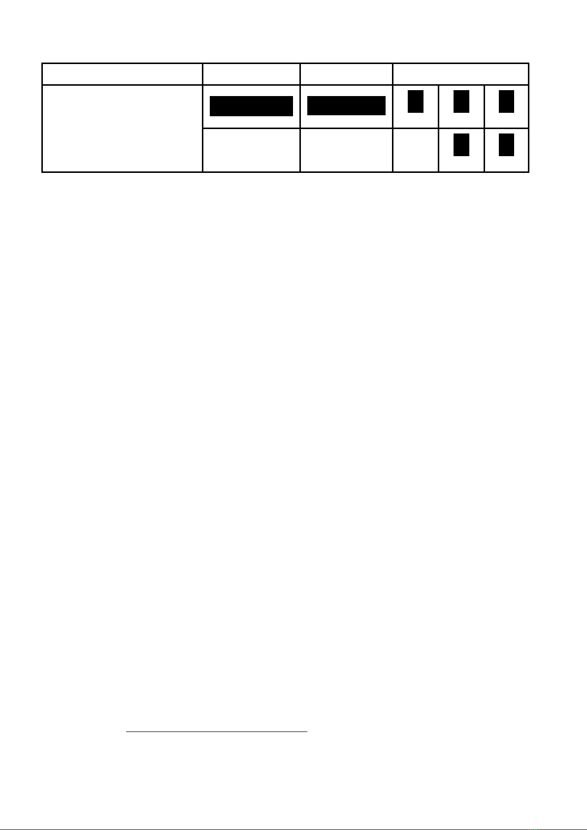
*DIRECT COMMUNICATION WITH TRANSCEIVERS
YAESU
ALINCO
ICOM
KENWOOD
YAESU does not use the KEY-
START logic. They exchange data
with their transceivers using a
single wire. So the coupler can only
cooperate with YAESU
transceivers with the standard
control box.
ΟΟΟΟΟ
Ο Ο Ο Ο
Ο
Ο
KEY
Ο
GND
GND
+12V
KEY
SRT
KEY
SRT
+12V
GND
Ο
SRT
Ο
+12V
*We connect +12V, START and KEY of the JC-5 with the appropriate connector. Τhe GND of the
transceiver’s connector does not need to be connected to the COUPLER. It gets there from the shield
of the coaxial line! The MENU of the transceiver must be programmed, if needed!
We recommend to connect the black cable to the +12v to switch the internal memories on.
If you connect the tuner direct to a radio like above you do not need the control box which is
provided. The control box is only needed if you do NOT connect a radio like above.
You can use ANY HF radio with the control box.
We recommend that you first get familiar with the external control box how the system works.
NOW, GENERALLY SPEAKING, IT IS A GOOD PRACTICE, IF A LINEAR AMPLIFIER IS USED, NOT TO
CONTROL THE COUPLER DIRECTLY FROM AN ICOM, KENWOOD OR ANY OTHER TRANSCEIVER
USING THE “KEY – START LOGIC”. BETTER USE THE MANUAL CONTROL BOX, SO THAT NOTHING
STRANGE WILL HAPPEN DUE TO STRONG RF FIELDS, IN CASE TRANSMITTING ANTENNA IS VERY
NEAR THE SHACK !
If you place the tuner outside please pay good attention to the connectors.
All connectors have to be protected with rubber tape to avoid water inside the connectors.
(Coax connector and 4 pin control connector)
TRANSCEIVER - COUPLER CONTROL CABLE: 4 x 0,75 mm or better. (Brown, Grey,
Yellow and Black are the preferred colors but it makes no difference ofcours)
If you use a short control wire (< 25 meter) a normal UTP cable will do the job.
(But use all 8 wires)
But it is common sense that UTP cable is not produced for 12 Volt DC voltage power use.
UTP is used only for low current signals like a network.
IT IS ALSO VERY IMPORTANT TO ROOT THE CABLES FEEDING AND CONTROLLING THE COUPLER AS
FAR AWAY AS POSSIBLE FROM THE ANTENNA FIELD, TO AVOID INTERFERENCE, ESPECIALLY IN THE
KEY-START COMMANDS OF THE COUPLER. IT WOULDN’T BE BAD TO USE SHIELDED 4 WIRE CABLE
FOR THE CONTROL AND EXPERIMENT FOR THE BEST POINT TO CONNECT THE SHIELD OF THE
CABLE FOR BEST RESULTS ! (NEEDS SOME EXPERIENCE, OF COURSE)
(THERE ARE CASES THE COUPLER MAY GO THROUGH OR GET A “START TUNING” COMMAND
UNEXPECTEDLY, WHILE TRANSMITTING WITH THE AMPLIFIER ACTIVATED, BECAUSE OF RF
FEEDBACK !!!)
NEVER ATTEMPT TO CORRECT THE SWR USING AN INDOOR TUNER, ESPECIALLY IF THE
EXTERNAL COUPLER UNEXPECTEDLY AND CONTINUOUSLY REFUSES TO KEEP THE SWR
AT THE LEVEL YOU KNOW IT CAN ACCOMPLISH. TAKE IT DOWN IMMEDIATELY AND
CHECK IT, BECAUSE SOMETHING MAY BE BURNED INSIDE AND THE MORE YOU INSIST
TRANSMITTING, THE MORE DAMAGE YOU MAY CAUSE !!!
5
IN ANY CASE, DO NOT CORRECT SWR WITH THE COUPLER THROUGH, USING AN
INDOOR TUNER. AS THE ANTENNA FEED-POINT IMPEDANCE IS GETTING HIGHER THAN
50 OHMS (WITH ITS MAXIMUM VALUE NEAR λ/2) THE SAME AMOUNT OF POWER
MUST BE SUPPLIED IN THE FORM OF LOWER CURRENT, BUT HIGHER VOLTAGE.
SINCE THE INPUT CIRCUITS OF THE COUPLER WERE DESIGNED TO HANDLE POWER IN
THE VICINITY OF 50 OHMS, THEY WILL BE DESTROYED !
IF THE USED ANTENNA IS NOT NEAR 50 OHMS AT THE OPERATING FREQUENCY, EVEN
WITH MODERATE POWER LEVELS, THE COUPLER MAY SUFFER !!!
Intend of use:
- This device is designed to match 1 end-fed wire in the HF spectrum to a 50 ohm coax cable.
- Use of the JC-5s beyond the specified frequency or power range can destroy it and cause safety risks.
- This product must be considered as a sub assembly, intended to be a part of an amateur antenna
installation.
- This product is exclusively intended for outdoor use, in a fire safe and explosion safe environment.
Important safety instructions:
- Read these instructions prior to installation of the product and heed warnings Retain this document.
- Apply during installation and use all possible safety countermeasures, like described in amateur radio
courses and literature.
- Install the product out of reach of persons and animals.
- Always install the product so that it cannot fall on persons or property.
- Do not attempt to modify the enclosure . Attempts to modify the enclosure will damage it and void any
warranty.
- Inspect the product on a regular basis and immediately replace if damaged.
- Install additional external lightning protection and earthing, as a means of secondary protection, and
disconnect the antenna wires during thunderstorms.
- Never work on the antennas or antenna wires during thunderstorms.
You will find the following “High Voltage Hazard” symbol on the product, indicating that the terminals (just
like the antenna itself) carry dangerous high voltages during transmission, and that caution is required, in
order to avoid electrocution or RF burns.
You will find the following "crossed out wheeled bin" symbol on the product, indicating that it can harm the
environment and it should be disposed of by the end user, separate from other types of waste.
In case of questions, please contact your local authorities regarding recycling.

6
Stockcorner Solutions: www.stockcorner.nl
Any questions you can email to: info@stockcorner.nl
The specifications and information regarding this product are subject to changes without prior notice.
All statements, information, recommendations and warnings in this user guide are deemed to be accurate,
but are given without any warranty. Users must take the full responsibility for the application of the
product.
Manual Version 7.3
Table of contents
Other Stockcorner Tuner manuals


