Stoneridge EZ-ELD 1.0 User manual

Document:
Page
Date:
EZ-ELD –PRODUCT MANUAL
1 of 14
24 Jan 2017
PRODUCT MANUAL
EZ-ELD™

Document:
Page
Date:
EZ-ELD –PRODUCT MANUAL
2 of 14
24 Jan 2017
Summary
1Compliance Statement .......................................................................................................................3
2Kit contents.........................................................................................................................................3
3Connector options ..............................................................................................................................4
3.1 Remove the 9 pin connector ......................................................................................................5
3.2 Insert the new connector ...........................................................................................................6
3.3 Wire extender (installation on site with little space) .................................................................8
4Installation Instructions: ...................................................................................................................11
5Led and Sound patterns....................................................................................................................13
6Download the EZ-ELD™ App .............................................................................................................14
7Resetting the Dongle or Factory Reset the Dongle ...........................................................................14
8Electrical Characteristics ...................................................................................................................14
8.1 Power Supply............................................................................................................................14
8.2 Bluetooth Chipset.....................................................................................................................14
8.3 GNSS Receiver ..........................................................................................................................14

Document:
Page
Date:
EZ-ELD –PRODUCT MANUAL
3 of 14
24 Jan 2017
1Compliance Statement
This device has:
FCC ID: 2AKA8-ELD100A0
IC: 22098-ELD100A0
Model: ELD1.0
PMN: EZ-ELD
This equipment complies with Industry Canada and FCC radiation exposure limits set forth for an uncontrolled
environment.
FCC Caution:
Changes or modifications not expressly approved by the party responsible for compliance could void the user's
authority to operate the equipment.
FCC Statement:
This device complies with Part 15 of the FCC Rules. Operation is subject to the following two conditions:
1. this device may not cause harmful interference, and
2. this device must accept any interference received, including interference that may cause undesired
operation.
This equipment has been tested and found to comply with the limits for a Class B digital device, pursuant to
part 15 of the FCC Rules. These limits are designed to provide reasonable protection against harmful
interference in a residential installation. This equipment generates, uses and can radiate radio frequency energy
and, if not installed and used in accordance with the instructions, may cause harmful interference to radio
communications. However, there is no guarantee that interference will not occur in a particular installation. If
this equipment does cause harmful interference to radio or television reception, which can be determined by
turning the equipment off and on, the user is encouraged to try to correct the interference by one or more of
the following measures:
Reorient or relocate the receiving antenna.
Increase the separation between the equipment and receiver.
Connect the equipment into an outlet on a circuit different from that to which the receiver is connected.
Consult the dealer or an experienced radio/TV technician for help.
RSS-Gen & RSS-247 statement:
This device complies with Industry Canada licence-exempt RSS standard(s).
Operation is subject to the following two conditions:
1. this device may not cause interference, and
2. this device must accept any interference, including interference that may cause undesired operation of the
device.
Le présent appareil est conforme aux CNR d'Industrie Canada applicables aux appareils radio exempts de licence.
L'exploitation est autorisée aux deux conditions suivantes:
1. l'appareil ne doit pas produire de brouillage, et
2. l'utilisateur de l'appareil doit accepter tout brouillage radioélectrique subi, même si le brouillage est
susceptible d'en compromettre le fonctionnement.
RSS-102 Statement:
This equipment complies with Industry Canada radiation exposure limits set forth for an uncontrolled environment.
Cet équipement est conforme à l'exposition aux rayonnements Industry Canada limites établies pour un
environnement non contrôlé.
2Kit contents
-4 OBD Connectors
-Extension Cable
-Quick Start Guide
-Product Manual
-Driver User Manual
-2 QR Code Labels
-2 Vehicle Stickers
-Double Sided Tape

Document:
Page
Date:
EZ-ELD –PRODUCT MANUAL
4 of 14
24 Jan 2017
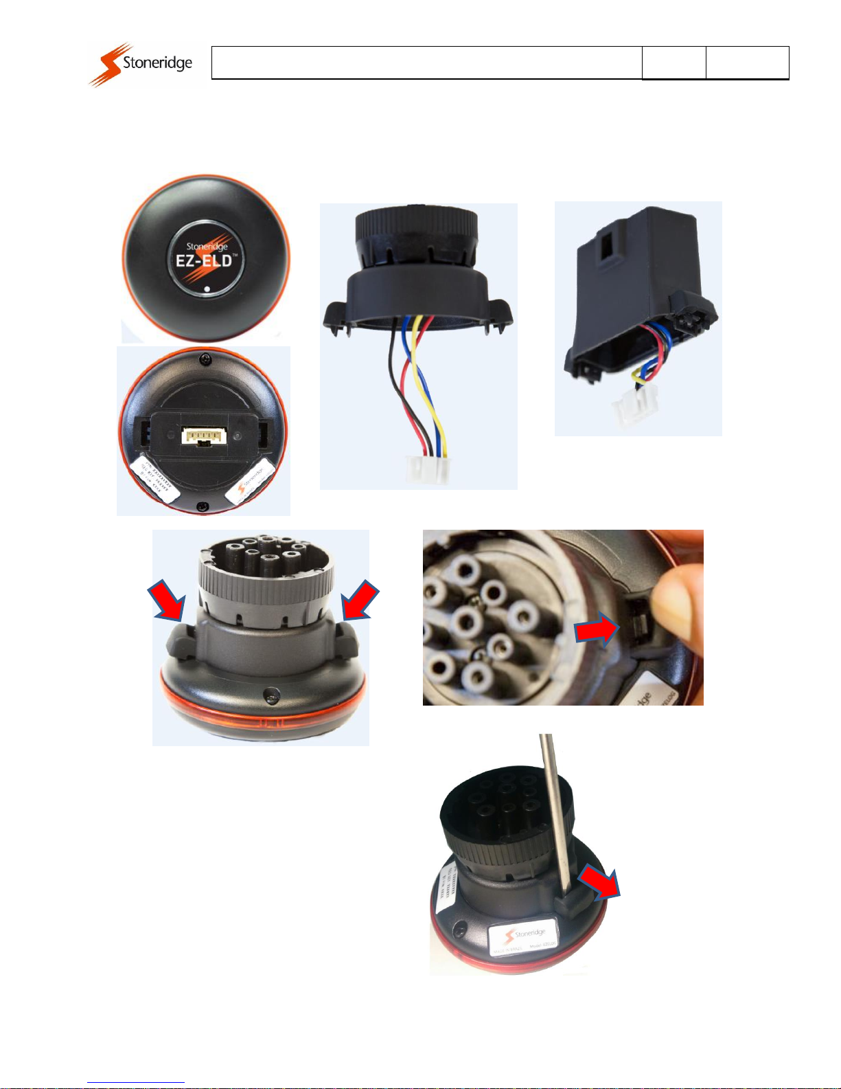
3Connector options
The EZ-ELD is shipped with the 9-pin connector already fitted. However, it also has 3 other connector
options (6-pin, OBDII Light and Medium Duty Vehicles and OBII Volvo/Mack):
ELD Dongle with 9P Connector
(Same for 6P Connector)
ELD Dongle with OBDII Volvo/Mack Connector
(Same for OBDII Light and Medium Duty Vehicles Connector)
6P Connector
9P Connector
OBII Volvo/Mack
Connector
OBDII Light and Medium
Duty Vehicles Connector
Document:
Page
Date:
EZ-ELD –PRODUCT MANUAL
5 of 14
24 Jan 2017
3.1 Remove the 9 pin connector
To change the connector type follow the guidelines of the item below.
Pull the rubber on both sides
This lock must be leveraged to outside
ELD MAIN MODULE
9P CONNECTOR
for Dongle Configuration
(Same for 6P Connector)
ELD Dongle with OBDII Volvo/Mack Connector
(Same for OBDII Light and Medium Duty
Vehicles Connector)
Document:
Page
Date:
EZ-ELD –PRODUCT MANUAL
6 of 14
24 Jan 2017
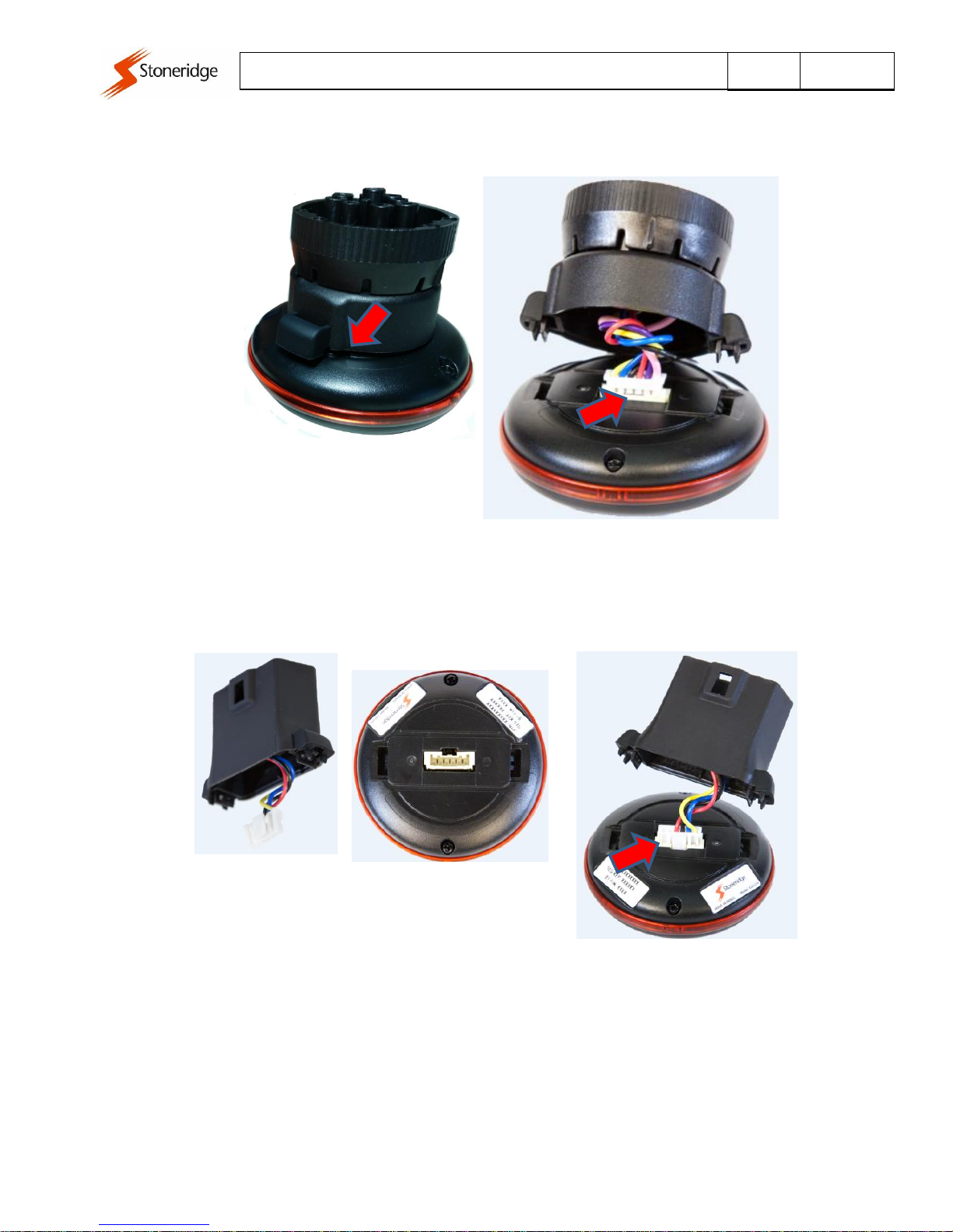
3.2 Insert the new connector
Insert a "key" in the crack and make a
lever to the inside of the module. Do one
side at a time.
Side 1 unlocked
Part 1 and 2 are unlocked.
Unplug the white connector
Plug the white connector on the module.
Attention to the correct position

Document:
Page
Date:
EZ-ELD –PRODUCT MANUAL
7 of 14
24 Jan 2017
Rotate the connector so that the wires
wrapping, thus improving the accommodation
Position the connector on the module
and press it until you hear two clicks
In accordance with the need the connector can
be mounted in one of two ways, rotated 180°.
Document:
Page
Date:
EZ-ELD –PRODUCT MANUAL
8 of 14
24 Jan 2017
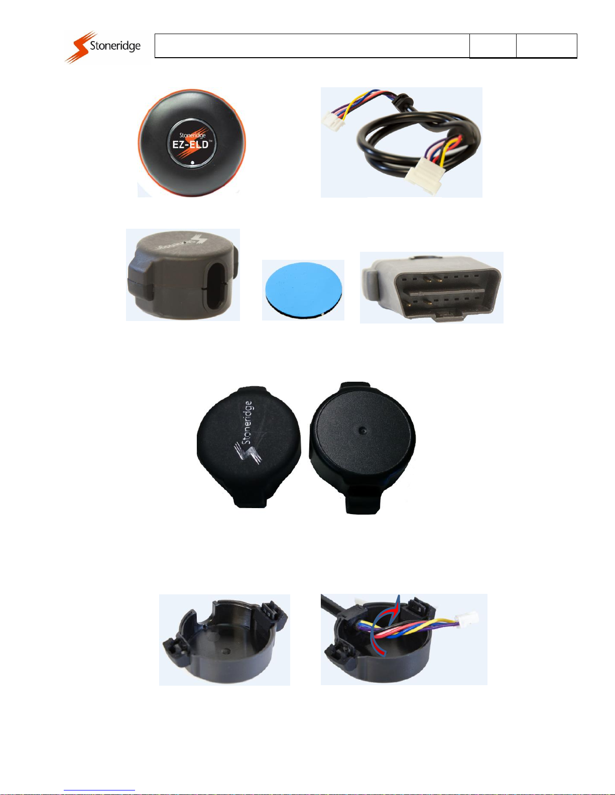
3.3 Wire extender (installation on site with little space)
ELD main module
Wire extender
Cover adapter extender whip
OBDII connector. You can
also use the 6 and 9 pins.
Double side
The Top Cover is used in the ELD main module and the Bottom Cover is used in the
connector side
Bottom Cover
Top Cover
Connect the end of the harness with female connector on the lower cover.
Wrap the wires for easy assembly in module ELD
Remove the cover by following the same steps to unplug the connector of the module

Document:
Page
Date:
EZ-ELD –PRODUCT MANUAL
9 of 14
24 Jan 2017
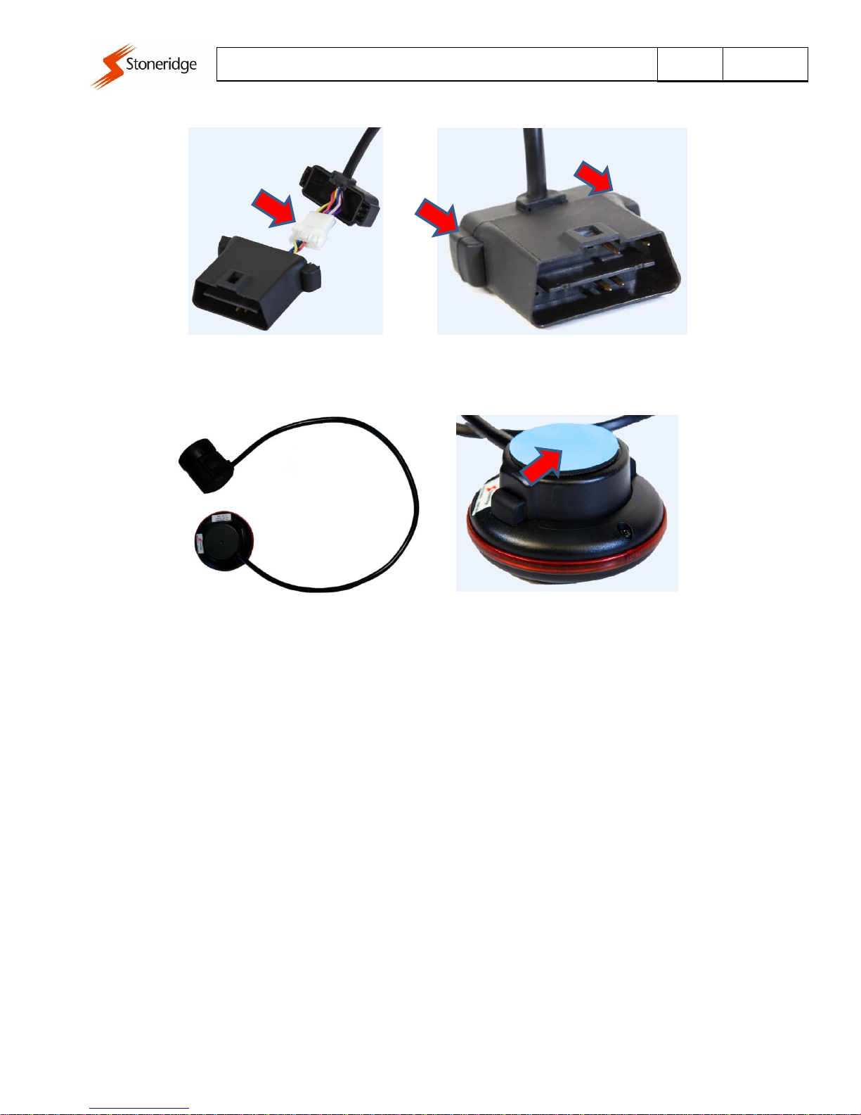
Connect the end of the harness with plug connector on the top cover.
Wrap the wires to facilitate assembly connector
ELD module
Plug the white connector on the
module to the correct position
Position the connector on the module and
press it until you hear two clicks
Bottom Cover
In accordance with the need the connector can
be mounted in one of two ways, rotated 180°.
OBDII connector. You can
also use the 6 and 9 pins.
Cover
Document:
Page
Date:
EZ-ELD –PRODUCT MANUAL
10 of 14
24 Jan 2017
Bond the double-sided tape on the
module for mounting the same
ELD module with extensor harness
Position the connector on the top cover
and press it until you hear two clicks
Plug the connector of the wire at connector
OBDII. Attention to the correct position

Document:
Page
Date:
EZ-ELD –PRODUCT MANUAL
11 of 14
24 Jan 2017
4Installation Instructions:
1. Locate the truck’s diagnostic port of the vehicle. Depending on the make and model, it may
or may not be easy to locate. There are several locations to find the diagnostic port:
oUnder the dash or under the steering column/wheel on the left or right,
oOn the left or right of the pedals, above the pedals.
oAbove the footrest
oIn the fuses box
oNear the hand break, near the clutch pedal handbrake.
oIn some cases you will also need to remove a plastic cover to find the connector.
Heavy Duty Vehicles
Deutsch 6-pin connector Deutsch 9-pin connector
Light and Medium duty vehicles
OBDII Volvo/Mack Connector
OBDII Light and Medium Duty Vehicles Connector
Document:
Page
Date:
EZ-ELD –PRODUCT MANUAL
12 of 14
24 Jan 2017
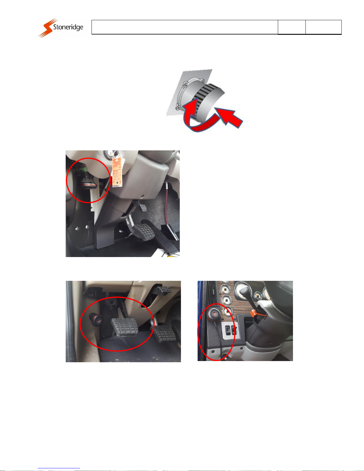
2. Attach the dongle to the vehicle’s diagnostic port. Rotate the collar to align the collar tabs
with the matching slot on the diagnostic port, press firmly until the adapter cable is fully
connected, then rotate the collar clockwise until it clicks:
Correct Installation:
Incorrect Installation:
Make sure to install the dongle in a place that will not block or interfere the pedals or with the driver.
In this case use the wire extender provided in the kit.
Document:
Page
Date:
EZ-ELD –PRODUCT MANUAL
13 of 14
24 Jan 2017
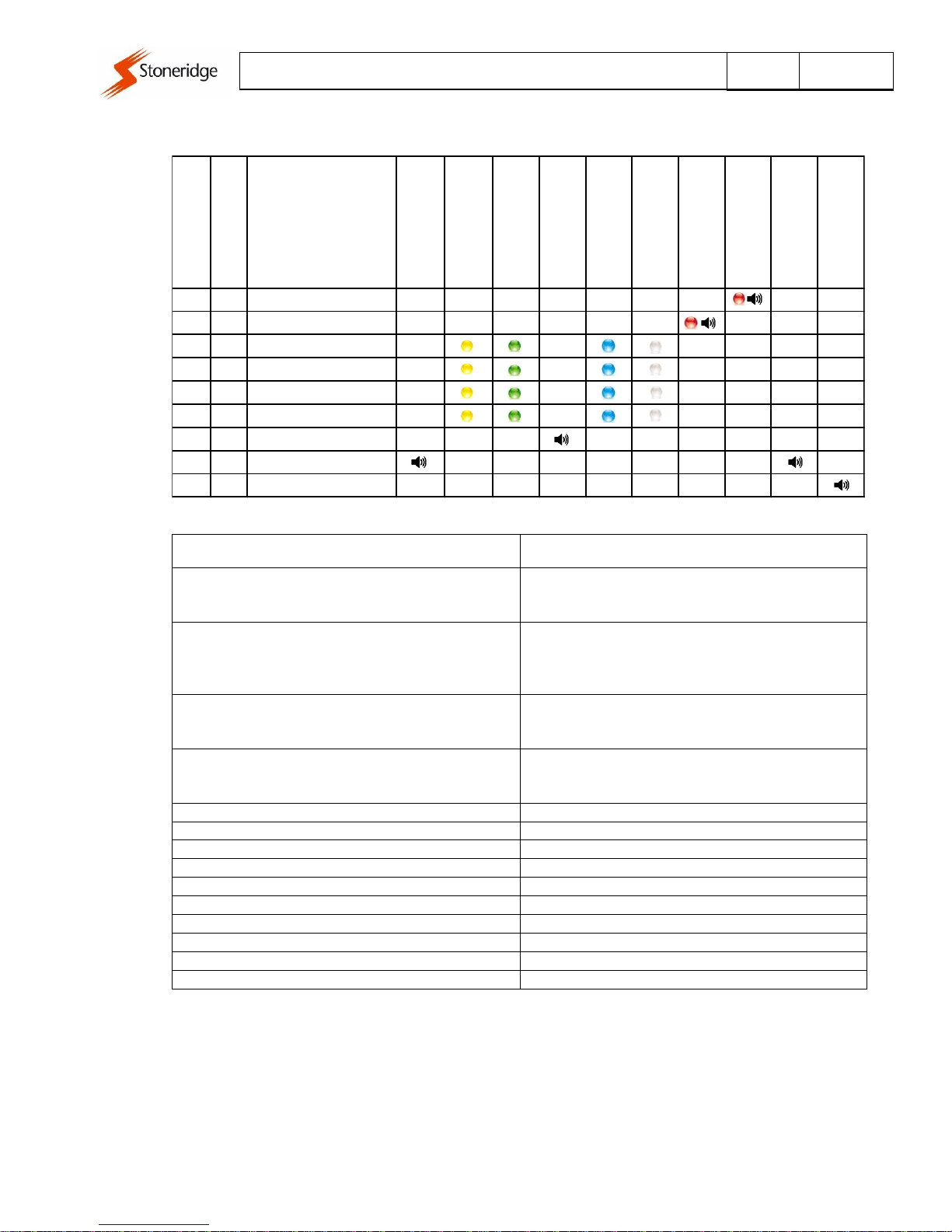
5Led and Sound patterns
Light and Sound Pattern
Indication
2 Chirps (module powered on)
Whenever you attach the dongle to the vehicle’s
diagnostic port for the first time, the buzzer will chirp
two times indicating that the module is powered ON
1 Chirp (Bluetooth paired and connected)
Press the button and release, the led will blink green
for about 40 seconds, the buzzer will chirp one time
indicating that the pairing and connection were
successfully done and Bluetooth is connected.
2 Chirps (Deleted paired devices)
Press and hold the button for about 5 seconds and
release, the buzzer will chirp two times indicating that
the paired devices were deleted on the dongle.
3 Chirps (Factory Reset)
Press and hold the button for about 12 seconds and
release, the buzzer will chirp three times indicating that
the dongle is back to a factory state.
Yellow Led
Dongle is not paired and not connected
Green Led
Dongle is in pairing mode.
Blue Led
Bluetooth is connected to an IOS device.
White Led
Bluetooth is connected to an Android device.
Red Led (Blink four times)
Malfunction detected
Red Led (Continuous blink and sound)
Vehicle in motion and driver does not log onto the ELD.
Led blink three times (yellow, green, white or blue)
GPS Not OK and Data Bus (CAN) not OK
Led blink two times (yellow, green, white or blue)
GPS OK and Data Bus (CAN) not OK
Led blink one time (yellow, green, white or blue)
GPS not OK and Data Bus (CAN) OK
Led solid (yellow, green, white or blue)
GPS OK and Data Bus (CAN) OK
GPS
Data Bus
Led/Buzzer Pattern
First Connection
Module Powered on
Not paired and
not connected
Press the pair button (Green
Light - 40 sec)
Bluetooth Connected
IOS Connected
Android Connected
Malfunction
Vehicle in motion
Driver does not log onto the
ELD
Press and hold button
approx. 4 sec
Delete Paired BT devices
Press and hold button
approx. 12 sec.
Factory Reset
- - Continuous blink and sound
- - Led blink 4 times/Buzzer
NOK NOK Led blink 3 times
OK NOK Led blink 2 times
NOK OK Led blink 1 times
OK OK Solid
- - 1 Chirp
- - 2 Chirps
- - 3 Chirps
Document:
Page
Date:
EZ-ELD –PRODUCT MANUAL
14 of 14
24 Jan 2017
6Download the EZ-ELD™ App
Download the EZ-ELD App for Android and IOS devices.
Search for EZ-ELD in the Google Play Store for Android phones and search for EZ-ELD in the App Store
for iPhones and iPads.
For information on how to use the EZ-ELD™ App, please consult the “DRIVER USER MANUAL”.
7Resetting the Dongle or Factory Reset the Dongle
If you are having problems with the Dongle, you can reset it and start again.
Resetting the Dongle will clear all the pairing data, delete any stored driving information and back the
device to a factory state.
To factory reset the Dongle:
1. Make sure the Dongle is powered on.
2. Press and hold the dongle button for about 12 seconds.
3. Release the button
4. The internal buzzer will chirp 3 times indicating that the Dongle is back to a factory state.
8Electrical Characteristics
8.1 Power Supply
Item
Min.
Typ.
Max.
Unit
Operating voltage
9
12
32
V
Average Current Consumption @ 12V (Full Power)
60
mA
Average Current Consumption @ 12V (Sleep) (*1)
1.8
mA
* 1 –After protocol recognition and vehicle with engine off and Bluetooth disconnected
8.2 Bluetooth Chipset
Type / Version
Bluetooth 4.2 Dual Mode (Classic & LE)
Frequency
2.402 to 2.480 GHz
Class / Power
Class 2 (+2 dBm typ.)
Receive Sensitivity
-90 dBm (Classic); -92 dBm (LE)
8.3 GNSS Receiver
Constellations
GPS
Number of channels
48
Horizontal Position Accuracy
(CEP, 50%, 24 hours static, -130 dBm, > 6 SVs)
2.5 m
Time-To-First-Fix
(All satellites at -130 dBm )
Cold Start: < 35 s
Hot Start: 1 s
Receive Sensitivity
Cold Start: -147 dBm
Tracking: -163 dBm
Table of contents


