Stones Sound Studio Ribbon 260 User manual
STONES SOUND STUDIO
RIBBON SPEAKER KIT
MANUAL
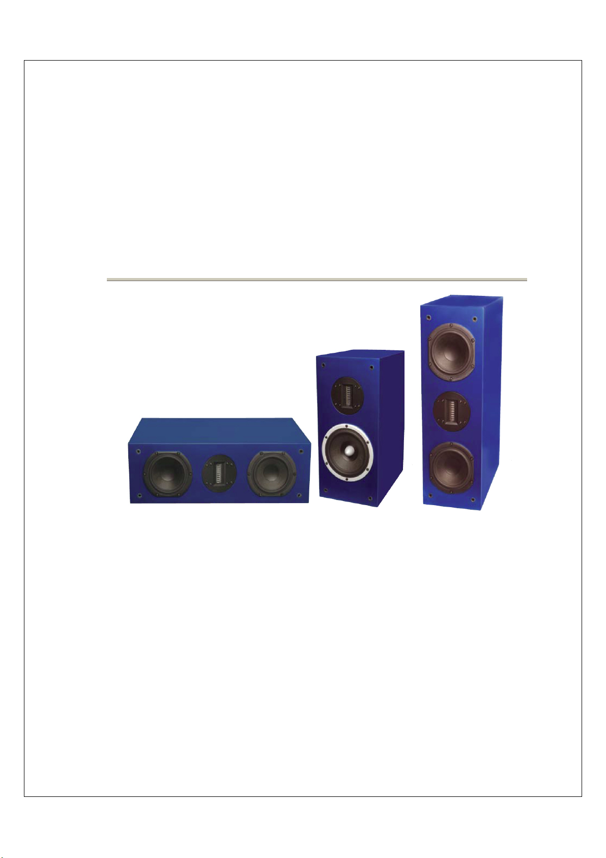
260C 360 260
Designed
By
Russell Storey
(Version V6) 19/1/08

2
Loudspeaker Description and Building Instructions

3
CONTENTS
Loudspeaker Description
The Ribbon Speaker Performance………………………………………………………………….4
Ribbon Speaker Kit Design Concept………………………………………………………………..5
Tweeter: Fountek Ribbon……………………………………………………………………………5
Woofer: Peerless Bass/Midrange……………...........................................................................5
The Ribbon Speaker Enclosures…………………………………………………..........................6
Centre Speaker………………………………………………………………………………………..6
Enclosure Bracing Rib………………………………………………………………………………...6
Enclosure Felt Damping………………………………………………………………………………6
Enclosure Rear Port & Port Flare ……………………………………………………………………7
Enclosure Bracing and Felt Acoustic Damping…………………………………………………….7
Grill Panel………………………………………………………………………………………………7
Enclosure Features Summary………………………………………………………………………..7
Crossover 260 260C 360……………………………………………………………………………..8
Crossover Features Summary……………………………………………………………………….8
Speaker Cable type internal wiring & amplifier……………………………………………………..8
Loudspeaker Connection
Speaker Cable Wiring (Standard) ……………………………………………………………………9
Speaker Cable (BI Wiring)…………………………………………………....................................10
Building Instructions
Crossover Board (Bottom) 260-260C 360…………………………………………………………..11
Woofer (Bottom) 260 260C 360……………………………………………………………………...11
Fountek Jp3.0 Ribbon Tweeter………………………………………………………………………11
Ribbon 260 360 Fronts………………………………………………………………………………..11
Woofer (top) 260 260C………………………………………………………………………………11
Ribbon 260C Centre Speaker………………………………………………………………………..11
Location of Crossover PCB and Wiring 260 360 260C…………………………………………...12
Testing the Finished Speaker Box…………………………………………………………..13
Bass Speaker phase test (dc only)………………………………………………………………….13
Crossover Network Resistance (dc only) (optional)……………………………………………….13
Digital Multi Meter (DMM) Readings………………………………………………………………...13
Testing the Speaker Box Photos 2 &3 ……………………………………………………………...14
Installation Photographs…….………………………………………………………15.to.27
Fully Assembled 260 260C……………………………………………………………………………28
Fully Assembled 360…………………………………………………………………………………..29
Recommended Loudspeaker Room Location.................................30
How to make Port and Port Flare & Enclosure Felt Damping………..31 to 38

4
Loudspeaker Description
The Ribbon Speaker Performance
Here at Stones Sound Studio we have engineered Super High Definition Ribbon Speakers
to reproduce all analogue and digital stereo programs including CD, HD-DVD,SACD analogue
turntables and multi channel A/V home theatre sound systems
The 260 260c & 360 Ribbon Speakers provide excellent depth of field, holographic 3D sound
staging, fast tight bass midrange, crystal clear top end detail, extreme dynamic range with very
low distortion on any type of program material from low to high volume levels
The 260C centre channel speaker complements the 260 and 360 ribbon speakers for high-end
Home Theatre A/V systems. I recommend complementing the ribbon speakers with the high
quality R1000 12” subwoofer for very low frequency articulate bass for medium to large rooms
The 260 and 360 ribbon speakers have been designed to become a sound reference for both
home theatre and audio systems enabling listeners to hear finer instrument detail in analogue
and digital recordings
The low distortion, wide bandwidth and large dynamic range provided by this Ribbon Speaker
series enables listeners to appreciate the effects of any upgrades or changes made to their
electronic equipment , cables ,components and program material providing many years of
enjoyable listening.
Russell Storey
5
Loudspeaker Description
Ribbon Speaker Kit Design Concept
The aim of a good high definition loudspeaker is to reproduce any instrument or sound as realistically and as close as
possible to the original sound source .While these attributes are achievable to a degree using a standard woofer /soft,
dome tweeter combination an even better solution is a woofer /ribbon tweeter loudspeaker. I chose a Pure Ribbon
tweeter because of the speed low mass and detail to enable a speaker design with true super high definition sound
reproduction of any instrument or sound effect
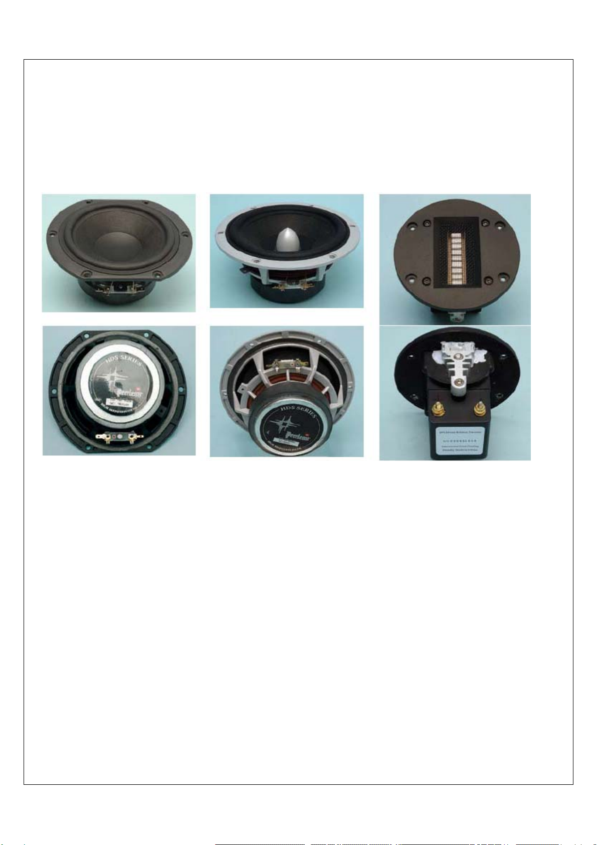
832873 5’’ 830883 6.5’’ JP3.0
Tweeter: Fountek Ribbon
The Fountek Jp3.0 pure ribbon tweeter with high frequency transformer has the ability to deliver extremely fast
transient detail and low distortion from very low to high volume levels and enables a truly realistic sound when
compared to planar ribbon or dome tweeters.
The Jp30 ribbon tweeter diaphgram has a very low moving mass of only 11mg (dome tweeter > 300mg) and is fitted
with High Flux density rare earth neo magnets. To convert very the low impedance of the ribbon diaphgram to an
8-ohm primary the Jp3.0 is fitted with an ultra wide bandwidth 120 KHz transformer, resulting in a flat frequency
response minimum phase change from 1 to 40 kHz.
Woofer: Peerless Bass/Midrange
To complement the speed ,dynamics and accuracy of the JP3.0 ribbon tweeter the Peerless HDS 832873 5''
and HDS 830883 6.5” with Nomex paper cones were selected for their natural sound signature, excellent bass
lower mid range detail very low distortion , wide dynamic range , fast transient time , phase and frequency response.

6
Loudspeaker Description
The Ribbon Speaker Enclosures
The Bass Reflex enclosure was developed using LEAP 5 wave diffraction analyzer and FFT vibration analysis
An Extended Bass Shelf ( EBS) / Butterworth low pass filter response was implemented with the enclosure to ensure
optimum low extended bass and fast transit speed from the woofers
The Enclosures feature flush mounted ribbon tweeter, rear port and are manufactured from 18mm MDF
The Front Baffle is 36mm thick laminated MFD which ensures minimum movement of driver chassis and maximum
enclosure damping for very tight bass and low cabinet resonance.
Centre Speaker
The 260C Centre Speaker has a wide horizontal sound field due to the use of an MTM speaker configuration and
provides excellent detail of voice and home theatre effects .The enclosure and crossover network are the same as
the 260 except the ribbon tweeter has been rotated 90degs on the front baffle to complement the woofer sound
fields
Enclosure Bracing Rib
Acoustically bullet shaped internal bracing ribs are fitted the side and top panels to provide strength and further
improve bass transients and reduce panel resonance modes
Enclosure Felt Damping
The enclosure is fitted with acoustic felt damping to the top bottom left & right and rear internal panels of the woofer
chamber to reduce internal mid frequency standing waves and slightly damp the mid frequency back waves from of
woofer cones. In addition, two layers of acoustic felt are fitted inside back panel
R360 R260
R260c

7
Loudspeaker Description
•Enclosure Rear Port
A rear port was employed in the ribbon speaker design to ensure a reduction of overall transducer distortion and
cross modulation generated by front ports.
With a front port a form of speaker (low frequency) distortion and cross modulation is generated by the chamber
compressed air exiting the port out of phase with the woofer creating (modulation) interference of the woofer cone
and ribbon diaphgram .This interference of the woofer cone occurs at medium to high playback levels (port
velocity) and is one of the factors reducing over all dynamic range or head room of the transducers and
speaker system.
This mechanical process is similar in principal to FM & AM radio wave modulation only in this case, the radio
carrier wave is the transducer cone or ribbon diaphgram and the modulator is the low frequency compressed air
radiated from the port.
Port Flare
A simple 63 mm (ID) port size with small flared ends was chosen over large flared ports to provide minimum port
velocity, cone excursion and minimum woofer power compression at average to high volume levels.
At average to high volume levels, large radius ports cause eddy current airflow resistance at the inlet, exit flare,
and thus more power compression, less dynamic range and increased driver distortion.
Enclosure Bracing and Felt Acoustic Damping:
An MDF timber acoustic bracing rib was designed with a bullet round over on the edges to reduced unwanted
chamber resonance, standing waves (pressure particle bunching) caused by the back waves of the bass/ mid
woofer and to reduce unwanted side panel resonant modes
Grey Felt 6mm thick acoustic material is fitted to the top,bottom,left,right and rear panels and carefully folded
over the bracing rib to act as an absorber ( air brake) on lower midrange frequencies that cause modulation of
the cone and port vent . Two layers of 6mm felt are added to the inside of the rear panel and further damping is
added the rear of the ribbon tweeter to reduce air turbulence of the rear port and interference from the back of
tweeter magnet assembly
Grill Panel
The grill panel is located on the front baffle by grill pegs and cups and incorporates the use of low loss acoustic
grill cloth. The grill frame features round over of the timber grill frame internal and external edges which reduce
diffraction of the sound generated by the speaker drivers .A special low loss grill cloth has been used to reduce
attenuation of high frequencies from the ribbon tweeter and woofer. “
To enable the very best sound quality and
listening experience I recommend the grill panel be removed from the speaker box “
Enclosure Features Summary:
•Low resonance baffle design with 36mm thick laminated 18mm MDF
•High volume level High Velocity low compression port with round over at both ends
•MDF acoustic bracing rib with bullet shaped round over on edges
•Acoustic felt damping on all walls and rear panel
•Acoustic Felt cover behind ribbon tweeter
•Acoustic grill panel cloth Low loss
•Grill panel frame internal & external frame round over’s
• woofer hot cut outs 16mm roundovers on inside edge
8
Loudspeaker Description
Crossover 260 260C 360
The Linkwitz Riley (Bessel /Butterworth) crossover unit was developed to enable good linear phase and minimum
THD distortion through the pass band and over lap regions of both the woofer and ribbon tweeter whilst providing
wide dynamic range and excellent low mid and high level continuity of detail .
A 2nd order low pass with a 3rd order high pass filter slope was chosen after evaluating many different design
combinations to provide optimum isolation between low and high frequencies. Time compensation of the driver xyz
location and rising peaks response in the woofer and tweeter on and off axis were reduced buy fine tuning crossover
component values thus enabling coherent coupling from bass to tweeter combination through out the crossover
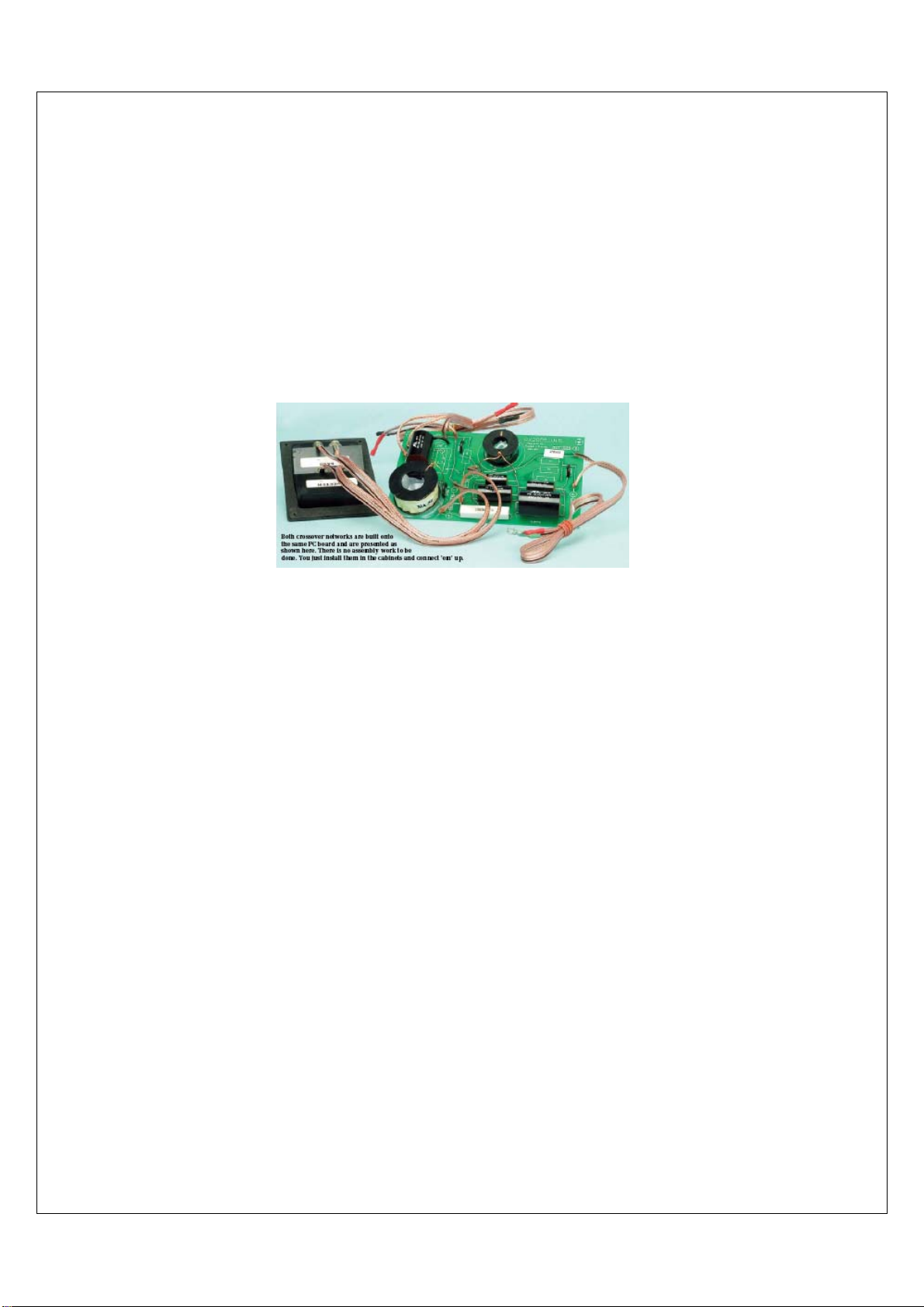
region. The fully finished crossover PCB includes all components, high quality internal wiring and Velcro mounting
tabs
Components used in the Ribbon Speaker crossover are High quality Non-Inductive resistors, Copper Air core
Inductors, SCR 400V metalized MKP capacitors.OFC 384 strand copper wiring
Crossover Features Summary
•Fully finished PCB includes all components and wiring ready to install
•Soldering: None required Wiring cable: Internal speaker cable high quality OFC 384 strand with push on
connections
•Speaker terminals: 4mm twin gold plated binding post
•Filter 2 way off set Bessel / Butterworth, linear phase
•Frequency: 260 260c 3.8 KHz 360 Freq 3.2Khz
•Order: 2nd Lp, 3rd Hp
Speaker Cable type internal wiring & amplifier
OFC 384-speaker cable is made from a low loss pure OFC copper. The cable is a type of Litz wire construction
formed from 384 thin copper wires woven into a low profile flat rectangular shape and then insulated with a clear
polymer jacket. This excellent combination of shape and size ensures the OFC 384 speaker cable has minimal
HF loss from the skin effect found in round conductors and also enables a lower overall impedance which
provides better bass depth, midrange transients and dynamics.
Other speaker cable I recommend to are QED Nordost Chord Kimber Audio Quest

9
Loudspeaker Connection
260 260C 360
Speaker Cable Wiring (Standard)
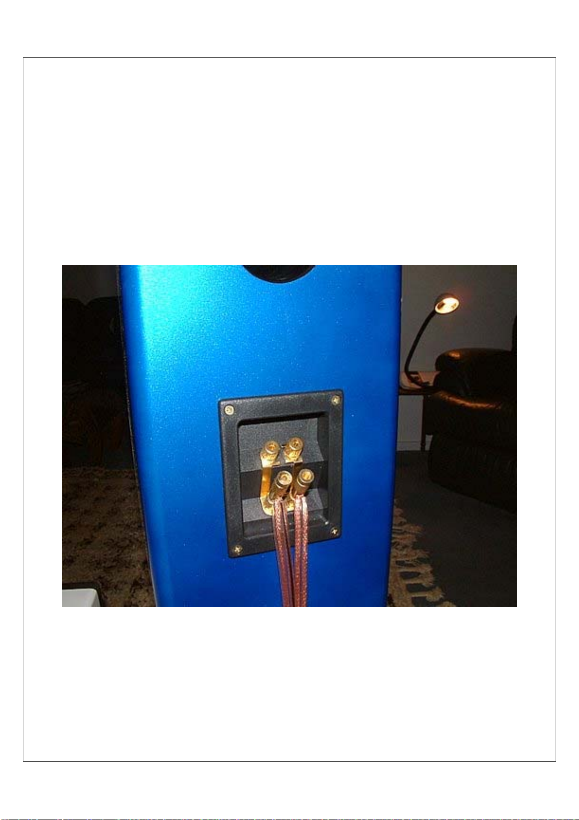
Connect the speaker cables to the bottom pair of terminals on the rear speaker terminal cup for a standard connection
to your amplifier
10
Loudspeaker Connection
260 260C 360
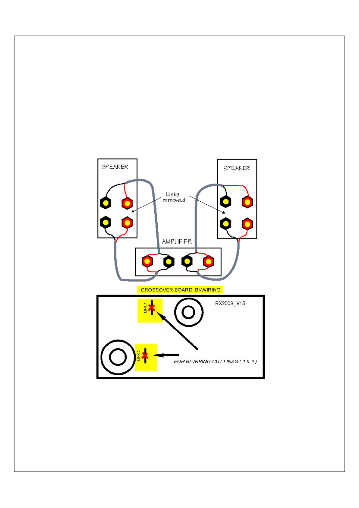
Speaker Cable (BI Wiring)
The term bi-wire simply refers to the fact that you will be running
two sets
of loudspeaker cables from your amplifier to
each
of your speakers.
9Remove the 2 links from the
rear
speaker terminal cup .
9Cut links (1,2,) on the
internal
crossover board
.

11
Building Instructions
260 260C and 360
Installation of the Woofer & Crossover PCB
1) Crossover Board (Bottom) 260-260C 360
9Fit Velcro Tabs to underside of the crossover PCB (see p17)
9Fit crossover assembly through lower woofer hole and secure with 5 Velcro tabs onto the felt at bottom of speaker
box (see p18)
9Fit speaker 4 terminal plate through felt and rear panel mounting hole then secure with 4 MDF countersunk wood
screw(see p19 p20)
2) Woofer (Bottom) 260-260C 360
9Fit Lower bass /mid speaker crossover cables through the front baffle hole (see p21)
9Fit push on connectors from the crossover speaker cables Red (+V) and Black (-ve) to the speaker terminals of the
lower woofer (see p21)
9Fit lower bass /mid speaker to the front baffle with six Allen head screws using a 3mm Allen key
9Re check all driver screws but do not over tighten (see p22 23)
3) Fountek Jp3.0 Ribbon Tweeter (Installation Check List)
9 Check acoustic felt cover is fitted behind tweeter cut out hole before installing tweeter
9 Do not connect a battery or dc ( direct voltage) across ribbon terminals .Ribbon has been pre tested in factory
9
Do not remove Ribbon protection label until speaker box the installation and dc testing
is completed
(see 27
4) Fountek Jp3.0 Ribbon Tweeter 260-260C 360
9Fit ribbon tweeter crossover cables through the bottom edge of felt cup through the front baffle hole and secure
the 2 cable lugs Red (+V) and Green (-ve) to the ribbon terminal posts with a small wrench and tighten nuts firmly
but do not over tighten See (photo p24)
Hint: Angle tweeter cable lugs to allow enough room between felt cover and back of the tweeter when installing
9Fit ribbon tweeter to the front baffle with four Allen head screws using a 3mm Allen key Re check all screws
but do not over tighten
5) Woofer (Top) 260 260C
9Fit upper bass /mid speaker crossover cables through the top front baffle hole
9Fit push on connectors from the crossover speaker cables Red (+V) and Black (-ve) to the speaker terminals of the
top woofer (see p21)
9Fit upper bass /mid speaker to the front baffle with six Allen head screws using a 3mm Allen key
9Re check all driver screws but do not over tighten
96) Ribbon 260C Centre Speaker
9Fit Crossover Board ,bottom woofer , top woofer and ribbon tweeter as per 260 Installation steps ( 1,2,3,4,5) above
(see Centre Speaker tweeter location p22 ,23)

12
Building Instructions
Location of Crossover PCB and Wiring
13
Building Instructions
260 260C and 360
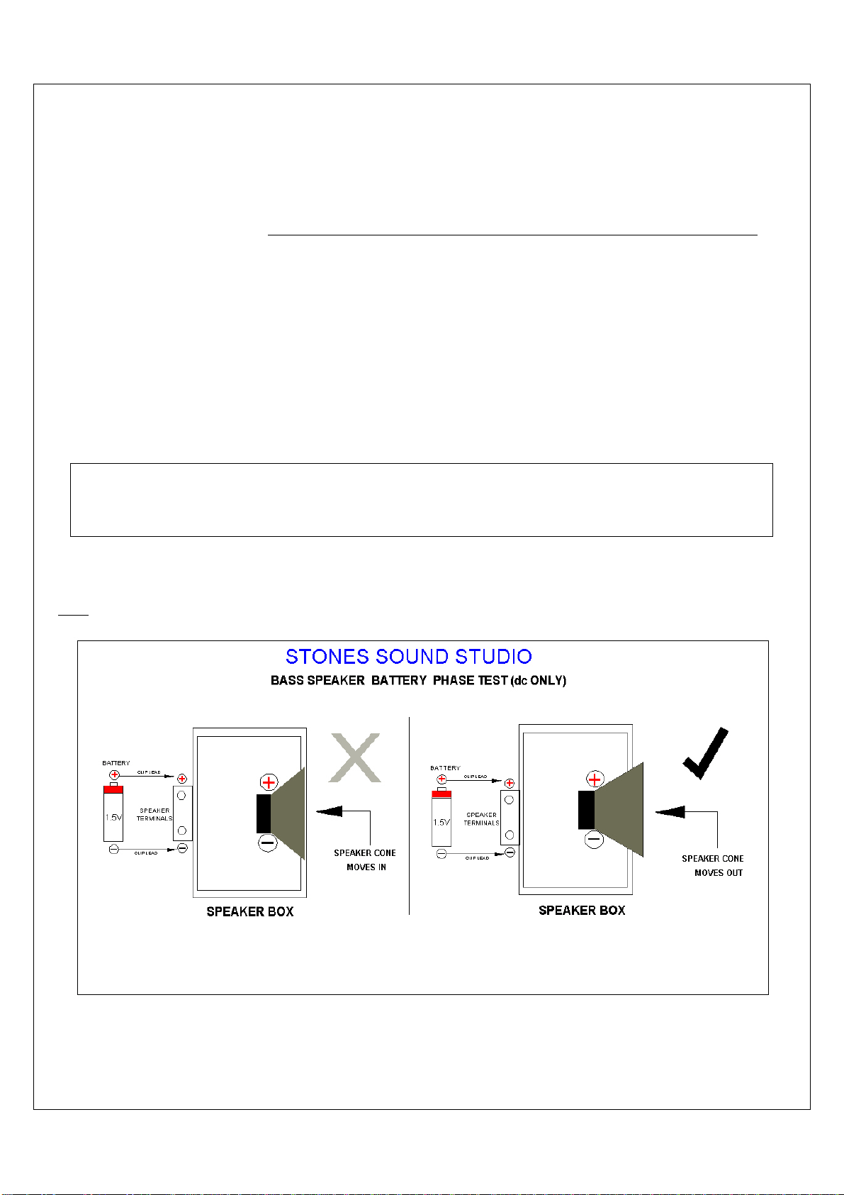
Testing the Finished Speaker Box
Bass Speaker phase test (dc only).is all that is normally required to test the pre built crossover wiring and speakers
Connect a 1.5v battery with a pair of clip leads across the bottom pair of speaker terminals (+ve to +ve ) RED and ( –
ve to –ve) BLACK. Check that the battery is connected as per photo (Photo 2 page 14).
Observe that the woofers cone moves out as per (Fig1 below).
This means the speaker and crossover wiring is connected in phase.,
If the speaker cone moves in then the connection of the bass speaker or crossover wiring are incorrect out of phase
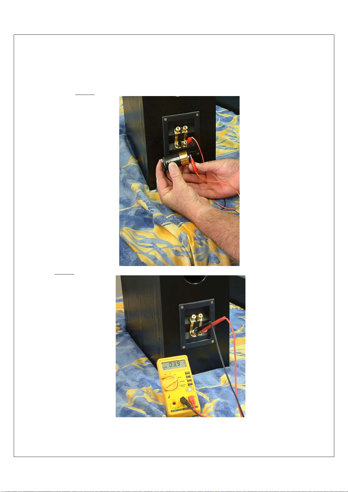
Crossover Network Resistance (dc only). (DIY optional extra for experienced Diy speaker builders and technicians)
Connect a DMM (digital multi-meter) across the bottom pair of speaker terminals then switch the DMM to the ohms
range and measure the (dc resistance) of the crossover network. see DMM photo (Photo 3 page 14)
Warning: If the DMM meter ohm readings are lower than the range given above then contact the Kit dealer for advice
Fig 1
Digital Multi Meter (DMM) Readings (average)
260 260c DMM reading range > 3.4 to 4.4 ohms (Nominal 3.9 ohm)
360 DMM reading range > 5.8 to 6.7 ohms (Nominal 6.1 ohm)
14
Building Instructions
260 260C and 360
Testing the Speaker Box Photos 2 &3
Photo 2 Bass Speaker Battery phase test (dc only)
Photo 3 DMM ohm measurement of the 260-260C speaker Crossover Network Resistance (dc only)
DMM ohm measurement 3.9 ohms 260-260C speaker
DMM ohm measurement 6 ohms 360 speaker
15
Building Instructions
260 260C and 360
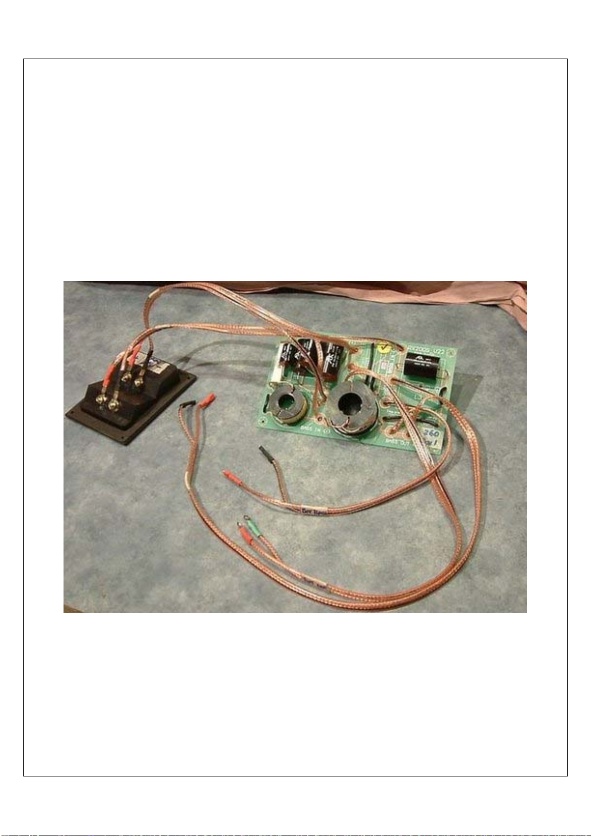
Installation Photographs
Crossover PCB assembly includes pre-wired (soldered) 4 terminal speaker cup

16
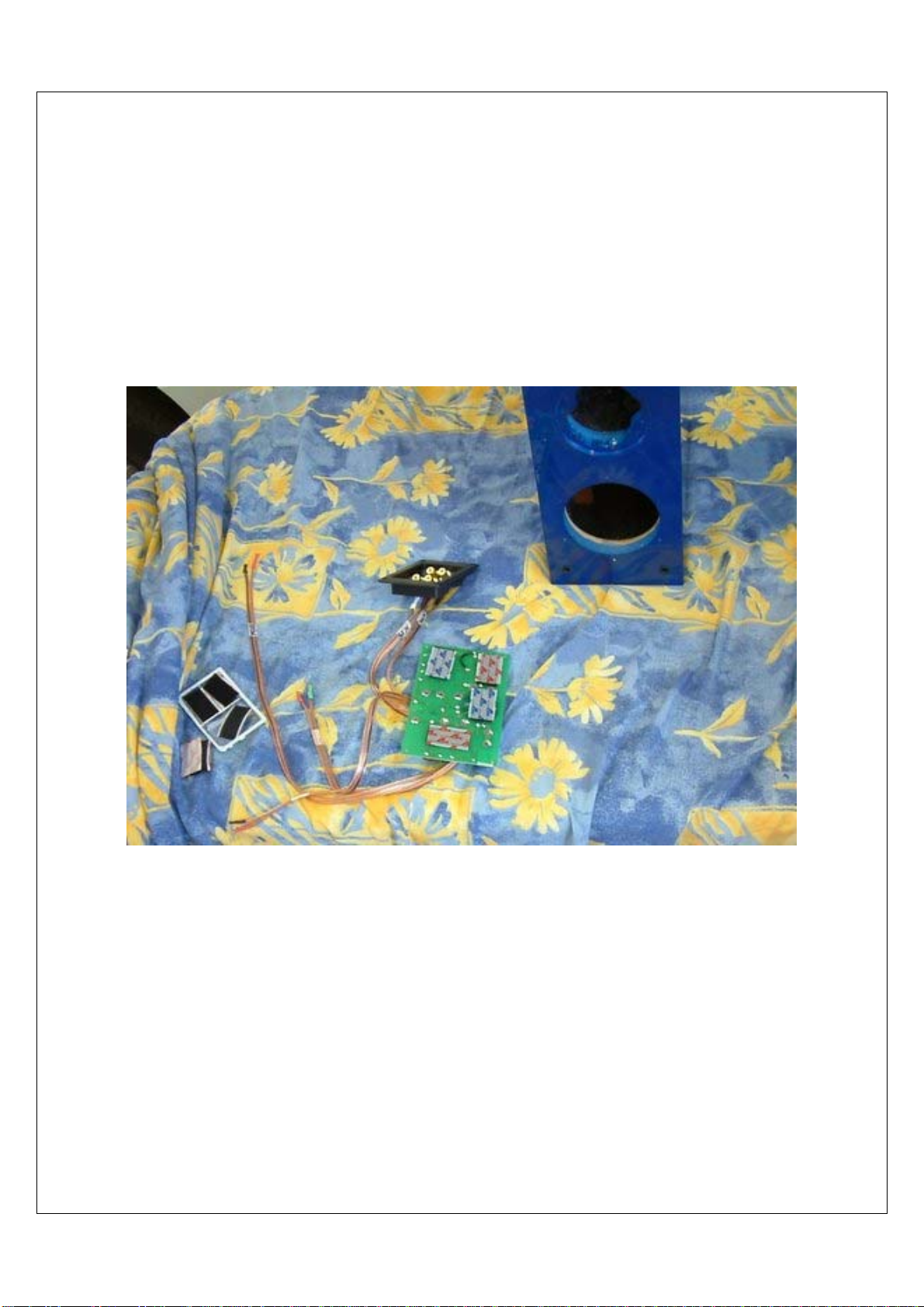
Crossover PCB assembly with 260 enclosure
17
Fit crossover assembly through lower woofer hole and secure with the Velcro tabs onto the felt at bottom of speaker box
18
Fit crossover assembly through lower woofer hole and secure with six Velcro tabs
19
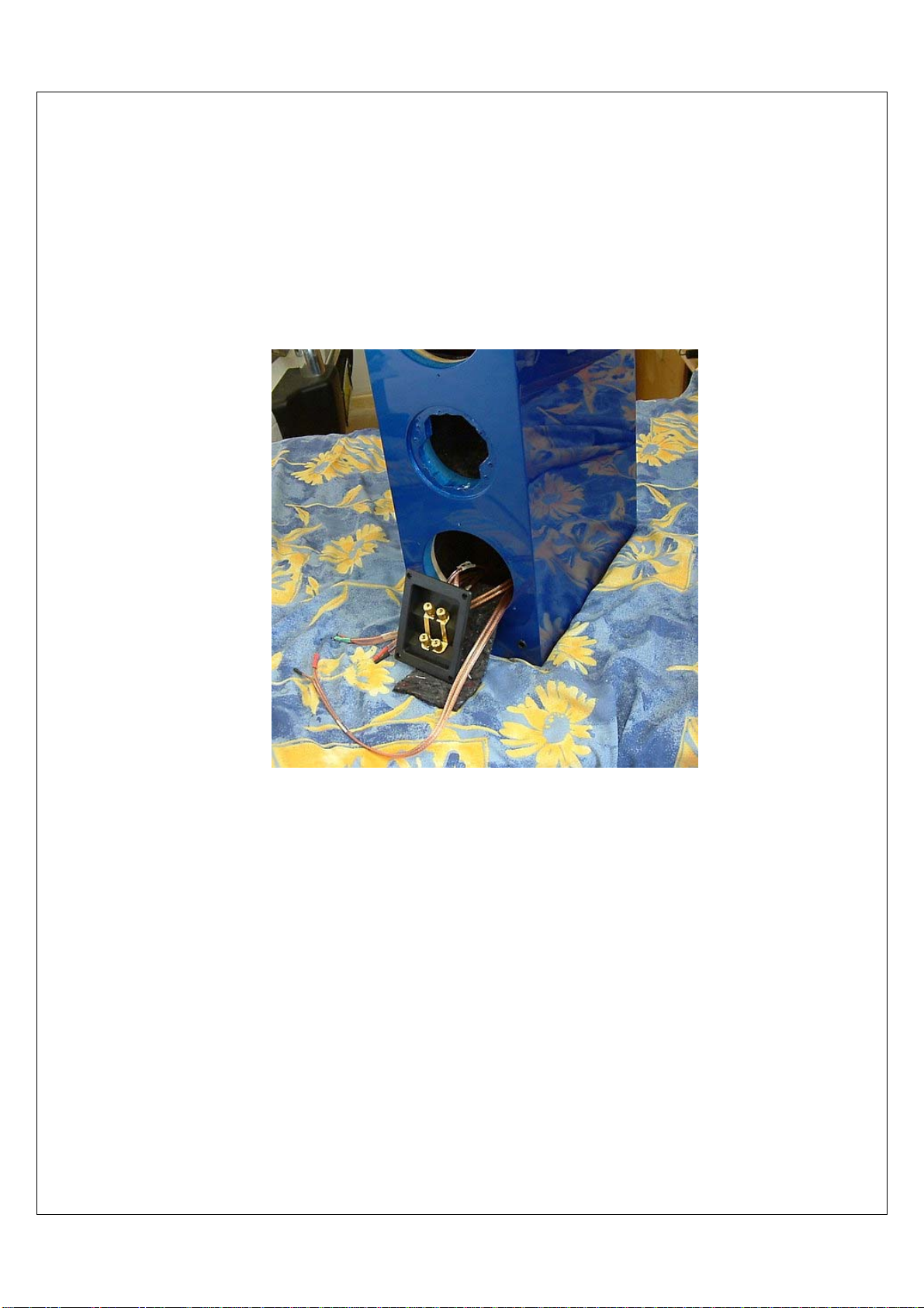
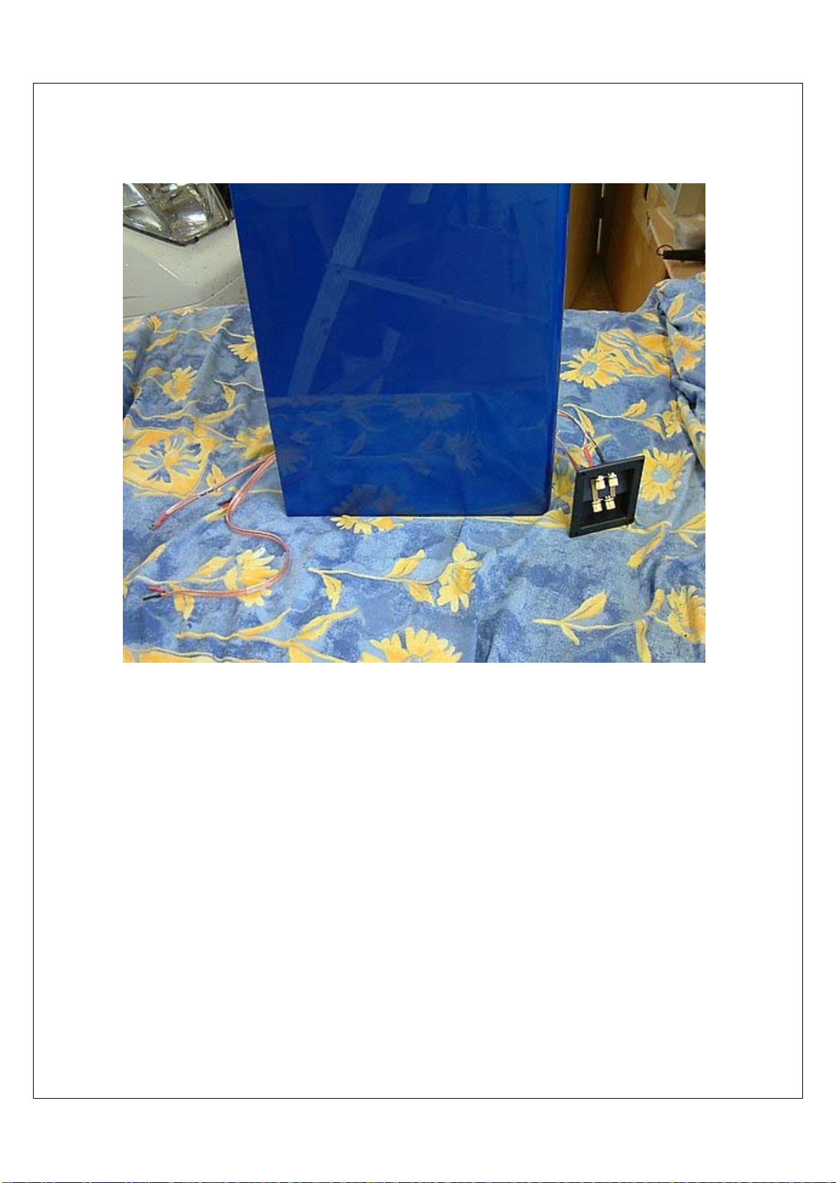
Fit speaker 4 terminal cup through felt and rear panel mounting hole then secure with 4 MDF countersunk wood screw
20
Note: Fit speaker 4 terminal cup so terminal post faces toward the top of the box
This manual suits for next models
2
Table of contents


