Stow SFCG1 SERIES Application guide

© COPYRIGHT 2004, MULTIQUIP INC.
OPERATION & PARTS MANUAL
CONCRETE SAW
SFCG1 SERIES
Revision #2 (03/10/04)
MODEL #
SERIAL #
P/N 35260
STOW CONSTRUCTION EQUIPMENT
A DIVISION OF MULTIQUIP
HANOVER MILL
FITZROY STREET
ASHTON-UNDER-LYNE
LANCASHIRE, OL7 OTL
UNITED KINGDOM
PH. 0161-339-2223
FAX. 0161-339-3226
E-MAIL: [email protected]
www.stowmfg.com
Atlanta • Boise • Newark • Quebec,Canada
Manchester,UK • RiodeJaneiro,BR • Puebla, MX
EXPORT VERSION
ORIGINAL INSTRUCTIONS


SFCG1 CONCRETE SAW — OPERATION & PARTS MANUAL — REV. #2 (03/10/04) — PAGE 3
FOR HELP AND TECHNICAL ASSISTFOR HELP AND TECHNICAL ASSIST
FOR HELP AND TECHNICAL ASSISTANCEANCE
ANCEANCE
ANCE
(UNITED KINGDOM AND EUROPE)
PLEASE HAVE THE MODEL AND SERIAL NUMBER
ON-HAND WHEN CALLING
PP
PP
PARAR
ARAR
ARTS/SERTS/SER
TS/SERTS/SER
TS/SERVICE/ WVICE/ W
VICE/ WVICE/ W
VICE/ WARRANTYARRANTY
ARRANTYARRANTY
ARRANTY
LANCASHIRE, OL7 OLLANCASHIRE, OL7 OL
LANCASHIRE, OL7 OLTT
TT
T
UNITED KINGDOM (UK) CALL:UNITED KINGDOM (UK) CALL:
UNITED KINGDOM (UK) CALL:
PHONE: 161-339-2223
FAX: 161-339-3226
STOW CONSTRUCTION EQUIPMENT
A DIVISION OF MULTIQUIP
HANOVER MILL
FITZROY STREET
ASHTON-UNDER-LYNE
LANCASHIRE, OL7 OTL
UNITED KINGDOM
PH. 0161-339-2223
FAX. 0161-339-3226
E-MAIL: [email protected]
www.stowmfg.com
Atlanta • Boise • Newark • Quebec,Canada
Manchester,UK • Rio deJaneiro,BR • Puebla, MX
Your LocalDealeris:

PAGE 4 — SFCG1 CONCRETE SAW— OPERATION & PARTS MANUAL — REV. #2 (03/10/04)
SFCG1 CONCRETE SAW—TABLE OF CONTENTS
NOTE
Specificationsand
part numbersare
subjectto change
withoutnotice.
Air Cleaner Assembly.........................................48-49
Camshaft Assembly ...........................................50-51
Carburetor Assembly .........................................52-53
Control Assembly ............................................... 54-55
Crankcase Cover Assembly...............................56-57
Crankshaft Assembly .........................................58-59
Cylinder Barrel Assembly...................................60-61
Cylinder Head Assembly....................................62-63
Fan Cover Assembly..........................................64-65
Flywheel Assembly ...........................................66-67
Fuel Tank Assembly ...........................................68-69
Ignition Assembly ............................................... 70-71
Muffler Assembly ...............................................72-73
Piston Assembly.................................................74-75
Recoil Starter Assembly.....................................76-77
Gasket Kit Assembly ............................................... 79
Labels Assembly ................................................80-81
Terms and Conditions of Sale................................. 82
Honda GX200QXC9 Engine
MULTIQUIP— SFCG1 CONCRETE
SAW
Here's How To Get Help............................................ 3
Table Of Contents ..................................................... 4
Specifications ............................................................ 5
Dimensions ............................................................... 6
Safety Message Alert Symbols..............................7-8
Rules For Safe Operation ....................................9-11
Operation And Safety Decals.................................. 12
General Information................................................ 13
Components.......................................................14-15
Basic Engine ........................................................... 16
Guards, Covers and V-Belts...............................17-18
Blades ..................................................................... 19
Blade Placement ................................................20-22
Pre-Inspection......................................................... 23
Operation ...........................................................24-27
Maintenance ......................................................28-29
Troubleshooting (Saw) ............................................ 30
Troubleshooting (Engine)...................................31-32
Explanation Of Codes In Remarks Column ............ 34
Suggested Spare Parts........................................... 35
Component Drawings
Decal Locator.....................................................36-37
Guards Assembly...............................................38-39
Guides Assembly ...............................................40-41
Undercarriage Assembly ...................................42-43
Handle & Depth Adjuster Assembly ...................44-45
Engine & Blade Drive Assembly.........................46-47

SFCG1 CONCRETE SAW — OPERATION & PARTS MANUAL — REV. #2 (03/10/04) — PAGE 5
SFCG1 CONCRETE SAW— SPECIFICATIONS
* Nominal Mass: Mass without blade, all fluid tanks empty, any optional parts removed.
** Maximum Operating Mass: Includes blade, all fluid tanks full, any necessary components installed.
*** Hand/Arm Vibration (at handle) results with SFCG1 Saw cutting cured concrete at a depth of 12.7 mm (1/2") with a
254 mm (10") blade at FULL THROTTLE.
)enignE(snoitacificepS.2elbaT
enignE
ledoM 9CXQ002XGADNOH
epyT enignEenilosaG,VHO,rednilyCelgniS,ekorts4delooc-riA
ekortSXeroB .mm45xmm86 )ni1.2X.ni7.2(
tnemecalpsiD )ni-uc0.21(c.c691
tuptuOxaM .M.P.R0063/wk8.4 ).P.H4.6(
yticapaCknaTleuF sretiL6.3.xorppA )snollaG.S.U59.0(
leuF enilosaGelibomotuAdedaelnU rehgihroenatcO68
yticapaCliOebuL )tqSU36.0(retil06.0
dohteMlortnoCdeepS epyTthgiew-ylFlagufirtneC
dohteMgnitratS tratSlioceR
)HxWxL(noisnemiD mm533X673X313 ).ni2.31X8.41x3.21(
thgieWteNyrD ).sbl3.53(gK61
snoitacificepSwaSetercnoC1GCFS.1elbaT )mm(.nieziSrobrA ).nI57.0(mm1.91
)mm(.niyticapaCedalB ).nI01(mm452
))mm(.nihtpeDgnittuC ).nI52.3(mm6.28
)gk(.sbl*ssaMlanimoN ).bL301(gK74
)gk(.sbl**ssaMgnitarepOmumixaM ).bL311(gK15
noitisoPs'rotarepOtaleveLerusserPdnuoSdethgieW-A )A(Bd3.88
leveLrewoPdnuoSdeetnarauG )A(Bd0.011
***)eldnaHtA(noitarbiVmrA/dnaH s/m41.7
2
enignE PH5.6/wK8.4adnoH 9CXQ002XG enignEenilosaG

PAGE 6 — SFCG1 CONCRETE SAW— OPERATION & PARTS MANUAL — REV. #2 (03/10/04)
SFCG1 CONCRETE SAW— DIMENSIONS
Figure 1. SFCG1 Concrete Saw Dimensions
SideView
Front View
snoisnemiDwaSetercnoC1GCFS.3elbaT
RETTELECNEREFER NOITPIRCSED )MC(NOISNEMID
A
)desiaRylluFsraBeldnaH(thgieHxaM ).nI57.64(MC7.811
B
)derewoLylluFsraBeldnaH(thgieHxaM ).nI0.23(MC3.18
C
)derewoLretnioPtnorF&desiaRylluFsraBeldnaH(htgneLxaM ).nI86(MC7.271
D
)desiaRretnioPtnorF&desiaRylluFsraBeldnaH(htgneLxaM ).nI84(MC9.121
E
)desiaRretnioPtnorF&derewoLylluFsraBeldnaH(htgneLxaM ).nI93(MC99
F
htdiWllarevOxaM ).nI5.31(MC3.43
G
noitcelfeDraBeldnaHxaM ).nI57.41(MC5.73
)HxWxL(noisnemiDdetarC ).nI32x.nI5.31x.nI5.43(MC4.85xMC3.43xMC6.78

SFCG1 CONCRETE SAW — OPERATION & PARTS MANUAL — REV. #2 (03/10/04) — PAGE 7
Safety precautions should be followed at all times when
operating this equipment. Failure to read, understand and
comply with the Safety Messages and Operating Instructions
could result in injury to yourself and others.
FOR YOUR SAFETY AND THE SAFETY OF OTHERS!
This Owner's Manual has been
developedto provide instructions
forthe safeandefficient
operationofthe SFCG1
Concrete Saws. Forengine
maintenanceinformation, please
referto theengine manufacturer's
instructionsfor datarelativeto its
safeoperation.
Before using this Concrete Saw, ensure that the operating
individual has read, understands, and complies with all
instructions in this manual.
SAFETY MESSAGE ALERT SYMBOLS
The three (3) Safety Messages shown below will inform you
about potential hazards that could injure you or others. The
Safety Messages specifically address the level of exposure to
theoperator, andarepreceded by one ofthreewords: DANGER,
WARNING, or CAUTION.
You WILL be
KILLED
or
SERIOUSLY INJURED
if you DO NOT follow these directions.
You CAN be KILLED or
SERIOUSLY INJURED
if you DO NOT follow these directions.
You CAN be
INJURED
if you DO NOT follow
these directions.
HAZARD SYMBOLS
Engine exhaust gases contain poisonous
carbon monoxide. This gas is colorless and
odorless, and can cause death if inhaled.
NEVER operate this equipment in a confined
area or enclosed structure that does not
provide ample free flow air.
Gasoline is extremely flammable, and its
vapors can cause an explosion if ignited.
DO NOT start the engine near spilled fuel or
combustible fluids. DO NOT fill the fuel tank
while the engine is running or hot. DO NOT
overfill tank, since spilled fuel could ignite if it
comes into contact with hot engine parts or
sparks from the ignition system. Store fuel in
approved containers, in well-ventilated areas
and away from sparks and flames. NEVER
use fuel as a cleaning agent.
Explosive Fuel
Burn Hazards
Enginecomponentscangenerateextreme heat.
To prevent burns, DO NOT touch these areas
while the engine is running or immediately after
operations. NEVER operate the engine with
heat shields or heat guards removed.
Rotating Parts
NEVER operate equipment with covers, or
guards removed. Keep fingers, hands, hair
and clothing away from all moving parts to
prevent injury.
NOTE
CAUTICAUTI
CAUTICAUTI
CAUTION
DANGERDANGER
DANGERDANGER
DANGER
WARNINGWARNING
WARNINGWARNING
WARNING
Potential hazards associated with SFCG1 Concrete Saw
operation will be referenced with Hazard Symbols which appear
throughout this manual, and will be referenced in conjunction
with Safety Message Alert Symbols.
SFCG1 CONCRETE SAW— SAFETY MESSAGE ALERT SYMBOLS
Lethal Exhaust Gases

PAGE 8 — SFCG1 CONCRETE SAW— OPERATION & PARTS MANUAL — REV. #2 (03/10/04)
SFCG1 CONCRETE SAW— SAFETY MESSAGE ALERT SYMBOLS
Accidental Starting
ALWAYS place the ON/OFF switch in the OFF
position, when the saw is not in use.
Over Speed Conditions
NEVER tamperwith thefactory settings ofthe
enginegovernor. Personalinjuryand damage
to the engine or equipment can result if
operating in speed ranges above maximum
allowable.
Guards and Covers In Place
NEVER operate the saw without blade guards
andcovers in place. Adheretosafety guidelines
or other applicable local regulations.
Respiratory Hazard
ALWAYS wear approved respiratory
protection.
ALWAYS wear approved eye and hearing
protection.
Sight and Hearing hazard
Equipment Damage Messages
Other important messages are provided throughout this manual
to help prevent damage to your slab saw, other property, or the
surrounding environment.
This concret/asphalt saw, other property, or
the surrounding environment could be
damaged if you do not follow instructions.
CAUTICAUTI
CAUTICAUTI
CAUTION

SFCG1 CONCRETE SAW — OPERATION & PARTS MANUAL — REV. #2 (03/10/04) — PAGE 9
SFCG1 CONCRETE SAW— RULES FOR SAFE OPERATION
The following safety guidelines should always be used when
operatingthe SFCG1Saw.
SAFETY
■
DO NOT operateorservicethisequipment
before reading this entire manual. The
manualmustbekeptavailableandaccessible
totheoperator.
■
Thisequipmentshouldnotbe operatedbypersonsunderthe
minimumstatutory agelimit.
■
ALWAYS useextremecautionwhenworkingwithflammable
liquids. When refueling, STOP the engine and allow it to
cool.
■
NEVER operate the saw in an
explosive atmosphere where fumes
are present, or near combustible
materials. An explosion or fire could
resultin severe
bodily harm or even
death.
■
NEVER touch the hot exhaust manifold,
muffler or cylinder.Allowthesepartstocool
beforeservicingthesaw.
■
The engine of this saw requires an adequate free flow of
cooling air. NEVER operate the saw in any enclosed or
narrow area where free flow
of the air is restricted. If the
air flow is restricted it will
causeseriousdamagetothe
saw'sengineandmaycause
injury to people. Remember
the saw's engine gives off
DEADLY
carbon monoxide
gas.
■
HighTemperatures –Allowtheenginetocoolbeforeadding
fuel or performing service and maintenance functions.
Contactwith
hot!
components can causeserious burns.
■
ALWAYS refuelin awell-ventilatedarea,awayfrom sparks
andopen flames.
RULES FOR SAFE OPERATION
■
ALWAYS check the saw for loosened hardware such as
nutsand boltsbeforestarting.
■
Replacenameplate, operationandsafetydecalswhen they
becomedifficult toread.
■
NEVER use accessories or attachments which are not
recommended by Multiquip for this equipment. Damage to
theequipment and/or injuryto usermayresult.
■
Manufacturerdoesnotassumeresponsibilityforanyaccident
due to equipment modifications. Unauthorized equipment
modification will void all warranties. Any modification which
could lead to a change in the original characteristics of the
machineshould bemadeonlybythemanufacturerwho shall
confirm that the machine is in conformity with appropriate
safetyregulations.
WARNINGWARNING
WARNINGWARNING
WARNING
Failuretofollowinstructionsinthismanualmayleadtoserious
injury or even death! This equipment is to be operated by
trained and qualified personnel only! This equipment is for
industrial useonly.
■
NEVER
smoke
around or near the
machine. Fire or explosion could result
from
fuel vapors
, or if fuel is spilled on a
hot!
engine.
■
Topping-offtofiller portis dangerous,asittendstospill fuel.
■
NEVER usefuelas acleaningagent.
■
NEVER operate this equipment when not feeling well due to
fatigue, illnessor takingmedicine.
■
NEVER operate the saw under the influence or drugs or
alcohol.
■
NEVER operate the saw without proper protective clothing,
shatterproof glasses, steel-toed boots and other protective
devicesrequiredfor thejob.
■
NEVER use this machine for any purpose other than those
describedinthismanual.

PAGE 10 — SFCG1 CONCRETE SAW— OPERATION & PARTS MANUAL — REV. #2 (03/10/04)
SFCG1 CONCRETE SAW— RULES FOR SAFE OPERATION
General Safety
■
ALWAYS read, understand, and follow procedures in
Operator'sManual beforeattempting tooperate equipment.
■
ALWAYS be surethe operatoris familiar withproper safety
precautionsand operatingtechniques beforeusing thesaw.
■
NEVER leave the machine
unattended
while running.
■
Apply the brakes when leaving or when using on a slope.
■
Maintain this equipment in a safe operating condition at all
times.
■
ALWAYS stopthe enginebeforeservicing, addingfuel and
oil.
■
NEVER run the engine without the air filter. Severe engine
damagecould occur.
■
ALWAYS serviceaircleanerfrequentlyto preventcarburetor
malfunction.
■
AVOID wearing jewelryorloosefittingclothing thatmaysnag
on the controls or moving parts, this can cause a serious
injury.
■
ALWAYS keepclearof
rotating
or
moving parts
while the
sawisin operation.
■
No one other than the operator is to be in the working area
when the saw is in operation.
■
Always observe all applicable compulsory regulations
relevantto environmentalprotection,especially,fuelstorage,
the handling of hazardous substances, and the wearing of
protective clothing and equipment. Instruct the user as
necessary, or, as the user, request this information and
training.
■
ALWAYS storeequipmentproperlywhenitisnotbeingused.
Equipment should be stored in a clean, dry location out of
thereach of children.
Diamond Blade Safety
■
Use appropriate steel centered diamond blades
manufacturedforuse on concrete saws. Seefurther blade
informationonpages 19 and22.
■
ALWAYS keep theworkarea wellorganized.
■
ALWAYS Clearthecuttingarea ofanydebris,tools,etc.that
wouldconstitutea hazard while thesawis in operation.
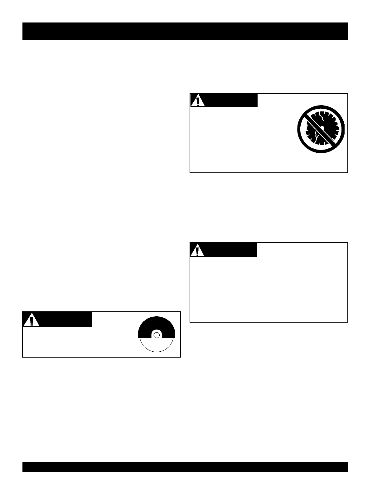
ALWAYS inspect diamond blades
before each use. The blade should
exhibit nocracks, dings,orflaws inthe
steelcentered coreand/or rim. Center
(arbor) hole must be undamaged and
true. All damaged blades must be
discarded.
ALWAYS check to make sure that the
operatingarea isclear beforestarting the
engine.
WARNINGWARNING
WARNINGWARNING
WARNING
■
Examinebladeflanges fordamage andexcessivewear.
■
Ensurethe cleanlinessofthebladebefore bladeisinstalled.
Blade should fit snugly on the shaft and against the inside/
outsidebladeflanges.
■
Ensurethe bladeis markedwithanoperatingspeedgreater
thanthespindle speedofthe saw.
WARNINGWARNING
WARNINGWARNING
WARNING
■
ALWAYS keep blade guards in place. Exposure of the
diamondblademust notexceed180 degrees.
■
Ensure that the diamond blade does not come into contact
with the ground or surface during transportation. DO NOT
dropthediamond blade onground or surface.
■
The engine governor is set to regulate maximum engine
speedin ano-load condition. Donottamperwiththe engine
governortoincreasethespeed. Increasingtheenginespeed
could allow the maximum rated spindle speed to be
exceeded,creating an unsafecondition.
■
Ensure that the blade is mounted for proper operating
direction.(See Figure 3,page 14)
■
Adhere to the Blade Manufacturer's recommendations on
handling,storage, and safeusage of blades.
Onlycutthematerialthatisspecifiedforthediamondblade.
Read the specifications of the diamond blade to ensure
thepropertoolhas beenmatchedtothematerialbeingcut.
Thesawhasbeen engineeredforDRY CUTTING. Ensure
a DRY CUTTING blade is being used.
WARNINGWARNING
WARNINGWARNING
WARNING

SFCG1 CONCRETE SAW — OPERATION & PARTS MANUAL — REV. #2 (03/10/04) — PAGE 11
SFCG1 CONCRETE SAW— RULES FOR SAFE OPERATION
Maintenance Safety
zz
zz
z
NEVER lubricate components or attempt service on a
runningmachine.
zz
zz
z
ALWAYS allow the machine a proper amount of time to
coolbefore servicing.
zz
zz
z
Keepthemachinery inproperrunning condition.
zz
zz
z
Fix damage to the machine immediately and ALWAYS
replacebroken parts.
zz
zz
z
Dispose of hazardous waste properly. Examples of
potentially hazardous waste are used motor oil, fuel and
fuelfilters.
zz
zz
z
DO NOT use food or plastic containers to dispose of
hazardouswaste.
Emergencies
zz
zz
z
ALWAYS knowthe locationof
thenearest
fire extinguisher
.
zz
zz
z
ALWAYS know the location of the
nearest
first aid kit
.
zz
zz
z
Inemergencies ALWAYS
knowthelocation ofthenearest
phone or
keep a phone on the job site
. Also know the
phone numbers of the nearest
ambulance
,
doctor
and
fire department
. Knowingthisinformation is invaluable
in the case of an emergency and could keep a serious
situationfrom becoming atragic one.
Saw Transportation Safety
■
DO NOT use the handle bars and/or front pointer as lifting
points.
■
ALWAYS use rampscapableofsupporting theweight ofthe
sawand theoperatorto loadand unload thesaw.
■
If the saw must be lifted, use the lifting bale and a crane or
forkliftwitha ratedlifting capacityforthe saw. Neverattempt
tolift thesawby yourself.
■
When transporting the saw, place the saw directly inside
towingvehicletruck-bedorontotrailerandtie-downsecurely.
■
NEVER attemptto towthe untraileredsawbehindavehicle.
■
DO NOT useonslopes oronextremely unevensurfaces.
■
NEVER tipthe enginetoextremeanglesas itmay causeoil
to gravitate into the cylinder head making the engine start
difficult.
■
NEVER load, unload, or transport the saw with the blade
mounted.
WARNINGWARNING
WARNINGWARNING
WARNING
All displacement of the machine
outside the cutting area shall be
carried out with the tool not in
rotation.

PAGE 12 — SFCG1 CONCRETE SAW— OPERATION & PARTS MANUAL — REV. #2 (03/10/04)
SFCG1 CONCRETE SAW— OPERATION AND SAFETY DECALS
Figure 2. SFCG1 Concrete Saw Decals
Machine Operation And Safety Decals
TheSFCG1ConcreteSaw isequippedwithanumberofsafetydecals(Figure2).Thesedecalsareprovidedforoperatorsafetyand
maintenanceinformation. Should anyof thesedecalsbecome unreadable,replacements can beobtained from your dealer.
P/N 36099 (ISO Blue)
P/N 35210
P/N 25427
DECAL SHEET INTL STDS
P/N 11246
LUBRICATION
CHECK HOT BELT DRIVE
P/N 15581 P/N 15580
P/N 25491
Always use approved
respiratory protection. Adhere
to safety guidelines. OSHA
Regulations (Standards-
29 CFR) 1926.136 &1910/103
WARNING
Never operate the saw without
the guards in place. Adhere to
safety guidelines: ANSI Code
29 CFR) 1910.215.
WARNING
DEPTH
CONTROL
1
2
3
4
In
(mm)
(102)
(76)
(51)
(25)
R
O
T
A
T
I
O
N
P/N 22972-003
P/N: 13118
P/N 35137
To avoid injury,
you MUST read
and understand
operator’s manual
before using this
machine.
Ask for training
as needed.
This machine to
be operated by
qualified
personnel only.
P/N 35137
WARNING
MODEL
SERIAL NO.
Engine exhaust and some of
its constituents, and some dust created
of California to cause cancer, birth
defects and other reproductive harm.
by power sanding, sawing, grinding,
drillingandotherconstruction activities
contains chemicals known to the State
Some examples of these chemicals are:
Leadfromlead-based paints.
Crystallinesilicafrombricks.
Cementandothermasonry products.
Arsenicandchromiumfromchemically
treatedlumber.
Your risk from these exposures varies,
dependingonhowoften youdothistype
of work. To reduce your exposure to
these chemicals: work in aALWAYS
well ventilated area, and work with
approved safety equipment, such as
dust masks that are specially designed
to filter out microscopic particles.
CONTACT
SERVICE
DEPARTMENT
P/N 20525
P/N 25867

SFCG1 CONCRETE SAW — OPERATION & PARTS MANUAL — REV. #2 (03/10/04) — PAGE 13
Intended Use
Operatethe SFCG1Saw, toolsand componentsin accordance
withthemanufacturer's instructions. Use ofany other toolsfor
statedoperationis consideredcontrary todesignateduse. The
risk of such use lies entirely with the user. The manufacturer
cannotbeheld liable fordamages as aresultof misuse.
Thissawisnotintendedforwetcutting.(Theuseofwatersprayed
ontothe tool [blade]during the cuttingoperation).
FAMILIARIZATION
This SFCG1-6H MiniCutter Saw is designed for dry sawing of
concrete slabs utilizing diamond blades. The saw has been
engineered for general and industrial flat sawing applications
that include: Joint Sawing of Green Concrete, Decorative
Sawing inCured Concrete,Light Demolition Sawing and "V"
Groove Beveling. The simple and compact nature of the
MiniCutter makes it a perfect sawing tool for one person to
operateandtransport. Thesaw combinesinnovative features,
top quality components, and a committed attention to state-of-
the-artmanufacturing.
For peak performance, the MiniCutter has been engineered to
operate a powerful 6.5 HP Gasoline engine and 25.4 cm (10")
diameter diamond blades. This special design allows for fast,
clean cuts in different materials at depths from 6.4 mm to 82.6
mm(1/4"to31/4").
For maximum performance and return on investment use:
Diamond Blades.
Retractable front & rear pointers with "tracking wheels" are
providedtosupportprecisestraightsawing. Thissystem permits
the operator to quickly adjust the blade cutting depth and
safeguardagainst "blade-creep"during sawingoperations. For
operator comfort and ease of transportation & storage, an
adjustable locking handle bar is provided.
Operator control of the saws is safely accomplished with
adjustablehandle bars,and aconvenientlyorientedraise/lower
leveranddepth adjustmentwheel.Anengine-offswitch(Item22
Fig. 3) located next to the handle lock allows the operator to
safelyturn theengineoff fromthe operator'spositionand away
frommovingparts.
Thejig-welded reinforcedheavy gaugesteelframeandchassis
assemblyare designedto eliminateoperational bendingand/or
flexthat wouldlead todiminished bladeperformance. Also, the
frame's general weight-to-strength ratio and center mounted
bladedesignensure accuratetracking in thecut.
A robust blade shaft bearing assembly ensures minimal flutter
and shaft harmonics providing the most advantageous
conditionsfor a diamondblade at operatingspeeds.
Heavy-duty front and rear axles, polyurethane wheels with
permanently sealed ball bearings, and solid undercarraige
assembly provide years of reliable use. The MiniCutter
incorporatesaninnovativePosiLokraise/lowercontrolassembly
that provides fingertip control of blade orientation, infinitely
adjustablelockingblade depth control,and depth feedgauge.
SFCG1 CONCRETE SAW— GENERAL INFORMATION
ENGINE
Pages23-27highlightfundamentalaspectsofengineinspection,
starting,and shutdown.Refer tothe engineOwner's Manualfor
specific instructions regarding operation, service and
maintenance.

PAGE 14 — SFCG1 CONCRETE SAW— OPERATION & PARTS MANUAL — REV. #2 (03/10/04)
CONTROLS & COMPONENTS
SFCG1 CONCRETE SAW—COMPONENTS
Figure 3. SFCG1 Concrete Saw
1
2
8
3
7
6
5
4
9
12
22
11
14
18
24
15
20
21
19
13
16
23
10
17

SFCG1 CONCRETE SAW — OPERATION & PARTS MANUAL — REV. #2 (03/10/04) — PAGE 15
Figures3showsthelocationofthebasiccontrolsorcomponents,
fortheSFCG1 ConcreteSaw.Listedbelowisabriefexplanation
ofeach controlorcomponent
1. Hand Grips/Handlebar – When operatingthe saw, place
bothhands on eachgripto maneuverthesaw.
2. Adjustable Handle – Settocomfortableoperatingposition.
3. Rear Guide – Rearguide wheeldrops intocut to assistin
straighttracking.
4. Air Filter – Preventsdirtanddebrisfromenteringtheengine
airintake. Keepcleaned andreplacewhen necessary.
5. Recoil Starter Handle – Pull to engage and start the
engine.
6. Recoil Starter Assembly – Engages the engine when
thehandle ispulled andrewindsthestarterropewhenthe
handle is released.
7. Wheels/Carraige Assembly – Heavy-dutypolyurethane
wheelswithpermanently sealed ballbearings.
SFCG1 CONCRETE SAW—COMPONENTS
8. Diamond Blade – 19.1mm (0.75" )Arbordiameter. 25.4
cm(10")bladecapacity. Thisdiameter providesforadepth
ofcut from6.4 mmto 82.6mm (1/4"to 31/4") depthof cut.
9. Blade Guard – Covers saw blade and flips up to allow
bladeto be changed.
10. BeltTension Adjuster – Adjustsbelt tension.
11. Front Guide – Assistsin straighttracking.
12. Front Guide Arm – Stows upfor storageand pivotsdown
foruse.
13. Depth Adjust Disk – Turn disk clockwise or counter-
clockwiseto adjust thecutting depth upor down.
14. Fuel Tank – Use unleaded gasoline.Do not overfill.
15. Shift Knob – Moves Depth Stop Rod in or out of keyhole
slot.
16. V-Belt Cover – Removethiscoverto gainaccess totheV-
belt. NEVER operatethe sawwith thiscover removed.
17. Arbor Shaft Grease Zerks – Conveniently located for
lubrication.
18. On/Off Switch (Engine)– Turn to the "ON" position to
allowengine tobestartedandturn tothe "OFF"positionto
preventaccidental starting.
19. Handle Lock – Lock handle height to a comfortable
operatingposition.
20. Screw Plunger – LineupbottomedgeofDepthStopRod
onScrew Plunger acrossfrom desireddepthline mark.
21. Depth Stop Rod – Holds bladeabove working surfaceor
allowsblade tocutintoworkingsurfaceatspecified depth.
22. Engine Shut-off Switch – The Engine Shutdown Switch
locatednexttothehandlelockservesbothasanEmergency
Engine Shut-Off and as the primary Shutdown switch. This
allows the operator to shutdown the saw safely away from
movingparts.
23. Dust Collection – Provides forconnectionto suitabledust
collectionbag orvacuum system.
24. Sash – Allows for the lowering and raising of the front
guidefrom theoperator'sposition.

PAGE 16 — SFCG1 CONCRETE SAW— OPERATION & PARTS MANUAL — REV. #2 (03/10/04)
Figure 4. Engine Controls and Components
INITIAL SERVICING
Theengine(Figure 4)mustbe checked forproper lubrication and
filledwithfuelpriortooperation. Refertothemanufacturersengine
manualfor instructions&detailsofoperationandservicing.
1. Fuel Filler Cap – Remove this cap to add unleaded
gasoline to the fuel tank. Make sure cap is tightened
securely.DO NOT over fill.
6. Choke Lever – Usedin thestartingof acoldengine, orin
cold weather conditions. The choke enriches the fuel
mixture.
7. Air Cleaner – Preventsdirtandotherdebrisfromentering
the fuel system. Remove wing-nut on top of air filter
cannisterto gainaccessto filterelement.
Operating the engine without an air
filter, with a damaged air filter, or a
filter in need of replacement will
allowdirttoentertheengine,causing
rapid engine wear.
8. Spark Plug – Providessparktotheignitionsystem. Clean
sparkplugonce a week.
9. Muffler – Usedto reduce noiseand emissions.
SFCG1 CONCRETE SAW— BASIC ENGINE
Adding fuel to the tank should be done only
when the engine is stopped and has had an
opportunityto cooldown. Intheeventof afuel
spill, DO NOT attempt to start the engine until
thefuelresiduehasbeencompletelywipedup,
andtheareasurrounding theengineisdry.
2. Throttle Lever – Usedto adjustengineRPMspeed(lever
advanced forward
SLOW
, lever back toward operator
FAST
).
3. Engine ON/OFF Switch – ON position permits engine
starting,OFF position stopsengine operations.
4. Recoil Starter (pull rope) – Manual-startingmethod.Pull
thestartergrip untilresistanceis felt, thenpull briskly and
smoothly.
5. Fuel Valve Lever – OPEN to let fuel flow, CLOSE to stop
theflow offuel.
NOTE
DANGERDANGER
DANGERDANGER
DANGER
WARNINGWARNING
WARNINGWARNING
WARNING
10. Fuel Tank – Holds unleaded gasoline. For additional
informationrefer toengine owner'smanual.
Enginecomponentscangenerateextremeheat.
To prevent burns, DO NOT touch these areas
whiletheengineisrunningorimmediatelyafter
operating.NEVER operate theengine withthe
mufflerremoved.

SFCG1 CONCRETE SAW — OPERATION & PARTS MANUAL — REV. #2 (03/10/04) — PAGE 17
Figure 7. Pulley Alignment
3. Check V-belt tension by using a tension meter (13.2 Kg -
19.8Kg /6.0 -9.0lbs.) againstthe insidebelt ata midpoint
betweenthetwo pulleys,orby deflectingthecenter beltata
midpoint 10mm(3/8") to13 mm(1/2"). SeeFigure 8.
SFCG1 CONCRETE SAW — GUARDS, COVERS AND V-BELTS
NEVER operate the saw without blade
guards and covers in place. DO NOT
operate with the front of the blade guard
raised. Thebladeexposurecannot exceed
180 degrees during operation. Adhere to
the safety guidelines of the American
National Standards Institute (ANSI)
B7.1 and B7.5.
Figure 5. Blade Guard
CHECK the following on the"blade guard" (Figure 5):
■
Ensurethecapacityofthebladeguardmatchesthe diameter
ofyourdiamond blade.
■
Checkthat the guardis boltedfirmlyupon thesawframe.
■
Check that the spring tensioned front cover of the guard is
firmlyseatedwith therearsection oftheguard,andthereare
nogaps. NEVER lift the bladeguard while cutting.
Figure 6.V-Belt Cover
NEVER attempt to check theV-belt with the
engine running. Severe injury can occur.
Keep fingers, hands, hair and clothing
away from all moving parts.
V-belt Alignment and Tensioning
This concrete saw is equipped with a premiumV-belt that has
been aligned and tensioned by factory personnel. The V-belt
mustbealigned andtensionedforproper operation ofthe saw.
Usethefollowingprocedure to checkthealignment ofV-belt:
1. Removethe boltsthat secure theV-beltcover (Figure6)to
thesaw frame.
2. Check uniform parallelism (Figure 7) of V-belt and pulley
(sheaves). Useastraight-edgeormachinist'ssquareagainst
both pulleys and adjust both pulleys until equally aligned.
V-belt Check
AwornordamagedV-beltcan adverselyaffecttheperformance
ofthesaw.IftheV-beltisdefectiveorworn,replaceandtheV-belt
as outlined on page 18.
CAUTIONCAUTION
CAUTIONCAUTION
CAUTION
WARNINGWARNING
WARNINGWARNING
WARNING

PAGE 18 — SFCG1 CONCRETE SAW— OPERATION & PARTS MANUAL — REV. #2 (03/10/04)
SFCG1 CONCRETE SAW — GUARDS, COVERS AND V-BELTS
Figure 8. V-Belt Tension Check
4. DO NOT over or undertightentheV-belt. Severe damage
can occur to the saw and engine crank shaft if the belt is
over-tensioned. Adecreaseofpowerto thebladeandpoor
performancewill resultifthe beltis under-tensioned(loose
onpulleys).
IftheV-beltbecomewornordamaged,replaceit withP/N15082
(Gates/Optibelt3VX335).
3. Tightentheadjustinghexscrew(4)while holdingthe engine
inplace to maintainpulley alignment.(ascrewdriver canbe
usedas a leverat therearbelt guardmountingboss tohold
thebackof the enginewhileadjustingV-belt tension.)
4. Re-tightenthe lockingnut (3).
5. With V-belt held in proper alignment, (engine parallel with
the frame), re-tighten the 4 engine mounting hex screws.
Verify thatallhexscrewsare properly tightened.
To Tighten the V-belt:
NOTE V-belt alignment must be
rechecked after adjusting belt
tension.
To Remove and Replace the V-belt:
1. Remove the 3 hex screws holding the V-belt guard and
removethe guard.
2. Loosenthe4 enginemountinghex screws.(item2,Figure9)
3. Loosen locking nut on the V-belt tension adjuster (item 3,
Figure 9). Loosen the tension on the V-belt by turning the
tensionadjusterhex screw (item4,Figure 9).
4. Pull the engine ahead to provide slack in theV-belt.
5. Loosenthe 4arbor shaft hexscrews, (item1,Figure 9).
Figure 9. V-Belt Tension Adjust
1. With V-belt guard removed, loosen the 4 engine mounting
hexscrews. (items2 Figure9)
2. Loosenlockingnut ontheV-belt tensionadjuster, (3).
6. Remove the two outer arbor shaft hex screws allowing the
outsideoftheshafttodrop,(BinFigure10),allowingremoval
oftheV-belt.
7. ReinstallnewV-belt.
8. Re-installand tightenarbor shaft hexhead screws.
9. WithV-belt heldin properalignment, re-tightenthe4 engine
mountinghexscrews.(FollowV-belttightening procedures.)
10.Re-install belt guardwith 3 hexscrews.
Figure 10.V-Belt Removal

SFCG1 CONCRETE SAW — OPERATION & PARTS MANUAL — REV. #2 (03/10/04) — PAGE 19
Failure to thoroughly inspect the
diamond blade (Figure 11) for
operational safety could result in
damage to the blade, the saw, and may
cause injury to the user or others in the
operating area. All damaged blades
must be discarded.
Figure 11. Diamond Blade
1. Drive Pin Hole – Acommonlylocatedholeonthediamond
blade core that prevents operational blade slippage
betweenthe inner&outerbladeflanges (collars). Inspect
the diameter of the hole to ensure there is no distortion,
and that a snug fit develops between the hole and drive
pin.
2. Stress Relief Holes (Gullets) – Check the steel core for
cracks that may have propagated from the slots and/or
gullets.Cracks indicate extremefatigue failure andifsawing
continues, catastrophic failure will occur.
3. Edge Of The Steel Core – Check the diameter edge for
discoloration (blue oxidation) indicating an overheating
condition caused by insufficient cooling water/air.
Overheating of blades may lead to loss of core tension
and/or increase the possibility for blade failure. Check to
make sure the steel core’s width is uniform about the rim of
the blade, and not succumbing to an “under cutting”
condition brought about by highly abrasive material or
improper under cutting core protection.
4. Directional Arrow – Check to ensure that the blade is
oriented properly on the blade shaft for sawing. Reference
thedirectionalarrow intheblade and placeitso the direction
of rotation “downcuts” with the turn of the shaft.
5. Diamond Segment or Rim – Ensure there are no cracks,
dings, or missing portions of the diamond segment/rim. DO
NOT
use a blade that is missing a segment or a portion
of
the rim
. Damaged and/or missing segments/rims may
cause damage to your saw, and injury to the user or others
in the operating area.
6. Specifications – Ensure that thebladespecifications, size,
and diameter properly match up to the sawing operation.
Utilizing a diamond blade not matched properly to the task
may result in poor performance and/or blade damage.
7. Arbor Hole – It is essential that the arbor hole diameter
properly matches the blade, and that it is free from
distortions. Correct blade flanges (collars) must be used.
Theinside face oftheflanges mustbeclean & freeofdebris.
An out of round arbor condition will cause damage to the
blade and the saw.
8. MAX RPM – This RPM reference is the maximum safe
operating speed for the blade selected. DO NOT use
blades rated at a lower rotational speed than the rated
RPM of the saw (6000 RPM). Exceeding the MAX RPM is
dangerous, and may cause poor performance and may
damage the blade. All blades must be designed to meet or
exceed the maximum spindle RPM.
SPECIFIC TOOLS TO BE USED
Thissawis to use tools(blades) as follows:
SteelCore Segmented orContinuous Diamond Rim
CuttingWheel.
Anyother typeoftool isnotto beused. SeeTable4forspecific
bladeusage for material.
WARNINGWARNING
WARNINGWARNING
WARNING
SFCG1 CONCRETE SAW — BLADES
Adhereto the BladeManufacturer's
recommendations on handling,
storage,and safe usageof blades.
NOTE

PAGE 20 — SFCG1 CONCRETE SAW— OPERATION & PARTS MANUAL — REV. #2 (03/10/04)
1. Blade Guard -Pivot theblade guardfront coveralltheway
back. The guard tension spring will keep the front cover in
position.
2. Blade Hex Nut - Unscrew the blade shaft nut (right side
loosensclockwiseand tightenscounter-clockwisewhile the
leftside loosenscounter-clockwiseandtightensclockwise.
DO NOT overtightenthenut(approximately45-50ft.lb/61-
68N/m)when finalizingthe assembly.
3. Outside Blade Flange (Collar) - Ensure that the outside
blade flange is placed flush against the diamond blade.
Theinsidesurface oftheflange mustbefree of debrisand
permita tight closureon the surfaceof thebladecore.
Cutting Depth
The SFCG1 Concrete Saw has a capacity for a 25.4 cm (10")
blade with an 19.1 mm (0.75") Arbor diameter. This allows a
cuttingrange from 0- 82.6mm(0"to3 1/4").
SFCG1 CONCRETE SAW — BLADE PLACEMENT
Failure to thoroughly inspect the diamond
blade for operational safety could result in
damage to the blades or the saw and may
cause injury to the user or others in the
operatingarea.
BLADE PLACEMENT
Diamond Blades
Selecting the diamond blade TYPE and GRADE defines how
the blade will perform both in cutting speed and blade life.
Selection of the proper diamond blade consists of:
z
Material to beCut
z
Type of Saw Being Used
z
Spindle Speed of Saw
z
Hardness Characteristicsofthe Material
z
PerformanceExpectations
Factors for sawing economy:
z
Type of Blade
z
Depthof Cut
z
SawingSpeed
z
Characteristicsof theMaterialBeing Cut
Blade Speed
Adiamondblade’sperformanceisdirectlyconnectedtospecific
peripheral(rim)speeds.
The following shaft rotational speeds have been factory set to
ensureoptimumbladeperformance.
z
SFCG1- 10”(254 mm)Capacity- 6000 RPM.
Operating saw blades at rotational
speeds greater than those specified by
themanufacturer cancause bladedam-
age, and may injure the user or others in
theoperating area.
WARNINGWARNING
WARNINGWARNING
WARNING
D
WARNINGWARNING
WARNINGWARNING
WARNING
Referto Figure 12for thefollowingcomponents.
noitceleSedalBdnAgnitsiLlairetaM.4elbaT
lairetaMedalB
etercnoCderuCedalBetercnoCderuC
etercnoCneerGedalBetercnoCneerG
tlahpsAedalBtlahpsA
etercnoCrevotlahpsAedalBetercnoC/tlahpsA
seirotcarfeR,yrnosaM,kcirB,kcolBedalByrnosaM
enotS,cimareC,eliTedalBeliT
Table of contents
Other Stow Saw manuals
Popular Saw manuals by other brands

Bosch
Bosch Professional GSA 12 V-LI Original instructions

Chicago Pneumatic
Chicago Pneumatic CP881 instruction manual

MSW Motor Technics
MSW Motor Technics MSW-BS950S user manual

Milwaukee
Milwaukee 6375-20- 6376-20 Operator's manual

Diamond Products
Diamond Products CC1700 Parts list & operating manual

Craftsman
Craftsman 113.247110 owner's manual