P 3 / 12
Repair
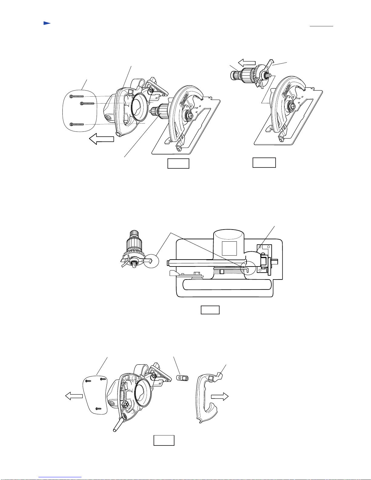
< 1 > Lubrication
Put 6g of MAKITA grease N. No.1 into gear case portion of blade case as illustrated in Fig. 1.
Also put the same one on the leaf spring of shaft lock which is sliding on blade case as illustrated
in Fig. 1 A. Put 6g of grease
here.
Helical gear 39
Fig. 1
Put the grease on the edge of
leaf spring which is sliding
on blade case.
Fig. 1 A
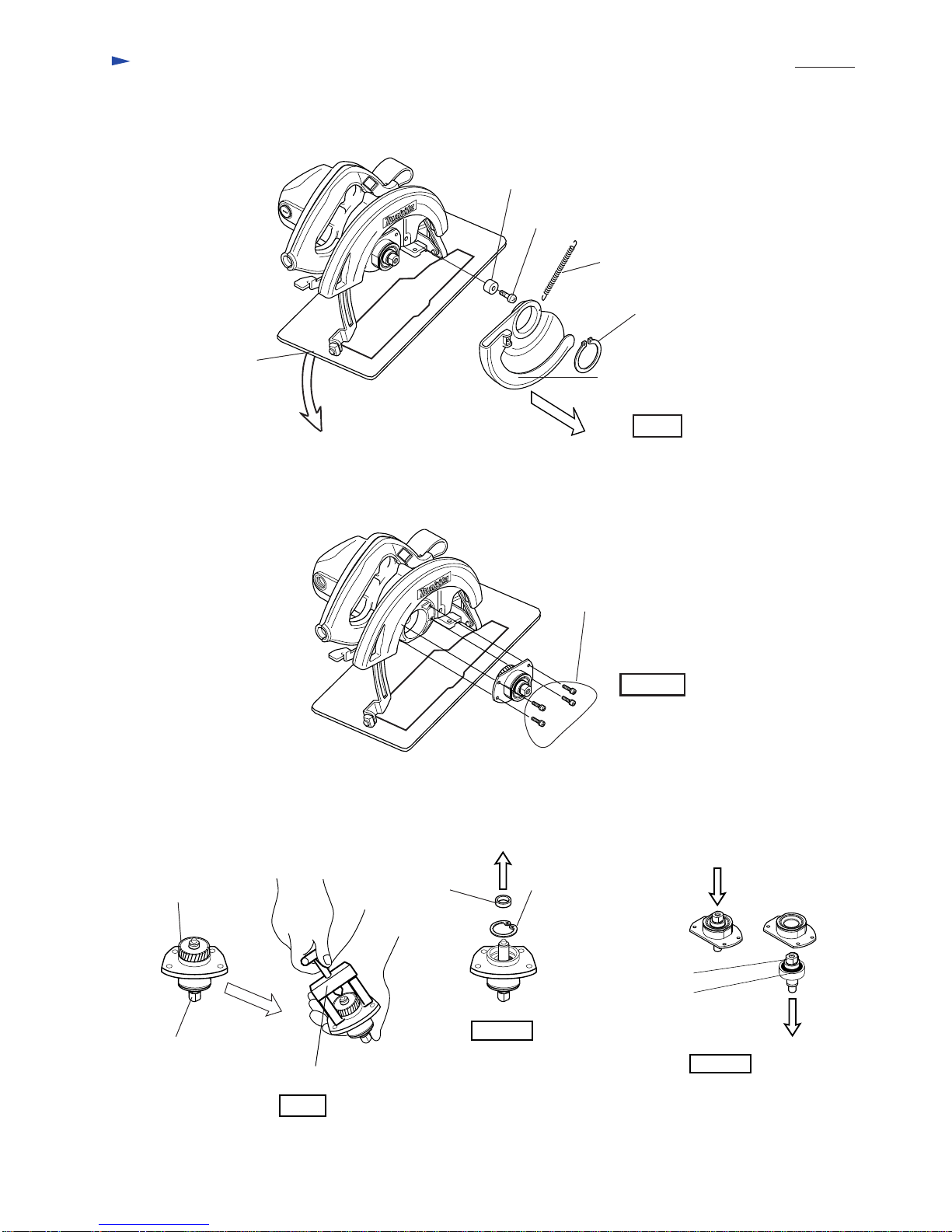
< 2 > Replacing base plate
( 1 ) For easy disassembling, adjust the cutting depth to the minimum level by pulling base plate down.
And then, separate safety cover from blade case by removing retaining ring S-42, tension spring 4, pan head screw
M6 x 20 and rubber sleeve 6 as illustrated in Fig. 2.
< Note > First of all, detach the saw blade for your safety repairing or maintenance work.
Fig. 2
( 2 ) Take off 4 pcs. of counter sunk head screws M5 x 12 which have been screwed into base plate from its bottom side
for fastening angular guide. See Fig. 3.
Depth guide
(Integrated parts of base plate)
Blade case
Cap square
neck bolt M8 x 24
4 pcs. of counter sunk head
screw M5 x 12
Fig. 3
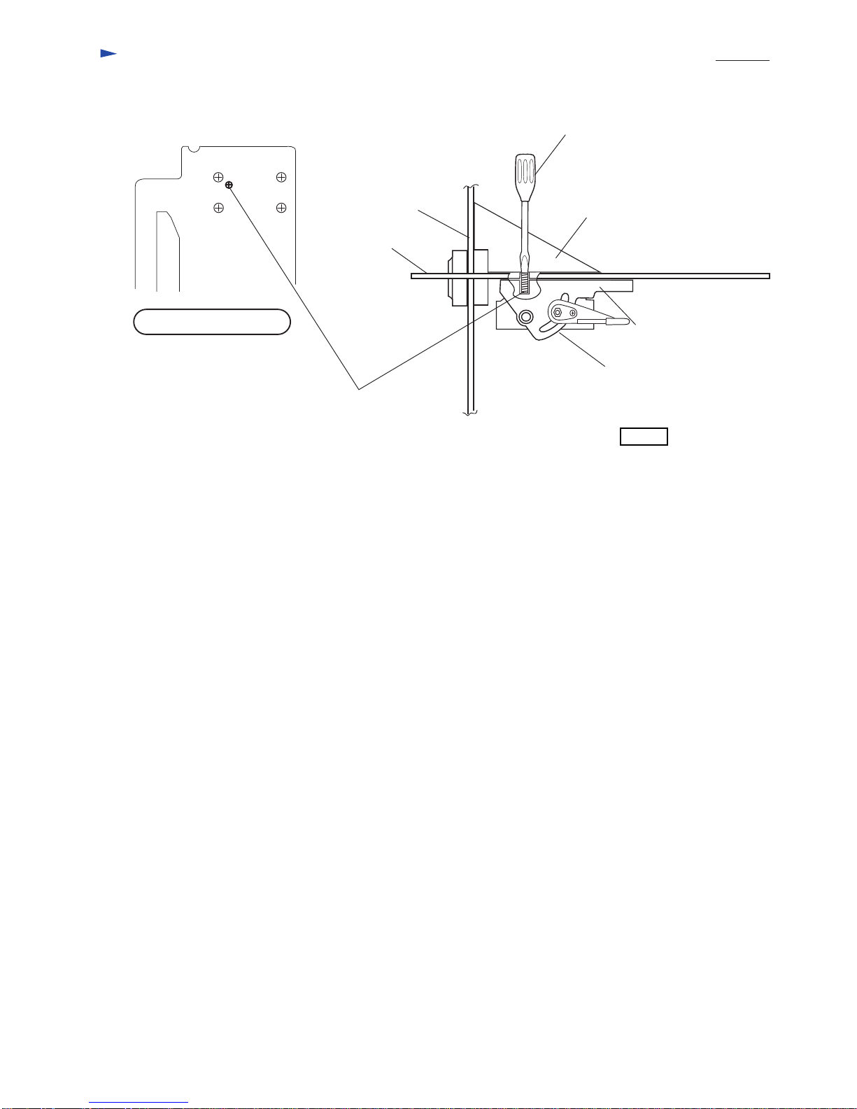
Fig. 3 A
Bottom view of base plate Fat washer 12
Fat washer 8
Lever plate
Lock plate
Pan head
screw M4 x 8 Hex nut M8
Do not touch this screw.
Retaining ring S-42
Tension spring 4
Rubber sleeve 6
Pan head screw
M6 x 20
Safety cover
Base plate
Disengage lock plate from lock lever by unscrewing pan head screw M4 x 8.
And then, unscrew hex nut M8 by turning it with disengaged lock plate. Then base plate can be separated from the
saw unit after disassembling lock plate, lock lever, flat washers 8 and 12, and cap square neck bolt M8 x 24.
See Fig. 3 A.
View from cord guard
installing side