Strathkelvin 782 User manual

Strathkelvin Instruments }782 User's Guide
Strathkelvin 782 2-Channel Oxygen System version 1.0
CONTENTS
1SAFETY AND TECHNICAL INFORMATION.......................................................1
2THE 782 SYSTEM......................................................................................................2
2.1 The 782 System...................................................................................................................................2
2.2 Minimum System Requirements.......................................................................................................2
2.3 The 782 Meter........................................................................................................................................2
2.4 1302 Microcathode Oxygen Electrodes.............................................................................................4
2.5 Computer Software................................................................................................................................5
2.6 Product Support....................................................................................................................................5
2.7 Uses of the 782 System.........................................................................................................................5
3GETTING STARTED.................................................................................................7
3.1 Software Installation.............................................................................................................................7
3.2 Setting up the 782 Meter.....................................................................................................................7
3.3 Operation.........................................................................................................................................10
4782 OXYGEN METER..............................................................................................11
4.1 Introduction..........................................................................................................................................11
4.2 Setup......................................................................................................................................................11
4.3 Calibrating your Electrodes ..............................................................................................................13
4.4 Data Logging........................................................................................................................................15
4.5 Up loading Stored Data from 782 Meter..........................................................................................17
5782 SYSTEM SOFTWARE.....................................................................................24

Strathkelvin Instruments }782 User's Guide
5.1 Introduction..........................................................................................................................................24
5.2 The Setup Screen................................................................................................................................25
5.3 Preparing the Experiment..................................................................................................................27
5.4 Basic setup............................................................................................................................................28
5.5 Setting Temperature and oxygen solubility....................................................................................29
5.6 Calibration............................................................................................................................................31
5.7 Setting Experimental Values.............................................................................................................32
5.8 Setting Recording Screen Parameters...........................................................................................36
5.9 Printing Screen Traces .....................................................................................................................37
5.10 Setting Trace Colors .....................................................................................................................38
5.11 Plotting during Setup....................................................................................................................38
5.12 Preparing to Record.......................................................................................................................38
5.13 Recording an Experiment.............................................................................................................39
5.14 Procedures in Recording..............................................................................................................39
5.15 Adding Event Markers to the Recording Area..........................................................................40
5.16 Ending Recording...........................................................................................................................40
6ANALYSIS OF DATA...............................................................................................42
6.1 Introduction..........................................................................................................................................42
6.2 Accessing the Analysis Screen........................................................................................................42
6.3 The Analysis Screen...........................................................................................................................43
6.4 Analysing Closed Cell Respirometry Files....................................................................................46
6.5 Analysing Flow-through Respirometry Files.................................................................................47
6.6 Monitoring experiments.....................................................................................................................48

Strathkelvin Instruments }782 User's Guide
7DEALING WITH REPORTS....................................................................................49
7.1 Introduction..........................................................................................................................................49
7.2 The Report page...................................................................................................................................49
8APPENDICES...........................................................................................................50
8.1 Appendix 1: Error displays ...............................................................................................................50
8.2 Appendix 2: Oxygen electrodes.........................................................................................................50
8.3 Appendix 3: Checking electrodes.....................................................................................................54
8.4 Appendix 4: Troubleshooting ............................................................................................................54
8.5 Appendix 5: Rechloriding electrode anode .....................................................................................56
8.6 Appendix 6: Calibration solutions...................................................................................................57
8.7 Appendix 7: Oxygen solubility tables...............................................................................................58
8.8 Appendix 8: Conversion units ...........................................................................................................59
8.9 Appendix 9: Electrolyte solution.......................................................................................................59
8.10 Appendix 10: References ..............................................................................................................60

Strathkelvin Instruments }782 User's Guide
1
1 Safety And Technical Information
As with all electrical equipment, care should be taken not to splash water,
especially seawater, on to the meter or electrodes.
The 782 meter conforms to the protection requirements of the
Electromagnetic Compatibility Directive as per generic standards EN50081
part 1 (emissions), and EN50082 part 1 (immunity).
If subjected to strong radiated radio-frequency interference, such as that
generated by mobile telephones at close range, a degradation of
performance, including apparent changes in electrode output, may be
expected. (Permitted Performance Class A, Electromagnetic Compatibility
Directive.)
The 782 meter conforms to the requirements of the Low Voltage Directive
73/23/EEC as per generic standard EN61010-1, part 1.
SPECIFICATION:
Inputs: 2 oxygen electrode connectors, bias voltage 650mV,
maximum input current 2.6 nA.
Connection: USB version 1.0.
Meter Power: 5V DC +/-10 %.
Plug top power unit: Input 100-240V AC, 47-63 Hz.
Output 5V DC, 2.4A.
General:
Operating Range: +5ºC to +40ºC, 20% to 80% RH.
Storage Range: -20ºC to +60ºC.
Environmental: Indoor use at altitudes up to 2000m.
Pollution Degree 1.
Safety: Complies with EN61010-1.
EMC: Complies with EN50081-1 and EN50082-1.
Size: 185 x 135 x 105 mm.
Weight: Meter: 0.66 kg; Power unit: 0.18 kg.

Strathkelvin Instruments }782 User's Guide
2
2 The 782 System
2.1 The 782 System
Welcome to the 782 2-channel dissolved oxygen measuring system.
This system offers the flexibility to either use the meter connected to a computer or to use
its datalogging facility to store your data until the meter can be attached to a computer.
This eliminates the need to spend long hours keeping notebooks of data and analysing
slopes from chart recorder traces. Everything is carried out automatically. You will be
able to conduct the whole experiment on screen, from set-up right through to tabulation of
normalised respiration rates, which can be copied to other Windows programs (eg.
spreadsheet) for graphical display or statistical analysis. The facility to print the screen
traces to a color printer is also available.
2.2 Minimum System Requirements
The 782 system is supplied as a meter, USB connecting cable, software and instruction
manual. In addition, you will need up to 2 oxygen electrodes, an electrode service kit, and
respirometer chambers available from Strathkelvin Instruments. In addition a constant
temperature water bath to maintain the electrodes within the range of ±0.05°C will be
needed. The system has been designed for the Strathkelvin 1302 Clark-type
microcathode oxygen electrodes, but should be compatible with some other low output
electrodes.
Computer and Printer
You will need a Pentium computer with a USB port and Windows 98, ME, 2000 or XP
installed. You will also need at least 6 Mbytes of free hard disk space and at least 64
Mbytes of RAM.
For many applications a color printer will not be necessary since recordings will be saved
as data files which can be recalled as required. However the facility is available for chart-
recorder-like screen traces to be printed out as hard copy. Any standard color inkjet printer
is suitable.
2.3 The 782 Meter
The meter contains the electronics needed to supply a fixed stable bias voltage to up to 2
oxygen electrodes, amplify the signal currents from them, convert them into digital values,
display and store them and/or send them to the computer.

Strathkelvin Instruments }782 User's Guide
3
Front Panel
The ON button & power indicator illuminates to indicate that the meter is receiving 5V
power. When it is pressed it switches the meter on. The electrode(s) are polarised when
they are connected and the power indicator is illuminated.
Four ‘soft’ buttons are labelled immediately above on the display. Their functions change
with the display. These only function when the meter is not connected to a computer
running the Strathkelvin software.
The display also shows the oxygen concentration values with the units (selected in setup)
plus difference (if selected in setup) and time and date (if selected in setup).
ON button &
power indicator ‘Soft’ buttons
Strathkelvin Instruments }782 User's Guide
4
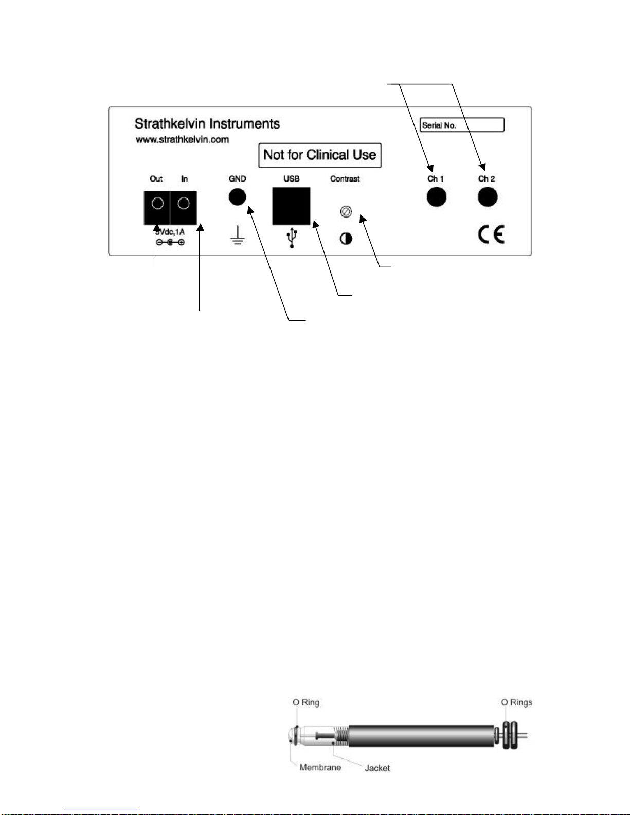
Rear Panel
The Power Out can be used to power one or two Mitocells (if purchased).
The Power In must be supplied from the 5V plug top power unit supplied.
The GND socket allows the meter to be grounded if necessary.
The meter is attached to the computer by a USB cable.
The display contrast adjuster is used to adjust the contrast and viewing angle of the front
panel display.
The Electrode input sockets (Ch1 and Ch2) receive the plugs from the 1302 oxygen
electrodes.
2.4 1302 Microcathode Oxygen Electrodes
These electrodes, which are in use worldwide with Strathkelvin's 781, 782 and 928
instruments, have the advantage of small size, high precision, and the ability to operate in
either stirred or unstirred media. They are supplied with polypropylene membranes, but for
fast speed of response, they can be fitted with FEP membranes. In this configuration, they
cannot be used unstirred and require vigorous water movement at the electrode tip. In all
applications, the electrodes have to be housed in special electrode holders or accessories
(see the Strathkelvin website: www.strathkelvin.com). These have been designed so that
only the membrane at the electrode tip comes into contact with the medium. Failure to
protect the electrode in this way can result in anode depolarisation and a shortening of the
useful life of the electrode.
The 1302 Electrode
Display contrast / viewing
angle
USB cable to computer
Socket to ground meter
Power out for
Mitocell
5V power from plug-
top power unit
Electrode inputs

Strathkelvin Instruments }782 User's Guide
5
A full description of the 1302 electrode, including theoretical considerations and details of
care and maintenance, is given in Appendix 8.2.
2.5 Computer Software
The software has been written for Windows, and has been structured so that it is user-
friendly and intuitive in use. The full power of the program is accessible to anyone with
only introductory-level knowledge of Windows. Nevertheless, it has the flexibility and
power typical of Windows programs which may be appreciated by more advanced
Windows users.
From the opening screen you will be offered the choice of either recording an experiment
or of analysing a previously recorded data set. If you choose to record, the screen
changes to the Recording Screen, in the set-up mode. The menus bring up dialog boxes
which allow you to specify the details of the experiment. These details will then be used to
set the axes and scrolling rate and other features of the recording screen. These settings
are saved and many of them will therefore not need to be set up again in subsequent
experiments. The Setup screen is also used for the calibration of the oxygen electrodes.
When recording, traces of the oxygen measurements scroll across the screen, as on a
chart recorder. The menu provides facilities for placing event markers on the screen to
indicate any changes to the preparation, such as the addition of substances to the
respirometer chambers. At the termination of recording, the data file is closed and you
have the option of analysing the data immediately or of doing this at a later date.
To calculate respiration rates or to read oxygen values from the experimental traces, the
data from the experiment are recalled from the data file to an Analysis screen. The traces
can be scrolled across the screen and expanded or contracted on the xor yaxis until the
section of trace which is of interest is optimally displayed. In respiration experiments, the
rate is automatically calculated on the selected section of trace, normalised to biomass if
required, and tabulated with all the experimental details on a Report page. Hard copy of
the results can be printed and/or the results can be exported direct to other Windows
applications.
On-screen Help is always available.
2.6 Product Support
A trouble-shooting section is included in Appendix 8.4 to assist with any problems which
might arise in the use of oxygen electrodes.
For any other problems contact Strathkelvin Instruments directly by e-mail:
2.7 Uses of the 782 System
The 782 has been designed to meet the need for replication of dissolved oxygen
measurement, with provision for up to 2 oxygen electrodes. The main uses of the system
are as follows:

Strathkelvin Instruments }782 User's Guide
6
Respiration Measurements
Respiration rate is measured in a wide variety of applications, with a variety of different
procedures and units of oxygen measurement being used. The main procedures are:
Closed cell respirometry in which a decrease in oxygen with time is measured.
This is probably the most commonly used method, so the Instruction Manual will
focus most closely on this procedure.
Flow-through respirometry in which the respiration rate is determined from the
rate of water flow, and from the difference in the oxygen concentration of water
entering and leaving the respirometer. This method has the advantage of operating
at a constant oxygen level and is particularly suitable for longer-term experiments.
Oxygen Monitoring In many situations there is simply a requirement for logging
of oxygen levels, as in the outflow of blood or saline from organ preparations. The
782 is ideally suited to log data from the oxygen electrodes in such experiments.

Strathkelvin Instruments }782 User's Guide
7
3 Getting Started
3.1 Software Installation
You will need a Pentium computer with a USB port and Windows 98, ME, 2000 or XP
installed. You will also need at least 6 Mbytes of free hard disk space and at least 64
Mbytes of RAM.
If you are installing to Windows 2000, you must have administrator privileges set.
Insert the installation CD into the CDROM drive in your computer.
1. If the setup program does not start automatically, click on the Start button and select
Run. Windows will prompt you for the name of an application to run; type the following
command:
d:setup if the CDROM is in drive D:
2. Press Enter.
3. The setup program will then ask you if you wish to install the software to the \Strathk
folder on the hard disk containing Windows. If you wish to install it to a different hard
disk, change the drive letter; otherwise simply click on Continue or press Enter.
4. At the conclusion of the installation process, you will find a new icon on the desktop
called ‘782 Oxygen System’.
Leave the CDROM in the drive until the meter is running, connected to the PC and the
driver has been installed (see below).
3.2 Setting up the 782 Meter
Place the meter where you intend to use it, ensuring that there is no risk of water or saline
falling on to its case. The meter is not water resistant. Plug the 5V power supply into
your power outlet and push its output plug firmly into the 5V In socket on the meter. Switch
on the power at the outlet and leave it permanently on; thereafter the meter should be
turned on and off with its front panel buttons.
Press the ON button indicator on the meter front panel to switch on. Check that the
display is easily readable from your normal operating position. If not, use a small
screwdriver through the Contrast hole in the rear panel to adjust the single-turn control until
the display contrast is optimum for your viewing angle.
Connect the USB cable. On the PC, Windows will detect the connection and show this
dialog to initiate the installation of the appropriate USB driver:

Strathkelvin Instruments }782 User's Guide
8
Click Next to display this dialog:
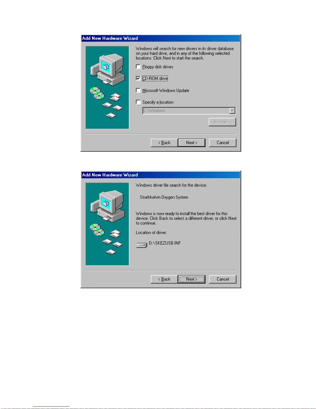
Select Search for the best driver… as shown and click Next to show:
Strathkelvin Instruments }782 User's Guide
9
Tick CD-ROM drive only and click Next to show:
Click Next to install the driver. A final dialog announcing that Windows has finished
installing the driver should appear. Click Finish on this dialog and remove the CDROM
from your computer.

Strathkelvin Instruments }782 User's Guide
10
3.3 Operation
Always switch the meter on before starting the 782 computer program.
When first switched on, the meter initialises its internal program and then displays the
oxygen concentrations using the settings stored when it was switched off. The front
buttons will be operational.
Once the computer program starts running, the meter display will show ‘ONLINE’ and
continue to display the oxygen values for each channel selected on the computer. The
buttons on the meter will cease to operate.
The meter can only be switched off with its panel buttons when it is not under computer
control. This protects against accidental interruption of an experiment. By making the
appropriate selection on the program menus the meter can be made to turn off when the
program is closed down.

Strathkelvin Instruments }782 User's Guide
11
4 782 Oxygen Meter
4.1 Introduction
This chapter describes the setup and running of experiments when the instrument is used
as a stand alone meter i.e. when it is not controlled by a computer. If the meter will always
be used with a computer then the setup and running procedures will be carried out using
the 782 System Software which is described in Chapter 5.
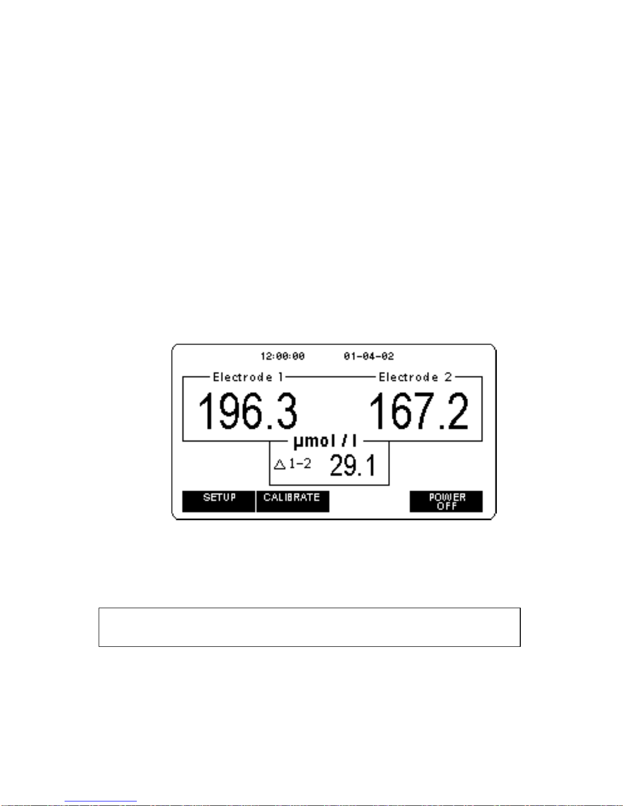
4.2 Setup
When the meter is switched on its display will look similar to that below.
To change to one electrode or to change the units or other settings press the SETUP
button which will bring up this screen:
Strathkelvin Instruments }782 User's Guide
12
To change any of the SETUP options use either the qor pbutton and press the
CHANGE button when the option to be changed is highlighted. You may need to press the
CHANGE button a number of times to go though all the options that can be selected.
SETUP Options
Measure and Display: has three options
Electrode 1 will make measurements from the electrode plugged into Ch
1.
Electrode 1, 2 will make measurements from two electrodes plugged into
Ch1 and Ch2.
Electrodes 1, 2, 1-2will make measurements from two electrodes plugged into
Ch1 and Ch2 and will display the difference between the
readings by subtracting the reading of electrode 2 from that
of electrode 1.
The last option results in this display.
Oxygen Units: You may choose to work in units of µg/ml; mg/l; µl/ml; ml/l;
µmol/l; torr; kPa or %saturation.
Time/date display: ON/OFF
Data Logging: ON/OFF This enables a facility for saving oxygen
measurements to the memory of the meter (see section 4.4)
Note: The Time/date display is set to Windows time/date settings every time the
meter is connected to the PC and the Strathkelvin software is run.

Strathkelvin Instruments }782 User's Guide
13
When Data Logging is selected ON another option will be displayed.
Data logging interval:You may select Manual to save a reading each time the Save
button is pressed, or a time interval to automatically save
values at fixed time intervals. Intervals of 1s, 5s, 10s or 20s
are available. Note that you cannot change between Manual
and Timed intervals unless the data memory is empty.
To exit the SETUP screen, press the Run button.
4.3 Calibrating your Electrodes
The electrodes will normally need to be calibrated every day or when the measurements
units have been changed. If the electrodes have just been connected to the meter, or the
power to the meter has just been turned on, wait one hour to allow the electrode(s) to
stabilise before calibrating. Subsequently, the electrodes can be kept connected to the
meter with the power on ready for immediate use.
During calibration, the meter displays the electrode output in picoamps. This is not used in
the actual calibration procedure but is a useful check on the state of ‘health’ of the
electrodes. See Appendix 8.3.
Before starting your calibration, make sure your calibrating solutions have been prepared
(see Appendix 8.6).
Proceed through the following steps:
1. Set the high point calibration value. If your high-point calibration solution will be air-
saturated water, this will be:
The partial pressure of oxygen, if working in pressure units
or
100 % saturation, if working in percentage saturation units
or
the concentration of oxygen in an air-saturated solution which you will have
obtained from tables (see Appendix 8.7), if using concentration units.
The high point value can be changed by using the qbutton to highlight the High
point value: and then press Change. The meter will then display the following:
Note:
If you have changed the type of membrane (polypropylene, FEP), you must
connec
t the meter to the PC and run the software to change the meter sensitivity.
See Section 5.4.

Strathkelvin Instruments }782 User's Guide
14
The furthest right digit will be flashing, in this case the 0. Use the +or –buttons to
increase or decrease the number. Once it is correct, press the Next digit button
so that the next digit left will flash and repeat the process.
2. The electrodes may be calibrated together or singly. To change the electrode(s)
selected highlight the Electrode: option using the qbutton and keep pressing the
CHANGE button until you have the required option. Press the OK button.
3. Usethepbutton to highlight <<START>> and then press the OK button.
4. The display below will appear, telling you to expose the electrode(s) to the high
point calibration solution. After doing this, press the START button. There is also
an option to CANCEL the calibration at this stage.
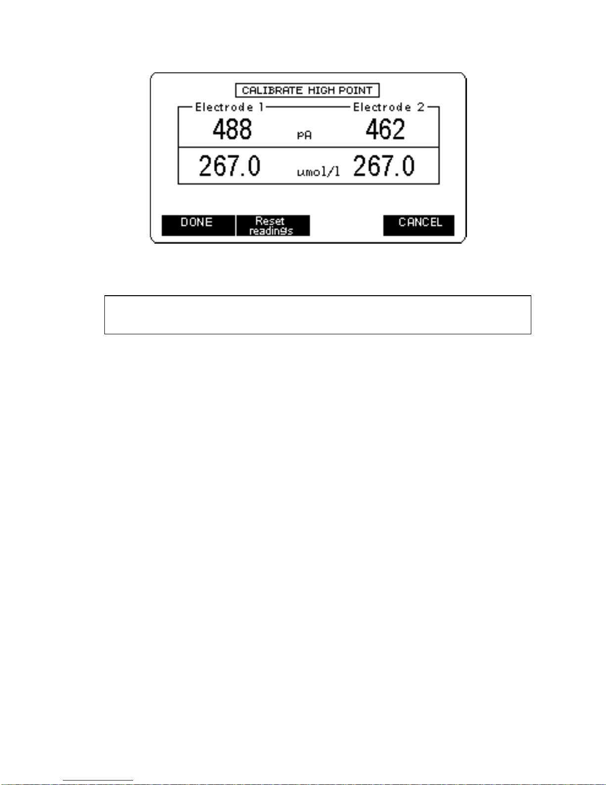
5. You will then be asked to wait while the electrode(s) stabilise. At the end of this one
minute waiting period, the display below will appear.
Strathkelvin Instruments }782 User's Guide
15
6. Press the Reset readings button if any of the values drift away from the high point
value. When the values are stable, press the Done button.
7. The display will now change to CALIBRATE ZERO. Repeat steps 4 to 6, using the
zero oxygen calibrating solution. If the CANCEL button is pressed at this stage the
high point calibration will be saved.
4.4 Data Logging
The data logging facility allows readings to be saved when the meter is not attached to a
computer. The meter can be set up to either take readings at fixed time intervals or to
allow data to be manually saved.
On using the meter for the first time the data logging function will be turned off. To start
data logging press the SETUP button. Use the qbutton to highlight the Data logging:
option. Press the CHANGE button to turn the Data logging ON. Another SETUP option
will now be available titled Data logging interval. Using the down arrow button highlight
the Data logging interval option and press the CHANGE button to go through the options
available. Manual logging or Timed readings at fixed intervals can be selected.
Timed readings
Timed readings are taken at fixed time intervals of 1s, 5s, 10s or 20s. Depending on the
time interval chosen the display will show the amount of logging time remaining at the
current sampling rate (amount of free memory). This will be displayed on the lower right-
hand side of the display under the heading Free.
Note: It is important that you do not remove the electrode(s) from the calibrating solution
before you press the DONE button.

Strathkelvin Instruments }782 User's Guide
16
For each sample interval the total logging time is given below.
Sample Interval
(seconds) Logging Time–1 channel
(hours & minutes) Logging Time –2 channels
(hours & minutes)
1s 4h 32 m 2h 16m
5s 22h 44m 11h 22m
10s 45h 28m 22h 44m
20s 90h 56m 45h 28m
The recorded data may be divided into a number of runs (maximum: 20 runs), a new run
beginning each time the START LOGGING button is pressed. On the lower left-hand side
of the display the run number and the number of readings saved in the run are displayed.
An example of a display is given below showing Run 3 with 40 readings and a Free logging
time of 33 minutes.
To start a logging run, press the START LOGGING button.
The options available will change to SET MARK and STOP LOGGING.
The SET MARK allows a marker to be set in the recording data. If you want to introduce a
substance to the respirometer chamber, you can record this event by inserting an event
marker. You must note manually the information corresponding to the marker as this
cannot entered. The time the marker was set will be up loaded along with the data when
the meter is connected to a computer. A maximum of 8 markers per run may be set. The
SET MARK button label shows the number of the next marker to be stored.
At the end of a run press the STOP LOGGING button. The Run display will increase by
one.
Manual readings
If automatic readings have been saved you will need to up load these and erase the
memory before the manual option can be selected.
Change Data logging interval to the Manual setting.
The display will list the number of readings that can be saved in the lower right hand side
under the heading Free. Before any readings have been saved it will show 3272 when 2

Strathkelvin Instruments }782 User's Guide
17
channels are selected. On the lower left hand side of the display the number saved will be
given under the heading Saved. An example of this display screen is given below.
To save a reading press the SAVE READING button.
To switch off the meter press the POWER OFF button. A screen will display asking you to
confirm power off. If you wish to continue, press the OK button if not press the CANCEL
button.
4.5 Uploading Stored Data from the 782 Meter
Connect the meter to the PC using the USB cable. Start the Strathkelvin software and
press the Upload data button will cause the Upload data from meter dialog to appear. If
no data is available, the dialog will display 'No data stored'. If data is loaded from the meter
the dialog will appear in one of two forms depending on whether the stored data is timed or
manual:
Timed readings
This may consist of a number of runs, each containing samples saved at fixed intervals of
1, 5, 10 or 20s. The time of start of each run and up to 8 event markers are also recorded.
After adding details of the experiment, each run can be saved to disc, to be subsequently
opened by the Analyse part of the Strathkelvin software.
Notes:
1. The memory of the meter can only be erased with the computer program.
2. If manual data is stored, logging will be disabled if the number of channels is changed.
Table of contents


