OHAUS STARTER 2100 User manual

SERVICE MANUAL
STARTER 2100 Bench pH Meter
STARTER 3100 Bench pH Meter
STARTER 3100C Bench pH Meter
The information contained in this manual is believed to be accurate at the time of publication, but
Ohaus Corporation assumes no liability arising from the use or misuse of this material. Reproduction
of this material is strictly prohibited.
Material in this manual is subject to change.

TABLE OF CONTENTS
Page No.
CHAPTER 1 GETTING STARTED
1.1 Introduction..............................................................................................................1-1
1.2 Service Facilities......................................................................................................1-1
1.3 Tools and Test Equipment Required........................................................................1-1
1.4 Specifications...........................................................................................................1-2
1.5 Meter Operation Starter 2100...................................................................................1-3
1.5.1 Overview of the Controls...................................................................................1-3
1.6 Meter Operation Starter 3100...................................................................................1-5
1.6.1 Overview of the Controls...................................................................................1-5
1.7 Meter Operation Starter 3100C................................................................................1-7
1.7.1 Overview of the Controls...................................................................................1-7
CHAPTER 2 MAINTENANCE PROCEDURES
2.1 Preventive Maintenance...........................................................................................2-1
2.2 Service Strategy.......................................................................................................2-1
2.3 Opening the Meter ...................................................................................................2-1
2.2.1 Separating the Top and Bottom Housings.........................................................2-1
2.4 Removing/Replacing the Main Printed Circuit Board (PCB) .....................................2-2
CHAPTER 3 RESET TO FACTORY SETTINGS
3.1. Recover Factory Settings.........................................................................................3-1
CHAPTER 4 DRAWINGS AND PARTS LISTS
4-1 Starter 2100 Scale: Housing & Internal Parts...........................................................4-2
4-2 Starter 3100 Scale: Housing & Internal Parts...........................................................4-3
4-3 Starter 3100C Scale: Housing & Internal Parts.........................................................4-3
LIST OF TABLES
TABLE NO. TITLE Page No.
1-1 Specifications ......................................................................................................1-2
1-2 Starter 2100 Controls Functions ..........................................................................1-4
1-3 Starter 3100 Controls Functions ..........................................................................1-6
1-4 Starter 3100C Controls Functions........................................................................1-8
3-1 Mounting Bolt Torque Settings.............................................................................3-5
3-2 Overload Stop Gap Settings................................................................................3-6
4-1 Housing & Internal Parts......................................................................................4-1
LIST OF ILLUSTRATIONS
FIGURE NO. TITLE
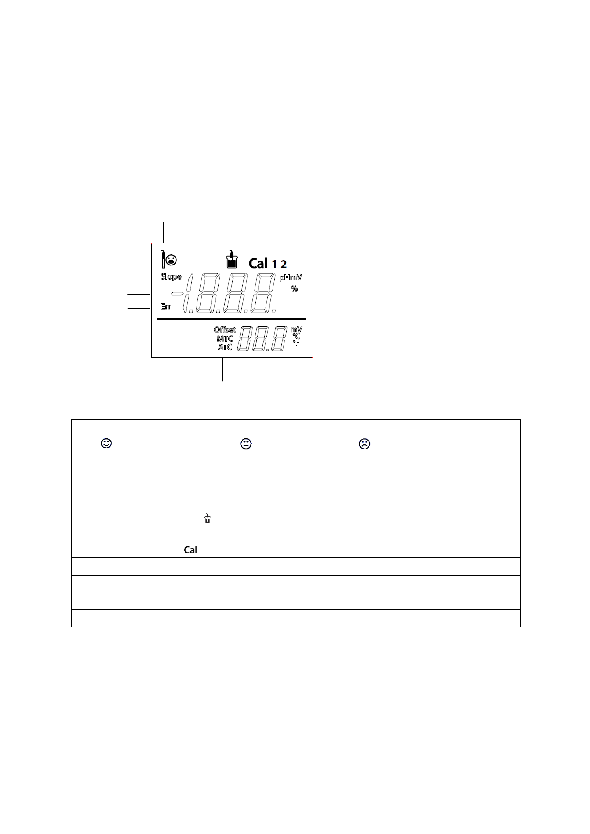
1-1 Starter 2100 Display............................................................................................1-3
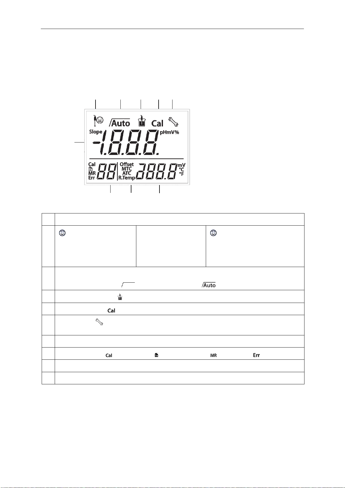
1-2 Starter 3100 Display............................................................................................1-5
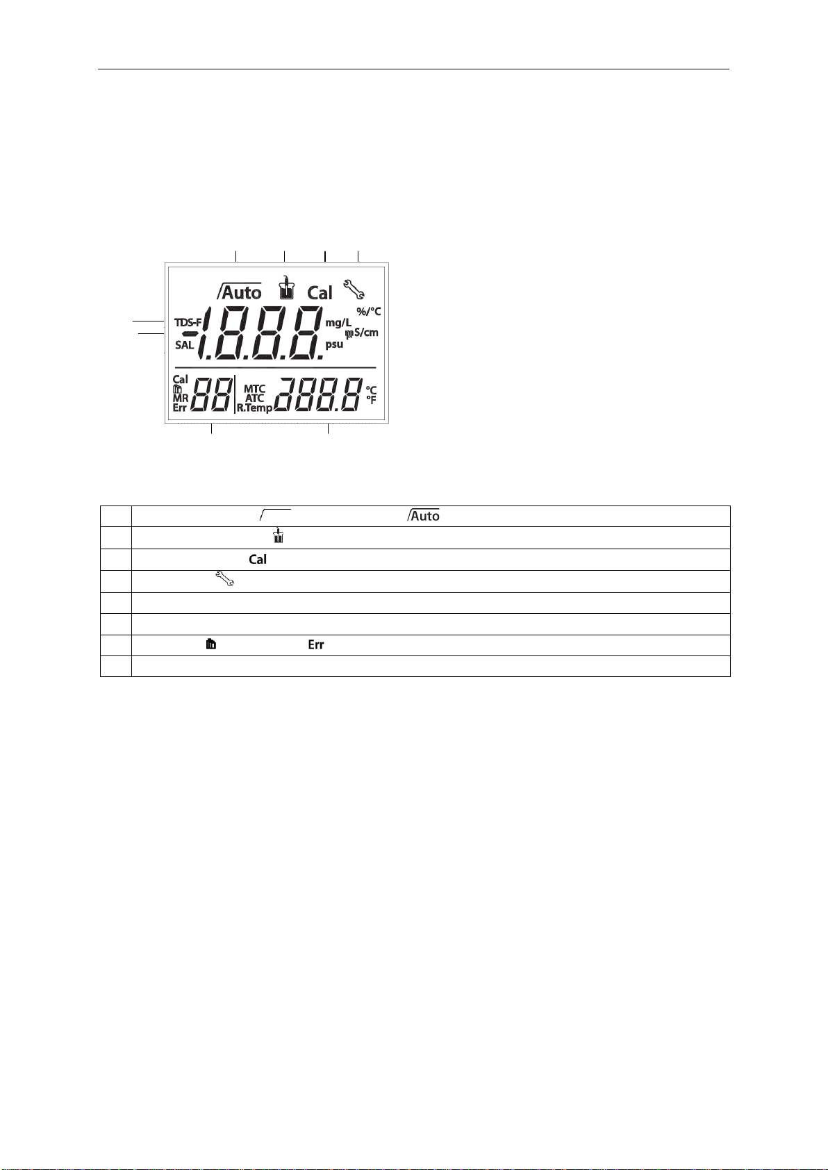
1-3 Starter 3100C Display..........................................................................................1-7
2-1 Screws securing Top Housing .............................................................................2-1
2-2 Main Printed Curcuit Board..................................................................................2-2
4-1 Housing & Internal Parts......................................................................................4-2
4-2 Housing & Internal Parts......................................................................................4-3
4-3 Housing & Internal Parts......................................................................................4-4

CHAPTER 1 GETTING STARTED
1.1 INTRODUCTION
This service manual contains the information needed to perform routine maintenance and
service on the Ohaus Starter 2100, Starter 3100 and Starter 3100C Series meters.
Familiarity with the meter’s Instruction Manual is assumed. The contents of this manual are
contained in five chapters:
Chapter 1 Getting Started –Contains information on service facilities, tools and test
equipment, specifications, and the mechanical and electronic functions of the meter.
Chapter 2 Maintenance Procedures –Contains preventive maintenance procedures and
disassembly, repair and replacement procedures.
Chapter 3 Drawings and Parts Lists –Contains exploded views of Starter
2100/3100/3100C meters identifying all serviceable components.
Chapter 4 Reset to factory settings –Explains procedures for resetting the meter to
factory default settings.
1.2 SERVICE FACILITIES
To service a meter, the service area should meet the following requirements:
Should be temperature controlled and meet meter specifications for temperature
environmental requirements.
Must be free of vibrations such as fork lift trucks close by, large motors, air currents
or drafts from air conditioning/heating ducts, open windows, people walking by, fans,
etc.
Area must be clean and free of excessive dust.
Work surface must be stable and level.
Meter must not be exposed to direct sunlight or radiating heat sources.
Use an approved Electro-Static Device.
1.3 TOOLS AND TEST EQUIPMENT REQUIRED
The service shop should contain the following equipment:
1. Standard hand tools.
2. Digital Voltmeter (DVM).
3. Standard Electronics tool kit.
4. Grounding mat and clip.

CHAPTER 1 GETTING STARTED
1.4 SPECIFICATIONS
Complete specifications for the Ohaus Starter 2100 meters are listed in Table 1-1. When a
meter has been serviced, it must meet the specifications listed in the table. Before servicing
the meter, determine what specifications are not met.
TABLE 1-1. SPECIFICATIONS
Model
Starter 2100
Starter 3100
Starter 3100C
Measuring range
0.00…14.00 pH
–1999…1999 mV
0 °C…100 °C
-2.00…16.00 pH
–1999…1999 mV
-5 °C…110 °C
0.0 μS/cm…199.9 mS/cm
0.1 mg/l…199.9 g/l (TDS)
0.00 ... 19.99 psu (Salinity)
0 °C…100 °C
Resolution
0.01 pH
1 mV
0.1 °C
0.01 pH
1 mV
0.1 °C
Automatic range
0.1 °C
Error limits
±0.01 pH
±1 mV
±0.5 °C
±0.01 pH
±1 mV
±0.5 °C
±0.5 % of the measured value
±0.3 °C
Calibration
1 or 2 points
1 predefined buffer group
(4.01, 7.00, 10.01)
3 points
3 predefined buffer group
1 point
3 predefined standards
Memory
Recall last calibration data
Power supply
110-240V/50Hz, DC 12V
Approximately 220 W x 175 D x 78 H mm / 0.75 kg
Size/weight
Display
Liquid crystal
Input
BNC, impedance > 10e+12 Ω
Cinch, NTC 30 kΩ
Mini-Din
Reference input
2mm banana socket
Temperature-
compensation
ATC & MTC
Linear: 0.00 %/°C…10.00
%/°C
Reference temperature: 20 &
25 °C
Housing
ABS

CHAPTER 1 GETTING STARTED
1.5 METER OPERATION –STARTER 2100
This section contains information on the basic operation of the Starter 2100 meter.
1.5.1 OVERVIEW OF THE CONTROLS
Displays
Figure 1-1. Starter 2100 display
1
Electrode condition
Slope: more than 95%
and offset: ±(0-15) mV
Electrode condition is
good
Slope: 90-95%
or offset: ±(15-35)
mV
Electrode condition is
acceptable
Slope: less than 90%
or offset: ±(35-60) mV
Electrode condition is not good
or needs cleaning
2
Measurement icon - , measurement or calibration is running; disappear means the
reading is locked, no matter measurement
3
Calibration icon - , 1point or 2point calibration in progress
4
pH/mV reading or slope(%) in calibration
5
Error message - Err
6
Auto temperature compensation - ATC ; Manual temperature compensation - MTC
7
Temperature during measurement or Offset (mV) in calibration
2
3
1
4
6
7
5

CHAPTER 1 GETTING STARTED
TABLE 1-2. Control functions Starter 2100
Button
Press & release
Press & hold
for 3 seconds
- Start measurement or lock
current reading
- Confirm temp setting
- Start calibration
- Review the latest calibration
data (slope, offset)
- Meter turn on
- Exit, return to measurement
screen
- Meter turn off
- Entered temperature setup
mode
- Increase temp. value when
in temp. setup mode
- Switch between pH and mV
measuring modes
- Decrease temp. value when
in temp. setup mode
- Start self-diagnosis
Notes: 1Short Press: Press less than 1 seconds.
2Long Press: Press and hold for more than 2 seconds.
3Press and hold the Off button until OFF is displayed, then release the button.

CHAPTER 1 GETTING STARTED
1.6 METER OPERATION –STARTER 3100
This section contains information on the basic operation of the Starter 3100 meter.
1.6.1 OVERVIEW OF THE CONTROLS
Displays
Figure 1-2. Starter 3100 display
1
Electrode condition
Slope: more than 95%
and offset: ±(0-15) mV
Electrode condition is
good
Slope: more than 95%
and offset: ±(0-15) mV
Electrode condition is good
2
Endpoint stability icon ; Auto endpoint icon
3
Measurement icon - ; measurement or calibration is running
4
Calibration icon - ; calibration in progress
5
Setup icon - ; instrument is in the setup mode, can set temperature(MTC), buffer
group etc.
6
pH/mV reading or slope in calibration process
7
Calibration point / Buffer group /Memory number / Error index
8
Auto temperature compensation - ATC ; Manual temperature compensation - MTC
9
Temperature during measurement or offset (mV) in calibration process
2
3
4
1
5
6
7
8
9

CHAPTER 1 GETTING STARTED
TABLE 1-3. Control functions Starter 3100
Button
Press & release
Press & hold
for 3 seconds
- Start or finish measurement
- Confirm setting, store entered value
- Turn auto endpoint on / off
,
- Start calibration
- Recall the latest calibration data : slope
and offset
- Meter turn on
- Exit and return to measurement
screen
- Meter turn off
- Store current reading to memory
- Increase value during setting
- Scroll up through the memory
- Recall stored data
- Print current memory data
- Switch between pH and mV
- Decrease value during setting
- Scroll down through the memory
- Enter setup mode
- Start self-diagnosis
Turn on/turn off the backlight of the LCD

CHAPTER 1 GETTING STARTED
1.7 METER OPERATION –STARTER 3100C
This section contains information on the basic operation of the Starter 3100C meter.
1.7.1 OVERVIEW OF THE CONTROLS
Displays
Figure 1-3. Starter 3100C display
1
Endpoint stability / Auto endpoint
2
Measurement icon - measurement or calibration is running
3
Calibration icon - calibration in progress
4
Setup icon -instrument is in the setup mode
5
TDS factor in the setup mode
6
Conductivity / TDS / Salinity / Cell Constant
7
Standard / Error index
8
Temperature during measurement or reference temperature in setup mode
1
2
3
4
5
7
8
6

CHAPTER 1 GETTING STARTED
TABLE 1-4. Control functions Starter 3100C
Button
Press &
release
Press & hold
for 3 seconds
- Start or endpoint
measurement
- Confirm setting,
store entered value
- Turn auto
endpoint on / off
,
- Start calibration
- Review the
latest calibration
data (cell
constant)
- Meter turn on
- Return to
measurement
screen
- Meter turn off
- Store current
reading to memory
- Increase value
during setting
- Scroll up through
the memory
- Recall stored
data
- Print current
memory data
- Switch between
pH and mV
measuring modes
- Decrease value
during setting
- Scroll down
through the
memory
- Enter setup
mode
- Start self-
diagnosis
Turn on/off the
backlight of the
LCD

CHAPTER 2 MAINTENANCE PROCEDURES
2.1 PREVENTIVE MAINTENANCE
Ohaus meters are precision instruments and should be carefully handled, stored in a clean,
dry, dust-free area, and cleaned periodically.
2.2 SERVICE STRATEGY
All parts of the Starter 2100/3100/3100C are designed to be replaced rather than repaired.
This includes the Main Printed Circuit Board (PCB) and the cables. For an illustrated list of
replaceable parts, see Chapter 5.
2.3 OPENING THE METER
Use these procedures in order to replace the Printed Circuit Board.
2.3.1 Separating the Top and Bottom Housings
Common hand tools are sufficient to disassemble the Starter 21002100/3100/3100C meter.
Turn the meter off and unplug the power cord before you begin.
1. Turn the meter over. Remove the four screws holding the Housing in place.
(See Figure 2-1.)
2. Separate Top Housing from
Bottom Housing. Avoid straining
the cables that connect the Main
PCB on the bottom housing to the
parts in the top Housing. (Lay the
two housings close to each other,
so cable is not strained.)
Figure 2-1. Screws (marked with white
circles) that secure the housing.

CHAPTER 2 MAINTENANCE PROCEDURES
2.4 Removing/Replacing the PCB
If the PCB are suspected of being faulty, it should be replaced, as follows:
1. Disconnect the Cable connecting the PCB to the meter’s control buttons.
(See Figure 3-2.)
2. Remove the four screws that secure the PCB to the bottom housing.
3. Lift out the PCB. (See Figure 3-2.)
4. Position the replacement PCB as in Figure 3-2.
5. Re-connect the Top housing Cable to the PCB, in the same position as originally
installed.
6. Insert and tighten the screws that secure the PCB to the bottom housing.
Figure 2-2. Main Printed Circuit Board with display.
Control buttons
cable connector
4 screws
securing the
PCB

CHAPTER 3 RESET TO FACTORY SETTINGS
3.1 Recover factory settings
When the meter is off, press and hold button-Read & button-Cal & button-Exit together
for 3 seconds, the screen displays and blinks, means “Reset”. Then we have 2
choice:
Press button-Read to reset factory settings (MTC, slope and offset, etc.), display
then restart the meter.
Or press button-Exit to quit the setting, display then turn off the meter.

CHAPTER 4 PARTS LISTS & DIAGRAMS
This section of the manual contains exploded views of the Starter 2100/3100/3100C pH
meter. The exploded view drawings are designed to identify the parts which can be serviced
on the pH meter in the field.
NOTE:
In all cases where a part is replaced, the meter must be thoroughly checked
after the replacement is made. The meter MUST meet the parameters of all
applicable specifications in this manual.
If further technical information is needed, please contact your local Ohaus distributor, or:
www.ohaus.com
Ohaus Corporation,
7 Campus Drive
Suite 310
Parsippany, NJ 07054 USA
Tel: 973-377-9000
Fax: 973-593-0359
In the United States call toll free, 800-526-0659 between 8:00 a.m. and 6:00 p.m. EST.

CHAPTER 4 PARTS LISTS & DIAGRAMS
4.1 STARTER 2100 pH meter: PARTS
Figure 4-1. Starter 2100 pH meter: Parts.
TABLE 4-1 Starter 2100 pH meter: PARTS
Drawing Item
Part Number
Description
1
30063953
SP_Overlay Starter 2100 EN
2
30063907
SP_PCBA Starter 2100
3
30063906
SP_Screw and feet set for Starter Bench
4
30058732
Acc Electrode holder attached
NA
46001724
PWR,W,IN,6W,12VDC,S21x55x9x100,S
NA
46001780
PWR,ACCES,AC-PRONG,SET,EU-US-AU-UK
NA
30063957
ASM Package ST3100
NA
30031622
Manual,Instr.,EN,ST2100
Note:For parts numbers, see your local Ohaus distributor, or visit www.ohaus.com.

CHAPTER 4 PARTS LISTS & DIAGRAMS
4.2 STARTER 3100 pH meter: PARTS
Figure 4-2. Starter 3100 pH meter: Parts.
TABLE 4-2 Starter 3100 pH meter: PARTS
Drawing Item
Part Number
Description
1
30058734
Acc In-use-cover STARTER
2
30063954
SP_Overlay Starter 3100 EN
3
30063908
SP_PCBA Starter 3100
4
30063906
SP_Screw and feet set for Starter Bench
5
30058733
Acc Electrode holder stand alone
NA
46001724
PWR,W,IN,6W,12VDC,S21x55x9x100,S
NA
46001780
PWR,ACCES,AC-PRONG,SET,EU-US-AU-UK
NA
30063957
ASM Package ST3100
NA
30031621
Manual,Instr.,EN,ST3100

CHAPTER 4 PARTS LISTS & DIAGRAMS
4.3 STARTER 3100C pH meter: PARTS
Figure 4-3. Starter 3100C pH meter: Parts.
TABLE 4-3 Starter 3100C pH meter: PARTS
Drawing Item
Part Number
Description
1
30058734
Acc In-use-cover STARTER
2
30063955
SP_Overlay Starter 3100C EN
3
30063909
SP_PCBA Starter 3100C
4
30063906
SP_Screw and feet set for Starter Bench
5
30058733
Acc Electrode holder stand alone
NA
46001724
PWR,W,IN,6W,12VDC,S21x55x9x100,S
NA
46001780
PWR,ACCES,AC-PRONG,SET,EU-US-AU-UK
NA
30063957
ASM Package ST3100
NA
30031623
Manual,Instr.,EN,ST3100C
Test Equipment Depot - 800.517.8431 - 99 Washington Street Melrose, MA 02176
TestEquipmentDepot.com
Other manuals for STARTER 2100
3
This manual suits for next models
2
Table of contents
Other OHAUS Measuring Instrument manuals

OHAUS
OHAUS Defender 2000 Series User manual

OHAUS
OHAUS ST300-B User manual

OHAUS
OHAUS MB35 User manual

OHAUS
OHAUS 5000 User manual

OHAUS
OHAUS CKW Series User manual

OHAUS
OHAUS MC2000 User manual

OHAUS
OHAUS MB23 User manual

OHAUS
OHAUS CKW Use and care manual

OHAUS
OHAUS a-AB23EC User manual

OHAUS
OHAUS 2000 Series User manual