STRATOS SCP7106 User manual

Page 1 of 9
48V Electric PTC Heater
with Permanent Mount
Installation Instructions
SKU: SCP7106
CONTACT:
Phone: (844) 233-4121
Email: info@stratosclimate.com
Website: stratosclimate.com
Mail: 809 110th St, Arlington, TX 76011

Page 2 of 9
02
03
01
04 05
06
H1 H2 H3 H4 H5
H6
PARTS LIST:
Ref. Qty. Part Description
01 1 Heater Assembly
02 1 Wiring Harness
03 1 Switched Power Extension
04 1 Cup Mount
05 1 Tripod Mount
06 1 Nut Plate
Hardware Kit
H1 1 Washer
H2 1 Phillips HD Screw
H3 2 Hex HD Nut
H4 2 Hex HD Bolt
H5 3 Self-Tapping Screw
H6 2 Velcro Tie
SUGGESTED TOOLS:
• Drill
• 5/32” drill bit
• Shor t #2 Phillips screwdriver
• Regular #2 Phillips screwdriver
• Wire cutter

Page 3 of 9
WIRING HARNESS (02) DIAGRAM
Note: Accessory connectors not
used for this installation.

INSTALLATION DIAGRAM
+ -
01
02
03
04
06
H1
05
H2
H5
Page 4 of 9
Page 5 of 9
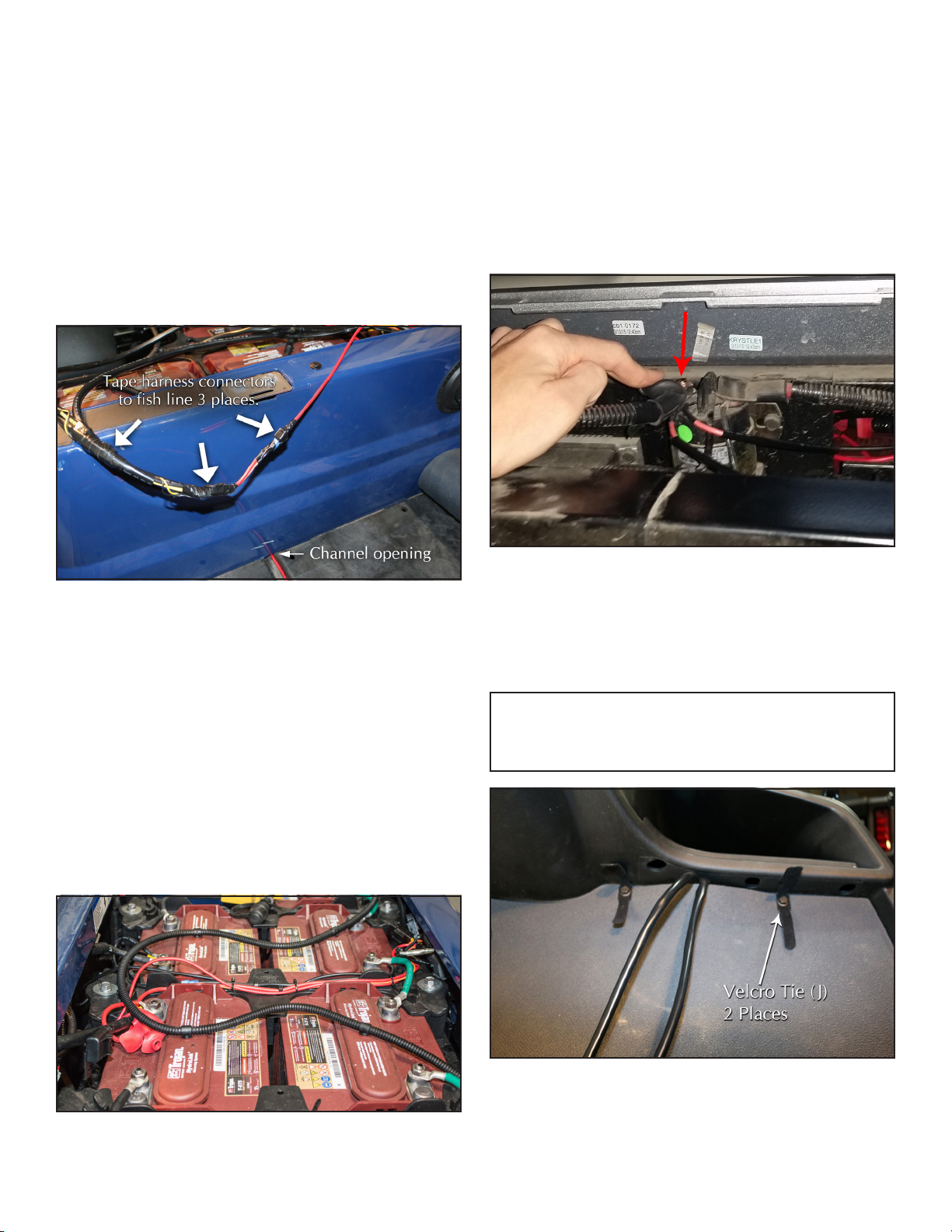
INSTALLATION INSTRUCTIONS
RUN THE WIRING HARNESS
• Run the Wiring Harness (02) from the front
of the vehicle to the battery compartment.
Depending on your vehicle, you may choose to
run the harness through a floorboard channel
or under the vehicle.
• If running through a channel, use a fish line
to help feed the harness into the battery
compartment.
• If running the harness under the vehicle,
secure the harness to the vehicle underside
using cable ties.
CONNECT WIRING HARNESS TO BATTERIES
• To correctly power the heater, attach the
Wiring Harness red wire to the 48V output
terminal having a red wire leading away
from the battery pack, and the black wire
to the 48V ground output terminal having
a black wire leading away from the battery
pack. Refer to your vehicle owners manual
to help determine correct battery terminal
connections if needed.
SWITCHED POWER HOOKUP
• This step will vary depending on your vehicle
model. Locate a switched power connection
and connect using the Switched Power
Extension (03). This is commonly located on
a solenoid in the battery compartment or a
designated accessory terminal behind the
dash. Refer to your vehicle owners manual
to determine ideal switched power hook-up
location.
Above: Example of a switched power terminal located on a
battery compartment solenoid.
MOUNT THE HEATER
• Install Velcro Ties (H6) using existing bolts in
two places as shown.
Note: The Velcro ties are intended to hold the harness
and connectors when not in use. If only one heater will be
installed, an extra connector can be doubled back and
stored under the rubber mat.
• Install preferred Heater Mount (04, 05) to
chosen location.

Page 6 of 9
Note: To install into an existing cup holder, use the
Cup Mount (04). Use the Tripod Mount (05) to install
directly onto the dash.
• Continue for mount installation instructions.
Note: Be sure to leave clearance to allow airflow
between the firewall and heater intake.
• Connect Wiring Harness (02) to back of heater.
TEST HEATER FUNCTION
• Turn on the key switch and test heater
function, ensuring correct harness connection
on driver and passenger side controls.
IF USING THE TRIPOD MOUNT (05)
• Place the Tripod Mount onto the chosen
mounting location and secure with Self
Tapping Screws (H5) in three places. (Note:
After placing the first screw, rotate the mount
clip to access each screw hole as shown).
• Attach Heater to Mount Clip.
IF USING THE CUP MOUNT (04)
• Depress locks on side of Cup Mount & rotate
bottom to disengage teeth.
• Place Cup Mount assembly in dash cup holder.
Insert screw (H2) with washer (H1) & nut plate
(06) through the cup holder’s drain hole. (Do
not tighten).
• Push down Cup Mount top piece to set the
cup mount depth. The lip seal will conform to
the varying dash surface to ensure there are
no gaps. Tighten screw (H2).
• Snap the Heater onto the Mount Clip.

Page 7 of 9
OPERATING GUIDE
The Electric PTC Heater has four modes of
operation with a color-coded LED indicator.
1. Normal “Air Only” Flow (Blue LED)
2. Maximum “Air Only” Flow (Blue LED)
3. Normal Heat (Orange LED)
4. Maximum Heat (Red LED) with 45 Second Hot
Boost.
Note: When in mode 4, the heater will run at maximum
heat and air for 45 seconds and then automatically
switch back to mode 3 to conserve battery. To reset
the power boost, turn knob to mode 3 and back to
mode 4.
BI-LEVEL VENT SYSTEM
The three center fins can be moved to adjust
the air flow direction. Rotating the fins to their
maximum upward position will partially close
the front vent and send air out the side vents,
towards the floor. The side vents are also ideal
for warming your hands.
ELECTRONIC EYE
The Electronic Eye monitors the passenger
compartment and automatically turns off the
heater after 30 seconds of no occupants being
detected.
When in heater modes 3 & 4, the LED indicator
will turn blue after 30 seconds to indicate the
Electric PTC Heater is powering off.
When in air only modes 1 & 2, the fan speed will
slow after 30 second to indicate the heater is
powering off.
The heater will automatically resume when the
Electronic Eye detects a passenger at the last
chosen mode.
BATTERY FAIL-SAFE SENSOR
The heater will automatically power off after
the total battery charge drops below a preset
voltage. This prevents on course battery drain
should you start play without a full battery
charge.
Note: Turn the control knob slowly to allow the
heater’s Power Management Technology to smoothly
transition between operating modes. This will ensure
maximum efficiency with minimum battery drain.

Page 8 of 9
SAFETY
Only operate the heater while module is attached
to its base and securely mounted in the vehicle.
Do not block the heater air intake.
Remove jewelry before hooking up to the
battery to make sure that metal jewelry such as
bracelets and rings do not come in contact with
battery terminals and cause shorting.
This heater is made to be used on 48 Volt vehicles
only. Do not attempt to hookup to a non-48V
vehicle as damage to the heater may occur.
Disclaimer: Many variables can affect the
driving range of the 48V electric vehicle
including ambient temperature, terrain, driving
conditions, payload, driving habits, battery age
and tire pressure.
A vehicle enclosure is recommended for maxi-
mum heater performance and efficiency.
WARNINGS
Do not drop or submerge the heater in water or
liquid.
Do not block the heater air intake.
Shorting across battery terminals may cause
battery explosion.
MAINTENANCE
Periodically check Electronic Eye lens for
smudges or debris and gently wipe clean with a
microfiber cloth. Contamination of the Electronic
Eye lens can impede its ability to accurately
detect occupants in the vehicle cabin.
Regularly check and maintenance the vehicle’s
batteries as instructed in your owner’s
manual. READ ALL WARNINGS AND SAFETY
PRECAUTIONS IN VEHICLE OWNER’S MANUAL
BEFORE SERVICING VEHICLE.
TROUBLESHOOTING
Make sure the vehicle’s batteries are fully
charged. The Battery Fail-Safe Sensor prevents
the heater from powering on if the total battery
charge drops below a preset voltage.
Many factors can affect the battery charge
including age, condition, ambient temperature,
and electrolyte levels.
Note: One or more bad batteries with low voltage can
cause the fail-safe sensor to activate and prevent the
heater from powering on.
If you are having trouble powering on the heater,
ensure that the control knob is in the “Off”
position when starting the vehicle, and that
you gradually (slowly) turn the knob between
modes. This is a power saving feature to prevent
amperage spikes that can occur when instantly
switching to maximum heat.
BATTERY REFERENCE GUIDE
To correctly power the heater, attach the Red
Wire to the 48V output terminal having a red
wire leading away from the battery pack,
and the Black Wire to the 48V ground output
terminal having a black wire leading away from
the battery pack.

Page 9 of 9
ELECTRIC PTC HEATER TWO-YEAR
LIMITED WARRANTY
TSI Products, Inc./Stratos Climate are
warranted to the original retail purchaser,
to be free from defects in materials and
workmanship except as otherwise provided
herein. This warranty is not transferrable
and is effective from the date of the
original purchase.
This Warranty Covers:
1. During the first year from the original
retail purchase date, TSI Products/
Stratos Climate will, at its option,
repair or replace defective components,
including labor and cost of shipment to
original consumer.
2. After the first year from original
retail purchase date, up to the term
of the warranty, TSI Products/Stratos
Climate will repair or replace defective
components with an identical or
reasonably equivalent new component
for a $5.00 service charge which includes
labor and cost of shipment to the
original consumer.
This Warranty Does Not Cover:
1. Cost of shipping the product to TSI
Products/Stratos Climate.
2. Normal wear, scratches or fading of the
product.
3. Damage caused by abuse, misuse,
neglecting to follow use procedures,
failure to follow installation procedures
or product modifications made by
consumer.
4. Damage to home or vehicle electrical
system or components caused by
inadequate wiring to the product plug-
in point.
5. Damage to any object placed close to
the air output of the heater.
6. Damage caused by dropping of heater.
7. Product sold outside the USA.
8. Consequential damages, incidental
damages or expenses, including
damages to property. Some states do
not allow the exclusion or limitation of
incidental or consequential damages, so
above limitation or exclusion may not
apply to you.
Procedures for Warranty service:
1. Contact TSI Products/Stratos Climate
(844-233-4121) for a return authorization
number. Write this number on the
carton being returned to TSI Products/
Stratos Climate.
2. Attach, to the product itself, a tag
showing your name, address, phone
number, description of the problem
and proof of retail purchase date.
Enclose a cashier’s check, check, Visa or
MasterCard information or money order
for applicable service charges.
3. Package the product carefully to ensure
that no damage occurs during return
shipment. Return the product, postage
prepaid, to TSI Products/Stratos Climate.
Implied Warranty:
This warranty is limited to the provisions
clearly stated herein. Any implied
warranties, warranties of merchantability,
warranties of fitness for a particular use are
excluded.
If any provision of this warranty is
prohibited by federal, state, or local law,
that provision shall not be applicable.
Table of contents
Other STRATOS Heater manuals

Popular Heater manuals by other brands


Mars
Mars Comfort-Aire Century HG Series Installation, operation & maintenance instructions

STIEBEL ELTRON
STIEBEL ELTRON CNS 50 TREND Operation and installation guide

Listo
Listo CHSB L3 user guide

S&P
S&P EMIDRY-D Installation manual and instructions for use

Metro DataVac
Metro DataVac C5 1 Series user manual

Viessmann
Viessmann VITOPLANAR EI6 installation instructions


