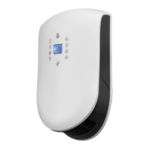
S&P EMIDRY-D User manual

1
EMIDRY-D
Emisor de Calor Seco
Dry Heat Radiator
Radiateur à Inertie Sans Fluide
Emissor de Calor Seco
Manual de instalación. Instrucciones de uso
Installation manual. Instructions for use
Manuel d'installation. Conseils d'utilisation
Manual de instalação. Instruções de uso

2
Fig. 1
Fig. 2
Fig. 3
Fig. 4
Fig. 5
Potencia
Power
Puissance
Potência
500
W
750
W
1.000
W
1.250
W
1.500
W
Nº
Elementos
Fins
Elements
4
6
8
10
12
A
160
320
480
640
800

3
ÍNDICE
1. GENERALIDADES . . . . . . . . . . . . . . . . . . . . . . . . . . . . . . . . . . . . . . . . . . . . . . .4
2. ADVERTENCIAS DE SEGURIDAD E INSTALACIÓN . . . . . . . . . . . . . . . . . . . . .4
3. SELECCIÓN DE EMPLAZAMIENTO . . . . . . . . . . . . . . . . . . . . . . . . . . . . . . . . .5
4. FIJACIÓN A LA PARED . . . . . . . . . . . . . . . . . . . . . . . . . . . . . . . . . . . . . . . . . . .5
5. CONEXIÓN ELÉCTRICA . . . . . . . . . . . . . . . . . . . . . . . . . . . . . . . . . . . . . . . . . .5
6. CONEXIÓN DOMÓTICA . . . . . . . . . . . . . . . . . . . . . . . . . . . . . . . . . . . . . . . . . .6
7. MANDOS Y FUNCIONES . . . . . . . . . . . . . . . . . . . . . . . . . . . . . . . . . . . . . . . . .7
8. OPERATIVA MANUAL . . . . . . . . . . . . . . . . . . . . . . . . . . . . . . . . . . . . . . . . . . . .7
9. OPERATIVA POR HILO PILOTO . . . . . . . . . . . . . . . . . . . . . . . . . . . . . . . . . . .10
10. DESCONEXIÓN GENERAL DEL APARATO . . . . . . . . . . . . . . . . . . . . . . . . .10
11. SI SE PRODUCE UN CORTE DE ELECTRICIDAD . . . . . . . . . . . . . . . . . . . .10
12. PROTECCIÓN DE SOBRECALENTAMIENTO. . . . . . . . . . . . . . . . . . . . . . . .10
13. MANTENIMIENTO PERIÓDICO . . . . . . . . . . . . . . . . . . . . . . . . . . . . . . . . . .11
14. EN CASO DE AVERÍA . . . . . . . . . . . . . . . . . . . . . . . . . . . . . . . . . . . . . . . . . .11
15. PUESTA FUERA DE SERVICIO Y RECICLAJE . . . . . . . . . . . . . . . . . . . . . . .12
ESPAÑOL

4
1. GENERALIDADES
Le agradecemos la confianza que nos ha depositado mediante la compra de este
radiador. Usted ha adquirido un producto de calidad que ha sido totalmente fabri-
cado según las reglas técnicas de seguridad reconocidas y conformes a las nor-
mas de la CE.
Sírvase leer atentamente estas instrucciones, antes de la instalación y puesta en
funcionamiento, posteriormente guárdelas para futuras referencias.
Rogamos compruebe el perfecto estado y funcionamiento del aparato al desem-
balarlo ya que cualquier defecto de origen que presente, está amparado por la
garantía S&P.
2. ADVERTENCIAS DE SEGURIDAD E INSTALACIÓN
- La garantía no cubre los daños que pueda sufrir el aparato en caso de no res-
petar lo indicado en este Manual de Instrucciones.
- Comprobar que la tensión de la red eléctrica corresponde con la indicada en la
placa de características.
- El uso de radiadores eléctricos está prohibido en presencia de gases, explosi-
vos o productos inflamables.
- Ni el cable de conexión ni otros objetos deben entrar en contacto con el aparato.
- No cubrir el aparato con ropa para secar ni con ningún otro objeto.
- Las superficies del emisor pueden estar calientes. Los niños pequeños deber
ser vigilados cuando estén en sus proximidades.
- No instalar nunca el aparato debajo de una toma de corriente eléctrica.
- Cualquier intervención que se haga en el interior del aparato debe realizarse con
la corriente eléctrica desconectada.
- Si la manguera de conexión de esta unidad se encuentra dañada, deberá ser
sustituida a fin de evitar un peligro, por un instalador autorizado, ya que se nece-
sitan herramientas especiales.
- Para evitar sobrecalentamientos, no cubrir el aparato de calefacción.
- Este aparato no está destinado para ser usado por personas (incluidos niños)
cuyas capacidades físicas, sensoriales o mentales estén reducidas, o carezcan
de experiencia o conocimiento, salvo si han tenido supervisión o instrucciones
relativas al uso del aparato por una persona responsable de su seguridad.
- Los niños deberán ser supervisados para asegurar que no juegan con el aparato.
- Estos aparatos (CLASE II / IP24) pueden ser instalados en el volumen 2 del cuar-
to de baño siempre y cuando el aparato esté protegido por un dispositivo diferen-
cial de alta sensibilidad de 30mA. En ningún caso en los volúmenes 0 y 1. (Ver
figura 5) En el cuarto de baño el aparato debe situarse de tal manera que los man-
dos no puedan ser tocados por una persona que esté utilizando la bañera o
ducha.
NOTA: Algunos componentes, como barnices, lubricantes, resinas, etc..., que
intervienen en la fabricación de este aparato, pueden producir cierto olor al ser
conectados por primera vez. Esta circunstancia es normal, no tiene ninguna otra
consecuencia y desaparece totalmente en las primeras horas de utilización.
5
3. SELECCIÓN DE EMPLAZAMIENTO
Debemos elegir una pared en la que se pueda disponer de un espacio sin mue-
bles para situar el aparato. También deberemos evitar objetos en su entorno pró-
ximo como muebles, cortinas u otros aparatos.
En el cuarto de baño el aparato debe situarse de tal manera que los mandos no
puedan ser tocados por una persona que esté utilizando la bañera o ducha. (Ver
Fig.5)
4. FIJACIÓN A LA PARED
Una vez elegido el emplazamiento deberemos proceder como sigue:
- Posicionarlo en su sitio. Para ello sugerimos la utilización de dos parejas de cal-
ces triangulares (Figura 1), pero pueden servir cualquier otro objeto como libros,
papeles, cajitas de cartón, etc... (Figura 2). En todo caso deben respetarse unas
mínimas distancias como se indica en el dibujo figura 1.
Una vez posicionado el emisor deberemos señalar su situación. Para ello nos ser-
viremos de dos trozos de cinta adhesiva que deberemos pegar a la pared según
se indica en la figura 2. Ahora podemos retirar el aparato.
- A partir de este punto deberemos marcar los agujeros superiores de amarre
según la figura 3. Taladrar los agujeros de diámetro 6x30. Meter los tacos y suje-
tar los soportes superiores. Colgar el aparato y después de nivelado apretar fir-
memente estos soportes. Seguidamente posicionar el soporte inferior en su parte
trasera en una de las ranuras centrales, marcar, perforar, meter los tacos y fijar el
soporte (Figura 4).
5. CONEXIÓN ELÉCTRICA
ATENCIÓN
Cuando dentro de una misma instalación de calefacción EMIDRY concurran 2 ó
más emisores interconectados por hilo domótico, los cables de conexión de los
aparatos deben conectarse a la red eléctrica en la misma fase y en su orden, no
respetar esta condición puede provocar un cortocircuito:
Marrón: Fase
Azul: Neutro
Negro: Hilo domótico
Para que los aparatos EMIDRY funcionen satisfactoriamente y sin presentar nin-
gún problema, es necesario realizar una correcta conexión eléctrica. Ésta es
sumamente sencilla pero hay que respetar ciertas condiciones.

6
En primer lugar deberemos disponer de una instalación eléctrica, que se corres-
ponda con el voltaje indicado en el aparato, que cumpla con toda la legislación
vigente y tener contratada la potencia necesaria para conectar todos los apara-
tos.
Este aparato está destinado a ser conectado de forma permanente a una instala-
ción fija. El circuito de alimentación del emisor debe contar con un interruptor de
corte omnipolar con una separación de contactos de al menos 3 m/m.
Varios aparatos pueden estar protegidos por un magnetotérmico común, pero
respetando siempre que la suma de las intensidades de los aparatos, cualesquie-
ra que sean, conectados simultáneamente a cada protector magnetotérmico, no
pueda superar la capacidad de éste. A estos efectos y a los de sección de cable
necesario se indica a continuación la intensidad que se corresponde con la
potencia y tensión nominales:
500 W: 2,2 A 1000W:4,3 A
750 W: 3,3 A 1250 W: 5,4 A
1500 W: 6,5 A
Si la manguera de conexión de esta unidad sufriera algún daño, deberá ser
sustituida, a fin de evitar un peligro, por un instalador autorizado, ya que se
necesitan herramientas especiales.
Todos los cables internos, conductores, tierra e hilo domótico son de 1mm de
sección.
6. CONEXIÓN DOMÓTICA
Los emisores disponen además del cable de fase y de neutro, de un cable adicio-
nal color negro (cable piloto de domótica).
Los aparatos EMIDRY están preparados para recibir una señal domótica sistema
Gifam. Para realizar este control es necesario conectar entre sí los cables negros
de todos los aparatos que van a configurar la instalación de calefacción y desde
cualquier punto de esta interconexión conectarla a su vez a la central domótica.
El orden de conexión es irrelevante y lo mismo pueden ir todos a un punto que
pasar un cable en serie de uno a otro o mezclar ambas formas. La única condi-
ción es que estén todos los cables negros conectados entre sí y con la central
domótica.
Por este cable va a pasar tensión de diferente voltaje (máx. 230 V~) pero con muy
baja intensidad.
Recomendamos utilizar cable negro aislado y de la misma sección que el resto de
la instalación. La conexión entre cables debe hacerse con regletas de una vía del
tipo que corresponda a la sección del cable.

7
Si uno, varios o todos los aparatos no queremos interrelacionarlos, el cable negro
de ese o esos aparatos deberá quedar sin conectar y con la punta conveniente-
mente aislada.
7. MANDOS Y FUNCIONES
8. OPERATIVA MANUAL
8.1 Conexión del aparato
Conectar el interruptor ON/OFF situado en la parte posterior del cabezal de man-
dos (indicación roja a la vista).
Una vez conectado el interruptor en ON el display mostrará la temperatura
ambiente.
Podrá mostrar encendidos o apagados tanto los puntos del display como los pilo-
tos luminosos.
8.2 Selección de funcionamiento
Si el aparato no tiene encendido el punto ON, el aparato se encuentra en
(Standby). Pulsando la tecla central ordenamos el modo .
El display indicará la temperatura ambiente con luz tenue y aparecerá un punto
situado en la esquina inferior derecha que indica que el aparato está en ON.
· Aparato calentando
· Modo activado
· Timer activado
· Aparato en ON
· Disminuir
Función Timer
· Modo:
· Indicador de temperaturas
· Indicador AH (anti - hielo)
· Indicador de tiempo
(al programar el Timer)
· Aumentar
· Función límite de consigna

8
Calentará si la consigna es más alta que la temperatura ambiente.
Pulsando de nuevo la tecla , el emisor pasa a modo . Se iluminará el pilo-
to azul para indicarlo.
Calentará si la consigna esta al menos 3,5ºC más alta que la temperatura ambiente.
Manteniendo pulsada la tecla central durante 2 segundos, el aparato pasará
a modo “stand-by” (aparato en paro).
Desaparecerá la indicación ON del display (punto fijo en la esquina inferior dere-
cha) y el aparato seguirá indicando la temperatura ambiente de la estancia.
8.3 Selección de temperatura
Para seleccionar la temperatura deseada pulsar cualquiera de las
teclas ó , se iluminará totalmente el display y a cada pulsación siguiente
en ó en la temperatura de consigna aumenta o disminuye 1Cº respectiva-
mente.
Transcurridos 5 segundos sin pulsar ninguna tecla la pantalla pasará a brillar de
forma tenue y a mostrar la temperatura ambiente de nuevo.
8.4 Función Anti Hielo
Pulsar la tecla menos hasta el punto inferior.
La pantalla mostrará la indicación AH (Anti hielo) según se indica:
Con esta función activada el aparato se conectará cuando la temperatura des-
cienda a 5ºC, manteniendo la estancia entre 5ºC y 6ºC.
8.5. Limitación de temperatura máxima.
Aunque el termostato tiene un campo de regulación entre +5ºC y +35ºC, se
puede limitar este campo reduciendo la temperatura máxima consignable hasta
+15ºC, es decir, se puede reducir el campo hasta dejarlo entre +5ºC y +15ºC.
Esta selección tiene un nivel de acceso restringido puesto que es necesario
conocer el procedimiento. Proceder de la siguiente manera:
1º. Mantener pulsado durante 2 segundos. Aparecerá parpadeando en la pan-
talla la limitación de la temperatura máxima seleccionada (35ºC por defecto).
2º. Pulsar y para ajustar la limitación que se desee fijar. A cada pulsación
se corresponde el incremento o el decremento respectivo de 1ºC. Transcurridos
5 segundos sin pulsar estas teclas, se acepta el valor y pasa a pantalla normal.
Siempre
Cuando
corresponde

8.6 Función Timer
Esta función permite programar bien una parada, o bien una puesta en marcha
del aparato en una selección de hasta 99 horas. Hasta 9 horas y 45 minutos la
selección se realiza en fracciones de 15 minutos, y a partir de 10 horas hasta 99
horas en fracciones de 1 hora.
Esta función permite en unos casos mantener el aparato en funcionamiento
durante un tiempo determinado, por ejemplo, cuando nos vamos a la cama y en
otros casos conectar el aparato con la antelación que queramos antes de levan-
tarnos. También permite conectar el aparato antes de que regresemos tras una
ausencia que puede llegar a ser de todo un fin de semana.
Para activar esta función:
1º Mantener pulsado durante 2 segundos.
Aparece en la pantalla “0 ” y el punto superior izquierdo parpadeando.
2º Pulsando y se selecciona el tiempo que se desea fijar.
Para las fracciones de cuarto de hora (hasta 9h 45’) cada línea horizontal simbo-
liza un cuarto de hora más a añadir al digito de la izquierda, de forma que:
1 línea horizontal simboliza 15 minutos
2 líneas simbolizan 30 minutos
3 líneas simbolizan 45 minutos
A partir de 10 horas, cada pulsación equivale a una hora.
Transcurridos 5 segundos sin pulsar las teclas queda aceptada la programación,
la pantalla vuelve a marcar la temperatura ambiente, el punto parpadea y el reloj
comienza la cuenta atrás.
3º Una vez consumido el tiempo programado automáticamente realizará una de
estas dos maniobras:
Si el aparato está en (paro) se pondrá en .
Si el aparato está en , ó , se parará y quedara en .
9
Parpadeando
ejemplo 6h y 3/4
Cuando
corresponde

10
9. OPERATIVA POR HILO PILOTO
Los emisores EMIDRY-D conectados a un hilo domótico están preparados para
recibir de forma automática las órdenes de una central domótica.
Para que las ordenes domóticas sean ejecutadas correctamente y todas ellas sin
restricciones, el aparato debe estar en modo .
Si el aparato estuviera en modo atenderá todos los modos recibidos,
salvo que se ejecutará como .
Si el aparato esta en ejecutará todas las señales como , salvo (paro)
que la cumplirá.
Con el aparato en (paro) no atenderá ninguna señal domótica.
Por último, si la selección manual fuera (paro), el aparato no atenderá ningu-
na señal domótica.
En ausencia de señal domótica el aparato ejecutará la selección manual que reciba.
10. DESCONEXIÓN GENERAL DEL APARATO
El aparato en posición de (paro) no está desconectado de la corriente eléc-
trica.
En este caso, los datos de temperatura y de Timer (si esta activado) se mostra-
rán en pantalla.
En prolongados periodos sin usar el aparato (verano, vacaciones, etc) se reco-
mienda desconectar totalmente el aparato.
Para hacer esta desconexión es necesario pulsar el interruptor mecánico situado
en la parte posterior del cabezal de mandos. La indicación roja deberá quedar
oculta.
En esta posición el display queda totalmente apagado sin ninguna información.
No obstante se mantienen almacenadas todas las selecciones de modo, tempe-
ratura de consigna y de limitación de temperatura máxima.
11. SI SE PRODUCE UN CORTE DE ELECTRICIDAD.
El aparato quedará fuera de servicio y volverá a conectarse cuando se restablez-
ca el suministro eléctrico. Todas las selecciones se mantienen sin sufrir ninguna
modificación. La función Timer se cancelará.
12. PROTECCIÓN DE SOBRECALENTAMIENTO.
El aparato está concebido para que transmita el calor por convección y por radia-
ción. Esta función quedaría dificultada si el aparato se cubre total o parcialmen-
te con ropas húmedas o secas, o con cualquier otro objeto. Además provocaría
un sobrecalentamiento del mismo.

11
No obstante, el aparato cuenta con un dispositivo de seguridad que actúa des-
conectándolo, si se produce un sobrecalentamiento.
El aparato entra automáticamente en funcionamiento una vez corregida la ano-
malía.
Además de afectar negativamente al servicio de forma ocasional, su repetición
puede ser causa de una avería que no quedaría cubierta por la garantía.
13. MANTENIMIENTO PERIÓDICO
No es preciso realizar ningún tipo de mantenimiento periódico de tipo técnico.
Sólo es necesaria una limpieza cada cierto tiempo, la cual puede hacerse con
aspirador, acoplándole un cepillo suave. También puede pasarse simplemente un
paño húmedo con agua, o bien con un jabón neutro para quitar machas acciden-
tales.
14. EN CASO DE AVERÍA
1. Compruebe que el interruptor ON/OFF esta conectado (indicación roja a la
vista)
2. Compruebe que llega corriente al aparato (piloto o señal indicadora)
3. Compruebe que la temperatura de consigna en modo está por encima de
la temperatura ambiente.
Una vez realizadas estas comprobaciones sin encontrar una justificación, recurrir
al Servicio de Asistencia Técnica.
Para aclarar cualquier duda con respecto a los productos S&P diríjase a la Red
de Servicios Post Venta si es en territorio español, o a su distribuidor habitual en
el resto del mundo. Para su localización puede consultar la página WEB
www.solerpalau.com

12
15. PUESTA FUERA DE SERVICIO Y RECICLAJE
- En caso de puesta en fuera de servicio, aunque sea de forma temporal, es
aconsejable conservar el aparato en lugar seco y libre de polvo, dentro de su
embalaje original.
- La normativa de la CEE y el compromiso que debemos adquirir con las futuras
generaciones, nos obligan al reciclado de materiales; le rogamos que no olvide
depositar todos los elementos sobrantes del embalaje en los correspondientes
contenedores de reciclaje, así como de llevar los aparatos sustituidos al Gestor
de Residuos más próximo.
EL FABRICANTE NO SE HACE RESPONSABLE DE LOS DAÑOS PRODUCIDOS
A PERSONAS Y/O COSAS DEBIDOS AL INCUMPLIMIENTO DE ESTAS ADVER-
TENCIAS.
S&P SE RESERVA EL DERECHO A MODIFICACIONES DEL PRODUCTO SIN
PREVIO AVISO.

13
ENGLISH
INDEX
1. INTRODUCTION . . . . . . . . . . . . . . . . . . . . . . . . . . . . . . . . . . . . . . . . . . . . . . .14
2. SAFETY PRECAUTIONS . . . . . . . . . . . . . . . . . . . . . . . . . . . . . . . . . . . . . . . . .14
3. WHERE TO INSTALL THE RADIATOR . . . . . . . . . . . . . . . . . . . . . . . . . . . . . .14
4. MOUNTING THE RADIATOR ON THE WALL . . . . . . . . . . . . . . . . . . . . . . . . .15
5. ELECTRICAL CONNECTION . . . . . . . . . . . . . . . . . . . . . . . . . . . . . . . . . . . . .15
6. HOME AUTOMATION CONNECTION . . . . . . . . . . . . . . . . . . . . . . . . . . . . . . .16
7. CONTROLS AND FUNCTIONS . . . . . . . . . . . . . . . . . . . . . . . . . . . . . . . . . . . .16
8. MANUAL OPERATION . . . . . . . . . . . . . . . . . . . . . . . . . . . . . . . . . . . . . . . . . .17
9. OPERATION AS PART OF A HOME AUTOMATION NETWORK . . . . . . . . . .19
10. DISCONNECTING THE APPLIANCE FROM THE POWER SUPPLY . . . . . .19
11. IN THE EVENT OF POWER OUTAGE . . . . . . . . . . . . . . . . . . . . . . . . . . . . . .19
12. OVERHEATING PROTECTION. . . . . . . . . . . . . . . . . . . . . . . . . . . . . . . . . . . .19
13. PERIODICAL MAINTENANCE . . . . . . . . . . . . . . . . . . . . . . . . . . . . . . . . . . . .20
14. IN THE EVENT OF BREAKDOWN . . . . . . . . . . . . . . . . . . . . . . . . . . . . . . . . .20
15. REMOVAL FROM SERVICE, DISPOSAL AND RECYCLING . . . . . . . . . . . .20

14
1. INTRODUCTION
Thank you for purchasing one of our radiators. You have purchased a high-quality
product manufactured in full compliance with applicable safety regulations and
with EU standards.
Please read these instructions carefully before installing and switching on the
radiator. Keep these instructions in a safe place for future reference.
Please check that the appliance is in perfect condition when you unpack it, as all
factory defects are covered by the S&P guarantee.
2. SAFETY PRECAUTIONS
- The guarantee does not cover any damage sustained by the appliance as a
result of the failure to follow the indications given in this Instructions Manual.-
Check that the mains voltage matches the voltage indicated on the appliance's
specifications plate.- Electric radiators may not be used in the presence of gases,
explosives or flammable materials.- No objects, including the connector cable,
should enter into contact with the appliance.- Do not cover the appliance or use
it for drying clothes.- Surfaces of the heater may become very hot. Small children
should be kept under supervision when near the appliance.- Never install the
appliance beneath a power socket.- Always isolate the power before removing the
cover of the appliance.- If the power cable is damaged it should be replaced by
an authorized installer, as such an operation requires special tools.- To avoid over-
heating, do not cover the appliance.- This appliance is not suitable for use by per-
sons (including children) whose physical, sensorial or mental capacities are impai-
red, or who lack the appropriate experience and knowledge necessary for its use,
unless acting under the supervision or instructions of a person responsible for
their safety.- Children should be kept under supervision to ensure they do not play
with the appliance.
- This appliance (CLASS II / IP24) may be installed in bathrooms zone 2 on con-
dition that it is fitted with a high-sensitivity 30mA residual current device. Under
no circumstances should the appliance be installed in zones 0 or 1. (See figure 5)
When installed in a bathroom, the appliance should be located in such a position
that its controls cannot be reached by persons using the bath or shower.
NOTE: Certain products used in the manufacture of this appliance (paints, lubri-
cants, resins etc.) may give off a certain odour when the appliance is connected
for the first time. This phenomenon is perfectly normal and harmless, and disap-
pears totally after a few hours of use.
3. WHERE TO INSTALL THE RADIATOR
The appliance should be wall mounted in a place unobstructed by furniture. Avoid
installing the appliance in a place where it is likely to be obstructed by other
objects such as furniture, curtains or other appliances.When installing in a bath-
room, position the appliance in such a way that its controls cannot be reached by
persons using the bath or shower. (See fig. 5)

15
4. MOUNTING THE RADIATOR ON THE WALL
Once a suitable installation point has been selected, proceed as follows:- Position
the appliance in its place of installation. To do this, we recommend using two pairs
of triangular wedges (Figure 1), although any other suitable objects such as
books, papers, cardboard boxes etc. can also be used (Figure 2). Always obser-
ve the minimum clearance dimensions as indicated in Figure 1.
Once the appliance is correctly positioned, mark its position on the wall using two
strips of adhesive tape applied to the wall as shown in figure 2. The appliance can
now be removed for the moment.
- Now mark the upper drill holes as shown in figure 3. Drill holes of diameter 6 x
30 mm. Insert the wall plugs in the drill holes and screw in the upper brackets.
Hang the appliance from the brackets, level properly and then tighten the brac-
kets until firmly in place. Now position the lower bracket behind the heater, mark,
drill, insert wall plugs and fix the bracket in place (figure 4).
5. ELECTRICAL CONNECTION
IMPORTANT
In situations where the same EMIDRY heating installation comprises 2 or more
heaters interconnected as part of a home automation network, the power cables
of each appliance should be connected to the mains supply in the same phase
and in the correct order. Failure to do so may cause a short circuit:
Brown: Live
Blue: Neutral
Black: Home automation network
EMIDRY appliances must be correctly wired if they are to function properly and
without problems. Wiring is perfectly simple, but certain conditions must be res-
pected. First of all, the mains supply must be compatible with the voltage indica-
ted on the appliance; it should be in compliance with all applicable regulations
and should have the necessary power rating for connecting all appliances. This
appliance is designed to be permanently connected to a fixed installation. The
heater's power circuit should incorporate an omnipolar circuit breaker with at least
3 mm separating the contacts. Various appliances can be protected by the same
circuit breaker, on condition that the sum of the currents of the appliances con-
nected to each circuit breaker does not exceed the latter's capacity. For the above
purposes (and for purposes of necessary wire sections) we indicate below the
amperages corresponding to the power ratings:
500 W: 2,2 A 1000W:4,3 A
750 W: 3,3 A 1250 W: 5,4 A
1500 W: 6,5 A

16
If the appliance's power cable is in any way damaged it should be replaced by an
authorized installer, as this requires special tools. All internal wires, conductors,
earth connections and home automation are of section 1 mm.
6. HOME AUTOMATION CONNECTION
In addition to live and neutral wires, the heater also features a black wire, which is
the home automation network wire. EMIDRY appliances are factory-ready for
receiving Gifam-compliant home automation signals. To enable home automation
functionality all the black wires in all appliances configured in the heating installa-
tion must be connected to each other, and connected in turn (from any point) to
the home automation controller. The order of connection is irrelevant; all wires
may be connected to a single point, linked by a serial connection, or a combina-
tion of the latter two solutions may be used. The only essential requirement is that
all black wires are connected to each other and to the controller. These wires carry
a different voltage (max. 230 V~) but a very low current. We recommend using
insulated black wire of the same section as the other wires in the installation.
Wires should be connected using single-wire connection blocks, of size suitable
to the wire section. If one, several or all appliances are to operate independently,
the black wires in these appliances should remain unconnected, with the tips sui-
tably insulated.
7. CONTROLS AND FUNCTIONS
· Appliance heating up
· Active mode
· Timer activated
· Appliance ON
· Reduce
Timer function
· Mode:
· Temperature indicator
· AF (anti-freeze) indicator
· Time indicator
(when programming timer)
· Increase
· Maximum setting function

17
8. MANUAL OPERATION
8.1 Connecting the appliance
Set the ON/OFF switch located on the rear of the control panel to ON (with the
red part showing).Once the appliance is ON, the display shows the ambient tem-
perature. The blobs and pilots shown on the display may differ.
8.2 Function select
If the ON indicator on the display is not lit up, the appliance is in (standby).
Press the central key to set the mode . The display shows the ambient
temperature in subdued light, and a blob lights up in the lower right corner of the
display to indicate the appliance is ON. If the temperature setting is higher than
the ambient temperature, the appliance will start heating up.
Press the key again and the heater enters mode. The blue pilot lights up to
indicate this. The appliance will heat up if the temperature setting is at least 3.5ºC
higher than the ambient temperature.
Press and hold the central button for 2 seconds to put the appliance in standby
mode. The ON indicators disappears from the display (steady blob in the lower
right corner) and the appliance continues to display the ambient temperature.
8.3 Temperature select
To set the desired temperature, press the or keys. The display lights up
fully and with each successive press on the or keys the temperature
setting increases or decreases by 1Cº. Once 5 seconds have elapsed with no
further keys pressed the display returns to subdued lighting mode and once again
shows the ambient temperature.
8.4 Anti-freeze function
Press the "minus" key until the lower threshold value is reached. The display
shows AF (anti-freeze) as shown below:
When this function is activated, the appliance switches on when the ambient tem-
perature falls to 5ºC, keeping the temperature at between 5ºC and 6ºC.
Always
Where it
corresponds

18
8.5 Maximum temperature settings.
Although the thermostat supports a temperature range between +5ºC and +35ºC,
this range can be reduced to limit the maximum temperature setting to +15ºC,
thus restricting the temperature range to between +5ºC and +15ºC. Access to this
function is protected by a non-intuitive programming procedure. This function
helps avoid energy waste. To reduce the maximum temperature, proceed as
follows:
1. Press and hold the key for 2 seconds. The current maximum temperature
setting (35ºC by default) flashes on the display .
2. Press and to move the maximum temperature to the desired setting.
Each press increases or reduces the temperature setting by 1ºC. Once 5 seconds
have elapsed and the keys have not been pressed again, the value is accepted
and the display returns to normal mode.
8.6 Timer function
With this function the appliance can be programmed to stop or start at any point
in a time range of 99 hours. Settings increase in increments of 15 minutes up to
9 hours and 45 minutes, and in increments of one hour from 10 to 99 hours. This
function can be used to keep the appliance on for a pre-determined duration, e.g.
before going to bed, or to switch it on at a pre-determined time, e.g. before get-
ting up. It can also be used for programming the appliance to switch on after a
prolonged stoppage, e.g. before returning home after a weekend away. To acti-
vate this function:
1 Press and hold for 2 seconds. The display shows “0 ” and the upper left blob
flashes.
2 Press or to select the desired setting.
For 15-minute increments (up to 9 hours 45 minutes), each horizontal line repre-
sents an extra 15 minutes to be added to the digit on the left. Thus 1 horizontal
line represents 15 minutes, 2 lines represent 30 minutes, 3 lines represent 45
minutes. From 10 hours upwards, each press/line represents on hour.
Once 5 seconds have elapsed with no further buttons pressed, the programmed
setting is accepted, the display once again shows the ambient temperature, the
Flashing
Example 6h 45m
Where it
corresponds

19
blob flashes and the timer commences its countdown.
3 Once the programmed duration has expired the appliance performs one of the
following two operations:
- If the appliance is in (standby) it switches to .
- If the appliance is in , or , it switches off and remains in .
9. OPERATION AS PART OF A HOME AUTOMATION NETWORK
EMIDRY-D heaters with a home automation terminal are factory-ready for auto-
matically receiving commands from a home automation controller. For home
automation commands to be correctly executed, the appliance must be
in mode. If the appliance is in mode it will obey commands for all modes
except , which it will treat as . If the appliance is in mode it shall interpret
all commands as belonging to mode, except (standby), which it shall execu-
te as normal. When the appliance is in (standby) mode it shall ignore all home
automation commands.
When the appliance is manually set to (standby) mode, it ignores all home
automation commands. In the absence of home automation commands the
appliance shall behave as manually programmed.
10. DISCONNECTING THE APPLIANCE FROM THE POWER SUPPLY
When in (standby) mode the appliance remains connected to the power supply.
Temperature information and timer settings (where activated) are shown on the
display. When the appliance is not used for prolonged periods (summer, holidays
etc.) we recommend disconnecting the appliance from the power supply. To do
this, press the mechanical switch on the rear of the control pad. The red part of
the switch is concealed, and the display goes totally blank, with no information
displayed. All mode, temperature and maximum temperature settings are stored.
11. IN THE EVENT OF POWER OUTAGE
The appliance stops working and switches back on when the power is restored.
All settings are restored unchanged. The timer function is reset.
12. OVERHEATING PROTECTION
This appliance is designed to transmit heat by convection and radiation. It will be
unable to operate properly if covered - totally or partially - by clothes or other
objects. Covering the appliance can also cause it to overheat. However, the
appliance features a safety cut-off mechanism which switches it off in the event
of overheating. Once the cause of overheating has been removed, the appliance
resumes normal operation.

20
Overheating should be avoided as in addition to temporary disruption to settings
etc. repeated overheating may lead to malfunctions not covered by the guaran-
tee.
13. PERIODICAL MAINTENANCE
This appliance does not require any periodical maintenance. It need only be cle-
aned from time to time, using a vacuum cleaner fitted with a soft brush.
Alternatively, the appliance can be cleaned with a damp cloth. A pH-neutral soap
can be used for removing stains or blotches.
14. IN THE EVENT OF BREAKDOWN
1. Check that the ON/OFF switch is set to ON (with the red part showing)
2. Check that the appliance is receiving power (pilot or symbol)
3. Check that the temperature setting is above the ambient temperature.
If none of these checks resolves the problem, contact a technical assistance
provider.
For any questions regarding S&P products, contact one of our After Sales offices
(Spain only) or your dealer (rest of world). To find your nearest S&P dealer, visit
our website at www.solerpalau.com
15. REMOVAL FROM SERVICE, DISPOSAL AND RECYCLING
- When not using the appliance for extended periods of time, it should be retur-
ned to its original packaging and stored in a dry, dust-free place.
- EU regulations and our commitment to future generations oblige us to recycle
used materials; please remember to dispose of all superfluous packaging mate-
rials at the appropriate recycling points, and to drop off obsolete equipment at the
nearest waste management point.
THE MANUFACTURER CANNOT BE HELD RESPONSIBLE FOR DAMAGE TO
PERSONS AND/OR PROPERTY RESULTING FROM THE FAILURE TO COMPLY
WITH THESE INSTRUCTIONS.
S&P RESERVES THE RIGHT TO MODIFY THE PRODUCT WITHOUT PRIOR
NOTICE.
Other manuals for EMIDRY-D
1
Table of contents
Languages:
Other S&P Heater manuals
Popular Heater manuals by other brands

Hyco
Hyco Zephyr DF20 instruction manual

Bimar
Bimar S597.EU Instruction booklet

Commercial Electric Heat
Commercial Electric Heat ODH-4500R installation instructions

Helios
Helios EPH2960 instruction manual

cecotec
cecotec READYWARM 2000 MAX CERAMIC ROTATE DESIGN instruction manual

Generac Power Systems
Generac Power Systems MAC1.2G owner's manual