STRATOS FU-230 Installation instructions

DIE MEISTERBANK
STRATOS FU-230
WOOD TURNING LATHE
Original Operating Manual
© NEUREITER
Original Operating Manual Version 1.0

2© NEUREITER | Original Operating Manual Version 1.0
Dear customer,
Thank you for choosing the Stratos Wood Turning Lathe.
The Stratos is a wood turning lathe that combines innova-
tions with proven methods. The result of the cooperation
between experienced wood turners and engineers is a
great value-for-money wood turning lathe that is eminently
suitable for beginners, advanced craftsmen, professionals
and artists. Continuing to support you is important to us.
If you have any questions about our products or service,
please call us or send us an email.
We look forward to hearing from you. Your experiences
enable us to keep improving the quality of this wood
turning lathe.
Kind regards!
Note:
Based on the continual improvement process, the manufacturer reserves
the right to make alterations in the technical design at any time, without prior
notice and without any manufacturer liability.
Without explicit written permission, no part of this document must be repro-
duced or passed on, no matter by which means.
NEUREITER Maschinen und Werkzeuge
Gewerbegebiet Am Brennhoflehen , Kellau 167
A-5431 Kuchl
Tel.: +43(0)6244/20299 | Fax: +43(0)6244/20299-10
Mail: kontakt@neureiter-maschinen.at
www.neureiter-maschinen.at | www.drechselmaschinen.at | www.neureiter-shop.at

3© NEUREITER | Original Operating Manual Version 1.0
Explanation of symbols ....................................................... 3
Introduction ........................................................................ 4
1. Basic health and safety notices....................................... 4
2. Intended Use .................................................................. 6
3. Technical data.................................................................. 6
Basic equipment.............................................................. 7
Optional accessory .......................................................... 7
4. Description of functions.................................................... 7
5. Safety devices.................................................................. 8
EMERGENCY STOP/OFF and ON Function..................... 8
Warning signs on the wood turning lathe ........................ 8
Overview of other safety devices..................................... 8
6. Installation site requirements ........................................... 9
7. Assembling the wood turning lathe ............................... 10
Delivery contents .......................................................... 11
Easy quick-release system (available as an option)....... 16
Assembling the bed extension (available as an option) .. 16
7. Connecting the wood turning lathe to the mains supply 18
8. Commissioning ............................................................. 18
9. Using the wood turning lathe ........................................ 18
Headstock .................................................................... 18
Tailstock........................................................................ 19
Tool rest........................................................................ 19
Locking device (excenter cleat) ..................................... 19
Spindle lock .................................................................. 20
24-position indexing...................................................... 20
Movable control unit and main switch ........................... 20
Recommended speed range......................................... 21
Speed range using pulley change ................................. 22
Replacing the belt ......................................................... 23
Processing work pieces ................................................ 24
Outrigger ...................................................................... 27
10. Care and maintenance ............................................... 28
11. Decommissioning ....................................................... 28
12. Warranty conditions.................................................... 28
13. Troubleshooting guide ................................................ 29
14. Appendices ................................................................ 30
Appendix 1 Declaration of Conformity ........................... 30
Appendix 2 Spare parts lists ......................................... 31
Parts list A, Headstock.................................................. 31
Parts list B, Lathe bed, tool rest, tailstock...................... 34
Parts list C, Stand ......................................................... 36
Appendix 3 Circuit diagram........................................... 37
Appendix 4 Drilling template, auxiliary support
(for cutting out/printing)................................................. 38
Explanation of symbols
Use eye protection Use breathing protection
Use hearing protection Environmentally hazardous
substances
Use protective footwear Direct risk to health and serious
injuries
Damage or risk to people, the lathe,
material or the environment
Information on the economical
use of the wood turning lathe
Important information
Table of contents

4© NEUREITER | Original Operating Manual Version 1.0
This handbook contains instructions for assembly, safety
notices, general operating and maintenance instructions and
spare parts lists. The design and construction of the Stratos
230 are intended to enable you to work with the machine wi-
thout problems for many years, if you comply with the recom-
mendations specified in this manual.
Serious injuries can be caused by non-compli-
ance with the following rules and warnings as
well as with the safety notices specified in this
operating manual and on the machine itself.
•In the interest of your own safety. Read the operating
instructions before starting the assembly and before
commissioning the machine. Store these operating ins-
tructions in a safe place and also pass them on if you hand
over the wood turning lathe to someone else.
• Do not make technical changes. The machine has
been designed for working exclusively with wood. Fa-
miliarize yourself with the applications and restrictions of the
machine and associated risks. If the machine is not used
for its intended purpose, the vendor will not bear any direct
or indirect warranty claims. Furthermore, the vendor is not
liable for injuries caused by the non-intended use of the ma-
chine.
•Get informed before the initial use of the machine. If
you are not familiar with the functions of a wood turning
lathe, find competent help. We urgently recommend an in-
troduction to handling a wood turning lathe by an expe-
rienced person. Drechselbedarf Schulte offers appropriate
courses.
• Minimum age. The minimum age of a wood turning lathe
user is 16.
• Physical suitability. Users have to be physically fit and be
introduced to the use of a wood turning lathe by a compe-
tent person prior to initial use. Handicapped persons may
use the machine only after previous consultation by a spe-
cialist and with auxiliary resources, if applicable.
• Keep children and visitors away from the work place.
Children and visitors must stay in a safe zone outside the
working area. Make the working area child-proof by locking
the workshop and by disconnecting the supply line or ma-
king sure it can be isolated.
• Wear suitable clothing.
There is a risk of injury from rotating parts.
Wear tight-fitting clothing. Take off scarves,
rings, bracelets and other jewelry and gar-
ments that could get caught by the rotating
parts. Wear sturdy protective footwear and
ensure the floor is non-slip. Wear headgear/a
hair net to protect long hair. Avoid wearing
gloves which may be caught during the wood
turning process.
•Use Personal Protective Equipment (PPE).
Hearing protection: For extended periods
on the wood turning lathe, wear hearing pro-
tection. Different materials can generate in-
creased noise levels during wood turning.
Safety goggles/face mask: Always wear
safety goggles when working with the machi-
ne. Always use adequate eye/face protection.
Conventional eyeglasses are generally only
shock-resistant and safety goggles only pro-
tect the eyes. Face protection protects the
eyes and the face.
Breathing protection: Different types of
wood, exotic wood materials and other
harmful substances as well as tasks such
as sanding, sawing and drilling can generate
harmful dust. Therefore, only ever operate the
machine in well-ventilated rooms and wear
breathing protection (PPE). Also use suitable
dust extraction and/or filtration of the circula-
ting air.
If you are using the wood turning lathe commercially, an ex-
tractor for wood chippings and dust, that can be activated
automatically and has been tested by an employers‘ liability
insurance association, must be available.
•Do not work in a damp and dangerous environment.
The Stratos Wood Turning Lathe has been exclusively de-
signed for use indoors. Protect the wood turning lathe from
damp and humid locations. Do not subject the machine to
moisture. Ensure the working environment is sufficiently lit
and ventilated. Avoid areas with an explosive atmosphere.
Non-compliance with these rules can lead to loss of warran-
ty.
• Keep your work place clean. Untidy work places and
surfaces can cause accidents. Only after all objects (tools,
pieces of wood etc.) have been removed from the wood
turning lathe, should you turn on the machine. Keep the
immediate working area and the floor free from dirt and off-
1. Basic health and safety notices
Introduction

5© NEUREITER | Original Operating Manual Version 1.0
cuts. Accumulated wood chippings are a fire risk and can
cause accidents.
• Fire prevention. Observe fire detection and fire fighting op-
tions such as location and operation of fire extinguishers.
• Comply with electrical safety standards. Pay atten-
tion to the appropriate electrical installation to which you
connect the wood turning lathe and only ever use the sup-
plied safety plugs. Do not use extension leads. The isolated
sockets used must be fused with a 16 amp supply.
Disconnect the machine from the power supply before
carrying out maintenance or repairs.
• Power outage. In the event of a power outage, the work
piece will continue to spin freely. The machine slowing down
can take some time.
•Prevent unintentional starting. Make sure that the main
switch is in the „OFF“ position when connecting the wood
turning lathe to an isolated socket.
• Never leave the machine running unsupervised. Leave
the machine only when it has been turned off and has come
to a standstill.
• Safety devices. Make sure the available safety devices are
in their position and kept operational.
• Use the appropriate tools. Only ever use suitable tools or
accessories for wood turning. Avoid unnecessary load on
the tools. Maintain the wood turning tools in a good condi-
tion. Sharp and clean tools help ensure the best and safe
results. This includes the correct position of the tool in rela-
tion to the work piece.
•Never climb on the machine and tools. A tilting machine
or a cutting tool which is accidentally touched can cause
serious injuries.
• Remove adjusting wrenches and spanners. Never lea-
ve the T-bar handle in the chuck. When starting the chuck,
the T-bar handle can be ejected and cause serious injuries.
Get into the habit of checking that all tools have been remo-
ved from the machine before turning it on.
• Cleaning the wood turning lathe. Turn off the wood tur-
ning lathe before cleaning it. Remove wood chippings and
dirt with a brush.
• Attention during work. Concentrate on your work. Dist-
ractions caused by conversations or carelessness can cau-
se serious injuries. Always ensure the correct posture and
your balance. Do not use the machine if you are tired or
under the influence of drugs, alcohol or medication.
• Check for damaged parts. Before using the wood turning
lathe or tools, carefully check them for damage. Ensure that
these items are in an appropriate condition and that they are
fit for purpose. Check the alignment and attachment of mo-
veable parts. Faulty parts can impact operation and cause
injuries. Damaged parts must be repaired or replaced by a
professional.
• Working with the wood turning lathe. With the electric
current turned off, check, by turning the spindle with your
hand, that the work piece can be rotated freely.
Check the work piece for parts that may break off it during
the wood turning process. Remember when using adhesi-
ves that cyanoacrylate super glue can remain liquid for hours
in cavities or wide splits. It can be thrown outward because
of the centrifugal force and be ejected in the same direction
as the wood chippings, i.e. toward the wood turner, poten-
tially causing injuries or representing a health hazard.
Always check whether the correct speed is set before tur-
ning on the spindle. Use the lowest speed for new work
pieces or work pieces that are not round. Turn using the
recommended speed (see page 21)
Never slow down the work piece with your hand.
Position the tool rest as close to the work piece as possible
(about 5-10 mm). Before each start, turn the work piece
with your hand in order to ensure that it rotates freely. Turn
off the wood turning lathe every now and then in order to
reposition the tool rest.i
The Stratos 230 Wood Turning Lathe has been designed and
built for turning work using wood materials, horn, bone and
plastics in small sizes. Processing of other materials is not per-
mitted or may only take place in particular cases after feedback
with the equipment manufacturer. The wood turning lathe must
exclusively be used for turning between centers and face plate
turning of round and regularly shaped, prismatic work pieces.
The wood turning lathe is not suitable for use in environments
with a risk of explosion.
In the event of non-intended use of the machine, risk to people
and material damage can result, as well as the machine‘s fun-
ction being compromised.
If the wood turning lathe is used for anything other than listed
above, its use will be deemed as non-intentional. As the ma-
nufacturer, we will not accept any liability for damage caused
in this way.
2. Intended Use

6© NEUREITER | Original Operating Manual Version 1.0
Overall dimensions
Length x height x depth .......................................................................................................1,350 mm x 1,250 mm x 500 mm
Weight
Bench top (without cast iron stand) .............................................................................................................................. 113 kg
Stand ............................................................................................................................................................................. 65 kg
Total weight .................................................................................................................................................................. 178 kg
Distance between centers ...................................................................................................................................... 700 mm
Distance between centers with 400 mm bed extension............................................................................................ 1.100 mm
Height of centers...................................................................................................................................................... 230 mm
Headstock
Spindle thread .................................................................................................................................................. M33 x 3.5 mm
Bore...................................................................... No. 2 Morse taper (MT2) with a through-hole of 15 mm through headstock
Index with viewing window................................................................................24-position indexing (in 15 degree increments)
Spindle lock ....................................................................................................................................................................9-way
Swiveling................................................. 0 to 180 degrees with detent positions at 0, 22.5, 67.5, 90, 112.5 and 180 degrees
Power unit........................................................................... ~ 230 Volt, three-phase motor, IP54, 1,420 rpm, 50 Hz 1,500 W
.................................................................................... Variable speed control of the motor by the potentiometer on the movable control unit.
Mains supply................................................................................................................................... 230 Volt ~ 1/N/PE 50 Hz
Speed stages (rpm on the spindle)....................................................Stage I 180 – 3,700 rpm and Stage II 80 – 1,350 rpm
........................................................................................................................................ by moving the Poly-V belt (reduction Level II 2.74: 1)
Tailstock
Bore............................................................................................................. No. 2 Morse taper (MT2) with 9 mm through-hole
Quill travel ...................................................................................................................................................100 mm with scale
Tool rest .............................................................................................................................................. 350 mm with 1“ stems
Emission sound pressure level........................................................................................................................... <79 dB (A)
Outrigger optional with bed extension
Work piece diameter ...........................................................................................................................................max. 800 mm
Work piece diameter ..........................................................................................................................................max. 200 mm
3. Technical data

7© NEUREITER | Original Operating Manual Version 1.0
Basic equipment
350 mm tool rest, 150 mm face plate, MT2 live center, 25
mm spur center, face plate wrench to loosen the face plate,
holder for tools and movable control unit, knock out bar and
English language operating manual.
Optional accessory
Outrigger and machine bed extension (400 mm) in one with
extension stems for the tool rest. Cast iron machine stand,
prepared on three sides for outrigger.
Rating plate
Modell / type Stratos FU-230
Motor / power 3~230V 50 Hz 1,5 kW
Techn. Daten /
specification
0 - 3700 U/min (RPM) /
M33x3,5 / MK2
Baujahr / year
Gewicht /
weight
178 kg
(113 kg Tisch-/ Table-Version)
Seriennummer /
serial number
Hersteller /
manufacturer
Neureiter Maschinen und Werkzeuge
Gewerbegebiet Am Brennhoflehen
Kellau 167, A-5431 Kuchl
Austria
A wood turning lathe is a machine with which cylindrical or pris-
matic wooden work pieces are generally processed. For this,
work pieces are secured between headstock and tailstock
using a particular fixing device or a particular clamping device
(chuck, face plate) and driven via an electric motor.
Drive is from an electric motor via pulleys to the spindle. Stra-
tos has two speed stages (gear ratios) that you can select.
Fine-tuning of the speed takes place via frequency conver-
sion which is regulated by a potentiometer (POTI in short) on
the movable control unit, so you can steplessly set the speed
in the respective speed stage. This will help you select the
appropriate speed corresponding to the diameter of the work
piece. It will improve safety during wood turning and the qua-
lity of the work piece surface.
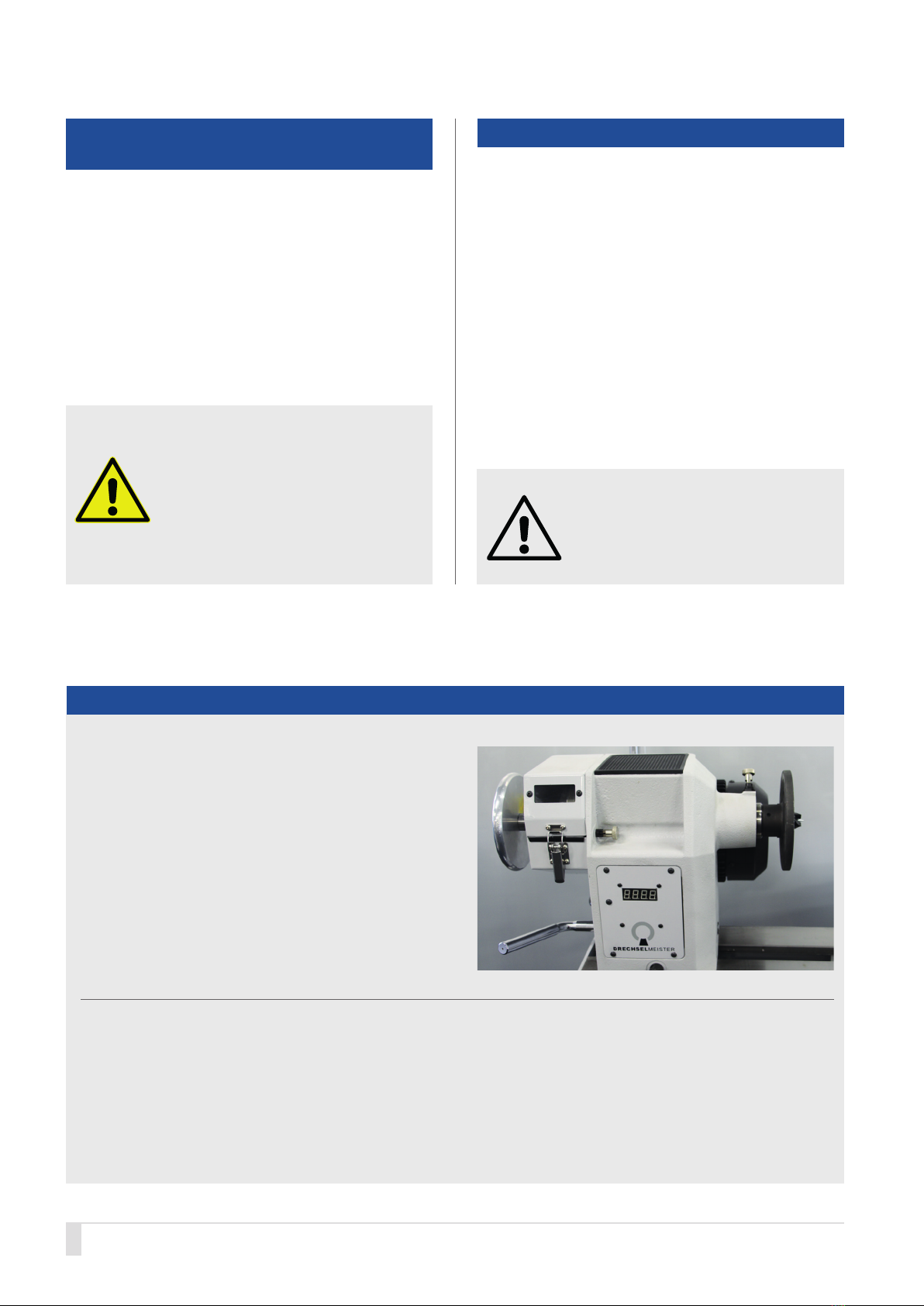
In order to turn on the power unit, first turn the main switch
clockwise until it clicks into place. On the movable control
box, switch on the motor and increase the speed on the po-
tentiometer. (Figures see next page)
Automatic deactivation
Stratos is equipped with a zero-voltage switch which deac-
tivates the lathe in the event of a power outage or when the
pulley cover is lifted, and it prevents restarting when the po-
wer has been restored. The speed can also be turned off via
the frequency converter in the event of overload during wood
turning. In order to restore the wood turning lathe to operation
in any case, the cause must be eliminated. In the event of a
power outage, power must be restored. If the cover has been
lifted, it must be closed again. In the event of overload, the
load must be reduced or the pulley with a lower speed must
be chosen.
Using the tool rest, the turning gouges are manually moved
toward the work piece. This poses a risk of injury because
the resulting cutting forces have to be countered by the user.
In order to compensate for the resulting forces, the turning
gouges must always rest firmly on the tool rest.
It is important that you read the operating instructions carefully
before initial use in order to familiarize yourself with the risks
that can be created by the operation of the machine (in parti-
cular rotating parts, resulting forces and risk of injury).
If you have no experience with wood turning, please get in-
formed before working with the wood turning lathe. In order
to do this, ask someone with experience in wood turning and
have them train you.
At our site, we are offering beginners‘ and advanced courses.
4. Description of functions
8© NEUREITER | Original Operating Manual Version 1.0
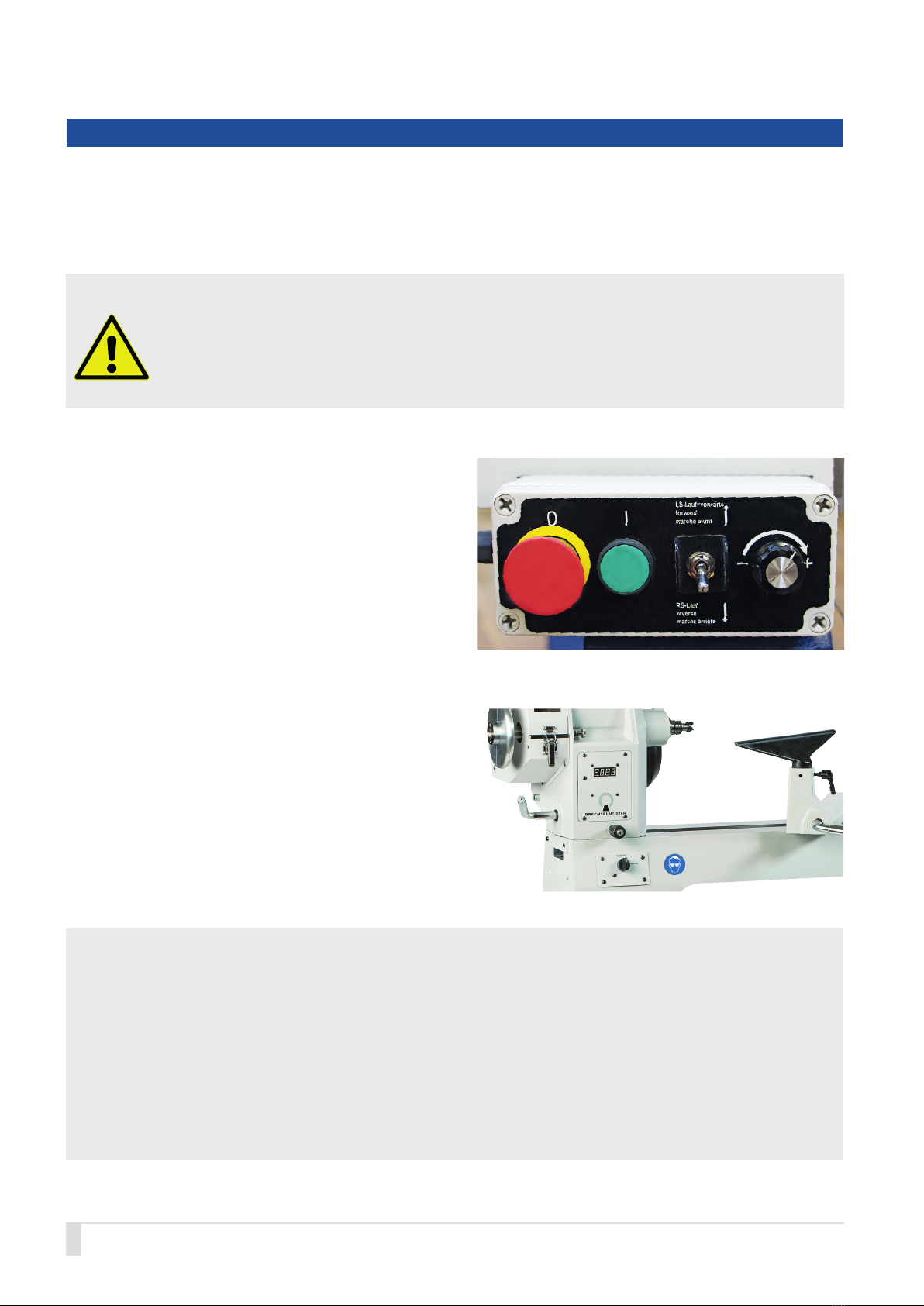
EMERGENCY STOP/OFF and ON Function
The lathe is equipped with a red combination switch (0) with
which it can be EMERGENCY STOPPED as well as stopped
in the conventional way. By pressing the red button (0), all
machine functions are deactivated.
To restart, press the green ON button (I).
The toggle switch is used to activate the machine‘s reverse
operation.
The potentiometer regulates the speed.
Warning signs on the wood turning lathe
The warning signs on the wood turning lathe are for your safe-
ty. Always keep them legible and observe their meaning.
5. Safety devices
The safety devices are for the protection of people and material property. Without intact safety devices, severe injuries can be the
consequence.
Danger!
The wood turning lathe must always be used with functioning safety devices. Turn off the lathe immediately on
noticing that a safety device is faulty or has been removed! All accessories added by the user must be equipped
with the specified safety devices.
Overview of other safety devices
The wood turning lathe is equipped with various safety devices:
1. Electrical grounding conductor which is connected to the local mains supply via the safety plug.
2. Cover with interrupter switch over the pulley drive.
3. Electric motor cover.
4. Emergency stop via the movable control unit.
5. Stop rods on both lathe ends.

9© NEUREITER | Original Operating Manual Version 1.0
6. Installation site requirements
Requirement Recommendation
Lathe installation site Position the Stratos 230 close to a power source (isolated socket). Ensure the floor is
level, solid and stable. Leave sufficient space around the machine. Also consider suffi-
cient space for when the headstock has been rotated, for the bed extension and/or the
outrigger. Other machines in the workshop must not interfere with the lathe‘s operation.
Lighting and ventilation Ensure adequate lighting (lighting intensity according to DIN 5035) and ventilation. Also
use adjustable lighting for your working area at the lathe so no shadow is cast on the
work piece. We recommend a light source with a value of at least 300 LUX, or even
better, 500 LUX at the cutting edge of the tool.
If possible, position the machine close to a window.
Electrical equipment To operate the wood turning lathe, a suitable, conventional 230 V isolated socket fused
with a 16 amp supply is required.
Electric cables and sockets must comply with local electricity regulations. If in doubt,
ask your electrical specialist. Avoid the use of an extension cable (see Chapter
„Connecting the wood turning lathe to the mains supply“).
Ventilation Adequately ventilate your work place. The degree of ventilation depends on the size of
the workshop and the number of work pieces being processed. The use of dust extrac-
tors and filters reduces health hazards.
Working height Set up the working height of the wood turning lathe so the spindle center is at the same
level as the user‘s elbow.
Working area When securing the lathe to the floor, free space around the lathe of at least 80 cm is
required for repairs and maintenance work.
Stand If the lathe is used without a stand, the operator must choose a suitable installation
surface. In this case, the outrigger cannot be used.
10 © NEUREITER | Original Operating Manual Version 1.0
7. Assembling the wood turning lathe
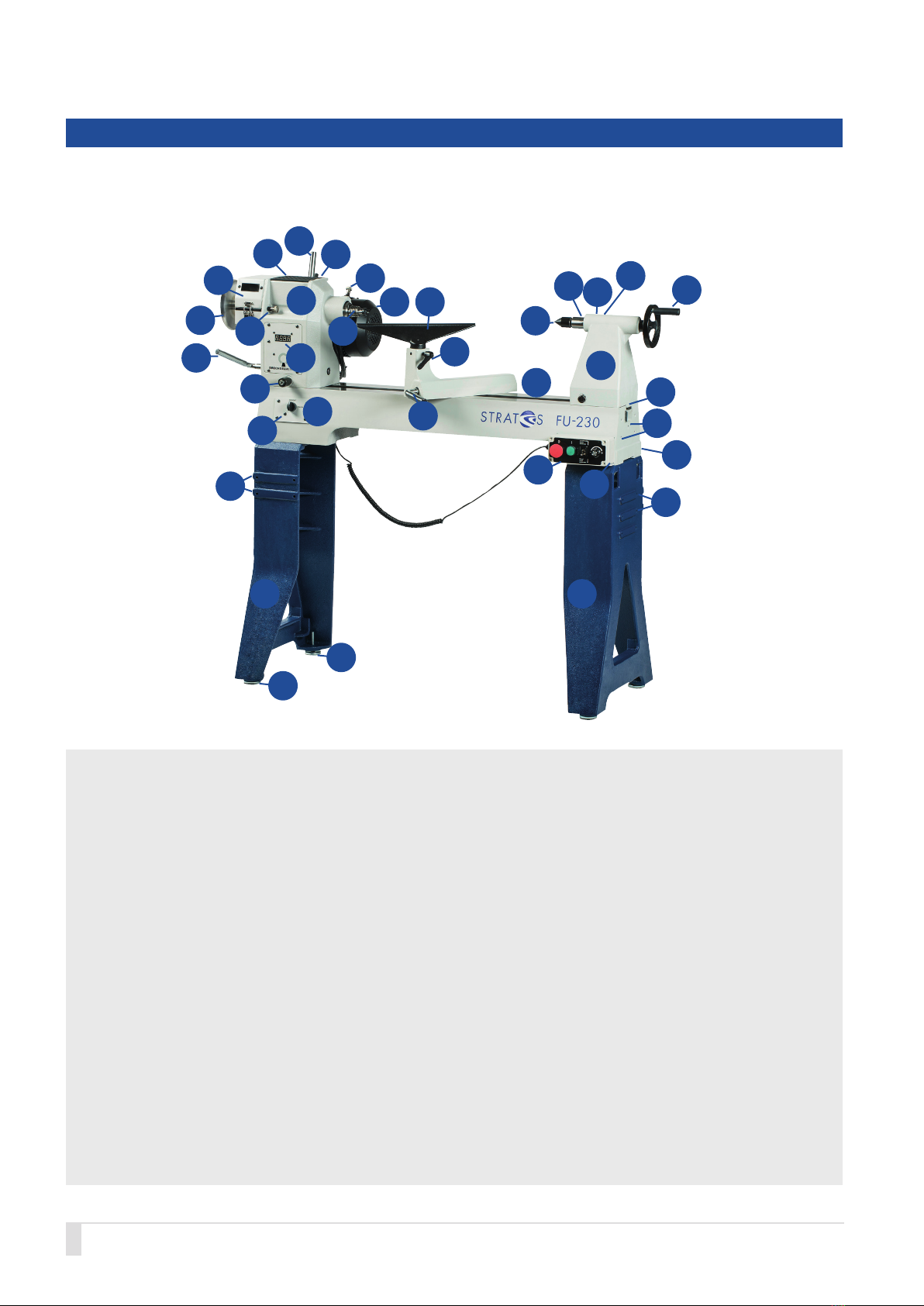
Description of the wood turning lathe
1 Headstock
1.1 Headstock pivot locking pin
1.2 Headstock clamping lever
1.3 Handwheel
1.4 Pulley cover
1.5 Rubber tray
1.6 Motor clamping lever
1.7 Quick-release lever for motor locking mechanism
1.8 Electric motor
1.9 Spindle locking pin
1.10 Spindle with M33 thread
1.11 Digital speed display
1.12 24-position locking pin
2 Lathe bed
2.1 Main switch
2.2 Movable control unit holder
2.3 Tool holder (rear)
2.4 Holes for outrigger bed extension
2.5 Movable control unit
2.6 Stop rod
3 Tailstock
3.1 Live center
3.2 Quill
3.3 Quill fine adjustment (on the rear)
3.4 Quick-release lever for quill locking
mechanism (on the rear)
3.5 Handwheel
4 Tool rest support
4.1 Tool rest
4.2 Quick-release lever
4.3 Tool rest support clamping lever
5 Stand
5.1 Level adjusting feet
5.2 Anchor points for bed extension
5.2
5.1
5.1
2.1
1.1
1.2
1.3
1.4
1.12
1.5 1.6
1.7
1.8 4.1
1.9
1.10
1.11
3.2 3.3
3.4
3.5
2.6
2.3
2.4
3
3.1
4
4.2
1
24.3
2.5
2.2
55
5.2

11© NEUREITER | Original Operating Manual Version 1.0
Warning!
• Be aware of the weight of the individual components
and handle them carefully to avoid causing yourself
any injuries.
• Ensure that all bolted joints are tight but not over-tigh-
tened. Check all bolted joints for tightness after eight
operating hours.
• During assembly, put the headstock down in such
a way that the cable connections are not damaged
and the cables are not disconnected under any cir-
cumstances.
• The cast iron stand was developed for use with the Stra-
tos 230. Using it with other machines can lead to injury.
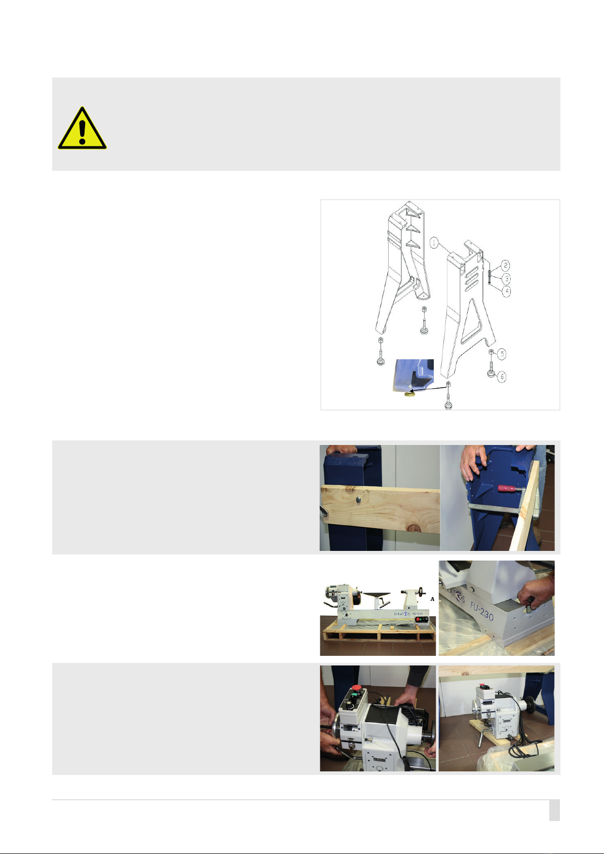
Assembly information:
We carefully packaged the machine at our site. Upon receipt, please check the packaging for damage or whether the machine has
become damaged during transport as well as whether the contents are complete. In the event of complaints, please report them
to your supplier immediately and do not start using the machine. Claims at a later stage will not be accepted. Using this machine
with others can lead to loss of warranty.
The packaging is made of raw material and can be returned to the raw materials cycle via the available local collection sites. Dispose
of the packaging material only when the wood turning lathe has been assembled and is functioning properly.
Carefully read the operating manual beforehand!
Tool and resource recommendations for assembly:
• To support the headstock, two timber bearers are needed.
• 14 mm wrench, Phillips screwdriver, Allen key for loosening the face plate from the spindle and the mounting parts.
• Commercially available spirit level.
• Timber board (length x width) 1,150 x 100 mm and about 20 mm thickness with two holes of Ø 9 mm according to the drilling
template (see Appendix 4) to secure the stand during assembly.
• A second person is essential during assembly.
Delivery contents:
Lathe bed, headstock, tailstock and tool rest support with tool rest are one unit. The stand and the accessories are packaged
in separate boxes.
Fig.: Delivery contents Fig.: Accessories
B Stand
B Stand
Accessories

12 © NEUREITER | Original Operating Manual Version 1.0
Delivery contents
ALathe bed with headstock, tailstock, tool rest support with tool rest 350 mm (1“ stems).
BStand.
CLive center with integrated ring and center point live center, MT2
DSpur center 25 mm, MT2.
EKnock out bar.
FFeet, height adjustable, 8 x 3/8“ x 50 mm.
GBolts 8 x 3/8“ for fixing the lathe bed to the stands.
HMorse taper double-sided, MT2, for aligning the centers.
IAllen keys 3 and 4 mm.
JFace plate wrench to loosen the face plate from the spindle.
KFace plate 150 mm with M33 x 3.5 mm thread with 2 set screws 5 mm.
LTool holder for the rear of the lathe bed.
MControl unit holder for the front of the lathe bed.
NIn the accessory set, there is a stainless steel handle which has to be attached to the top of the motor flange. It is used to
loosen the Poly-V belt.
GC D I
H
N
B F K
ML
E
J
F
13© NEUREITER | Original Operating Manual Version 1.0
Danger!
• During machine assembly, always make sure that your fingers do not get trapped in between the parts. Risk of
crushing!
• Be aware of the weight of the individual components and handle them carefully to avoid causing yourself any
injuries.
Preparing to attach the stands to the lathe bed.
The two stands can be used on the left and the right.
Place them flat on the floor and attach the feet to the threa-
ded holes on the bottom. Secure them with suitable hex
nuts. To ensure that the wood turning lathe is positioned
securely and horizontally, you can alter the level adjusting
feet nuts at any time. To level the lathe, use a commercially
available spirit level.
The feet can be omitted if the floor is level and even and the
working height is sufficient.
The feet are used to compensate for unevenness and to
adjust the working height by up to 50 mm (rule of thumb for
lathe height: elbow at spindle height).
Attach the prepared timber board (use the drilling template
Appendix 4) to the fixing points on the left stand for the
outrigger using the supplied 3/8“ bolts. Then align the stand
in such a way that it is flush with the board, and secure the
board on the right stand using a bar clamp.
Before fixing the lathe bed to the stand, reduce the weight
of the lathe bed. Remove the plastic cover, headstock,
tailstock and tool rest support. To do this, loosen the stops
on both ends of the lathe bed and watch out for the connec-
ted cables.
Using two people, lift the headstock from the lathe bed
guide and place it on two timber bearers next to the lathe
between the stands.
Advice: Lock the spindle in place and insert a 12 mm bar
into the hollow spindle for easier transport.

14 © NEUREITER | Original Operating Manual Version 1.0
Make sure that cables do not get damaged.
Using two people, lift the empty lathe bed onto the stand
and align it.
Now fix the lathe bed to the stand with the remaining two
bolts. First, hand-tighten the bolts so you can adjust the
lathe bed and the feet after removing the bar clamp. After
tightening the two bolts on the lathe bed, you can remove
the timber board and tightly connect the lathe bed using the
supplied bolts.
Using the spirit level, check that the lathe bed is level. If
required, adjust the lathe using the feet.
Using two people, carefully lift the headstock into the lathe
bed guide.
First, place the tool rest support on the lathe bed, then the
tailstock.
Now replace the stops (stop rod and stop plate) at the ends
of the lathe bed.

15© NEUREITER | Original Operating Manual Version 1.0
Warning!
You must repeat the process of aligning the headstock whenever you have rotated it, such as when using the
outrigger.
Now insert the stainless steel handle (N) into the specified
socket on the motor flange to tighten the drive belt.
Attach the holder for the movable control unit to the front
right of the lathe bed.
The tool holder is attached to the opposite rear of the lathe
bed.
Both parts are secured from the outside to the lathe bed
with two Allen set screws each.
Aligning the headstock.
Loosen the headstock and rotate it so it is aligned with the
lathe bed and the tailstock. Mount the double ended Morse
taper (H) in the tailstock and, using the tailstock, insert it into
the spindle so that it slides in without resistance.
If required, align the headstock accordingly. When quill and
spindle are aligned, lock the headstock in position using the
clamping lever.
Alignment
H

16 © NEUREITER | Original Operating Manual Version 1.0
Assembling the bed extension (available as an option)
Art. DDSTR-BV400N
The bed extension can be used to extend the lathe bed
and for the outrigger. This accessory is not part of the
shipment.
1. Before attaching the bed extension, push the tailstock
away from the end of the lathe bed.
2. Using a second person, position the bed extension
flush with the lathe bed and insert the Allen set screws
with the washers through the holes in the bed extensi-
on into the threaded holes on the lathe bed.
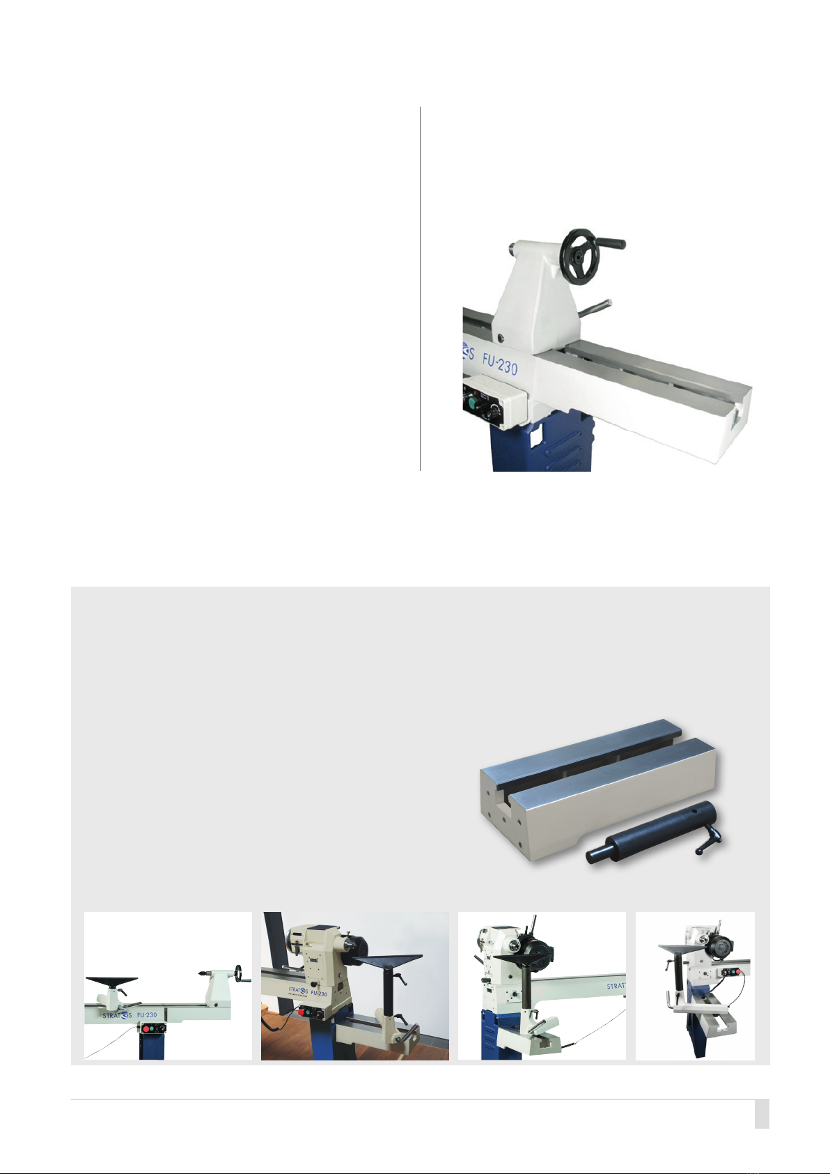
Easy quick-release system (available as an option)
Art. DDSTR-AS
This high quality equipment enables rapid replacement of
the lathe bed extension and the outrigger. This accessory
is not part of the shipment.
The wood turning lathe has been assembled.
Outrigger
fixing points
17© NEUREITER | Original Operating Manual Version 1.0
3. Lift the lathe bed extension slightly above the top edge
of the lathe bed. Tighten the screws only so much that
the extension is held in position.
IMPORTANT: So the tailstock can easily be moved
along the groove, the lathe bed and extension have to
be accurately aligned.
Advice: Before tightening the lathe bed, guide the
tailstock over the connection point and tighten it. This
will align the connection.
4. If required, use a rubber hammer or a hammer with
a wooden block underneath in order to align the bed
extension with the lathe bed.
Never directly hit the metal surface with a metal
hammer!
Tap until both surfaces and the insides are completely
aligned.
5. Then tighten the Allen set screws. Ensure that the alig-
nment of both parts does not change.
6. To prevent the tailstock accidentally falling out, remove
the stop rod from the lathe bed and replace it at the
end of the bed extension.
Outrigger (available as an option)
If the bed extension is used as an outrigger, fix it to the specified points on the side of the lathe bed or on the left side of the
lathe. Insert the supplied shaft extension into the tool rest support.
Combined bed extension/outrigger (available as an option)
Art. DDSTR-BV400N
Made of 400 mm cast iron extension and shaft extension for
tool rest. Can be used on three fixing points! Can be used for
Stratos and Twister.
18 © NEUREITER | Original Operating Manual Version 1.0
7. Connecting the wood turning lathe
to the mains supply
The operator must use an isolated socket fused with 16 amp.
The mains voltage and rating must correspond to the data on
the lathe‘s rating plate.
The building must be equipped with mains protection which is
connected to the lathe‘s safety plug.
The supplied safety plug must be used with a suitable isolated
socket which has been appropriately installed, according to
country-specific electrical regulations.
Danger!
• A lathe which has been connected and
does not comply with regulations can lead
to an electric shock.
• All connections and repairs to the electri-
cal equipment must be carried out by a
qualified electrician.
8. Commissioning
To begin with, check that the machine has been set up and
assembled correctly. Before commissioning, remove all loose
parts and tools that may be lying on the lathe.
Turn the main switch to „0“. On the movable control unit, turn
the toggle switch to „forward“ and turn the potentiometer all
the way to the left, to zero.
Insert the safety plug into the designated isolated socket.
Now switch the main switch to „I“. (Switch it back to „0“ when
you have finished working with the lathe.) To start the machi-
ne, press the green button (I) on the movable control unit. By
turning the potentiometer, you are increasing the speed to the
required rpm.
9. Using the wood turning lathe
Headstock
The headstock consists of the power unit (electric motor)
with quick-release lever and clamping lever to loosen the
belt, pulleys with gear ratio, spindle with M33 x 3.5 mm
thread and additional 34 mm flange as well as a No. 2 Mor-
se taper (MT2), knob for spindle lock (clicks into place at 90°
rotation), knob for 24-position indexing (clicks into place at
90° rotation), cover for pulleys with viewing window, clam-
ping lever for cover, handwheel, clamping lever for moving
the headstock, digital display of the spindle speed in rpm,
and headstock pivot locking pin.
When starting the lathe with a work piece
inserted, ensure the potentiometer is on
„0“. Then press the green ON button to turn
on the speed.
Replacing the spur center
Using the supplied knock out bar, the spur center can be
pushed out from the rear through the spindle shaft. Initially,
try to push out the spur center with gentle taps. During this
process, carefully hold on to the outside of the spur center
with your other hand. Do not hold on to the spur center at
its face or by the jaws as this can cause injuries.
Replacing the live centers
The center punch can be ejected by turning the headstock
handwheel counter-clockwiese. Alternatively, it can also be
pushed out from the rear with the knock out bar.

19© NEUREITER | Original Operating Manual Version 1.0
Tailstock
Never loosen the quill on the tailstock or the tailstock itself
while the work piece is rotating. The tailstock is equip-
ped with a MT2 quill. The quill guide is equipped with
a quick-release lever which must always be fixed using
the handwheel after securing the side grain. Next to the
quick-release lever, there is a lock lever which is used for
adjusting the quill. Please ask your specialist dealer if nee-
ded.
On the back of the tailstock, there is the clamping lever
for fixing the tailstock on the lathe bed. It can be removed
by loosening the snap ring and relocated to the front of
the tailstock.
Regularly check proper clamping of the tailstock on the
lathe bed. The tailstock guarantees an exact alignment
between center punch and spur center. This guarantees
low vibration woodturning and is the best prerequisite for
exact drilling with a tailstock.
In order to move the tailstock on the lathe bed, loosen the
clamping lever, move the tailstock to the required position
and secure it there again.
To move the quill in or out, loosen the quill‘s quick-release
lever and turn the handwheel. Live centers and tools with a
No. 2 Morse taper (MT2) can be used with the quill. In order
to attach the tool, insert it quickly and tightly by hand into
the quill support. Do not hit it into the socket.
In order to prevent the tool falling out, hold on to it from the
outside. Caution: The center point can cause injuries.
Tool rest
After loosening the clamping lever, the tool rest support is
moved to the required position on the lathe bed and secu-
red there.
Move the tool rest close to the work piece. Every wood tur-
ner will choose the best setting for himself/herself. Before
turning on the lathe, the work piece is rotated manually to
ensure that it has no contact with the tool rest. During the
work process, the lathe is stopped and the tool rest is ad-
justed at regular intervals.
Locking device (excenter cleat)
If the headstock, tailstock or tool rest support cannot be
secured on the lathe bed, the excenter cleat must be read-
justed. Pull the headstock, tailstock or tool rest support to
the end of the lathe bed and loosely tighten the self-locking
nut (see image).
Danger!
• As long as wood turning tools are in con-
tact with the work piece, they have to rest
securely on the tool rest.
• In order to prevent trapping your fingers during sanding
or polishing work, the tool rest must be removed from the
work piece.

20 © NEUREITER | Original Operating Manual Version 1.0
Spindle lock
The spindle lock can be activated by a 90° turn. The spindle
has a total of 9 location holes for locking. Activate the spind-
le lock in order to loosen the chuck etc. from the spindle.
Movable control unit and main switch
Position the main switch to ZERO (0) to turn the machine off
and to ON (I) to turn it on.
The main switch should be used only at the beginning and
the end of the wood turning work. General turning on and
off takes place via the movable control unit.
Position the movable control unit in an easy-to-reach place
or on the designated holder.
• The red button (0) is a combination button for
EMERGENCY STOP and OFF (0) during woodturning.
• The green ON button (I) is used to turn on the lathe
during woodturning.
• The toggle switch is for forward and reverse operation.
It is usually in the forward position. Reverse operation
is rarely used, e.g. during repeated sanding.
• The potentiometer (poti) is used to regulate the speed.
Turn it clockwise and the speed increases. Turn it
counter-clockwise and the speed decreases.
24-position indexing
By turning the knob (1) by 90°, the 24-position indexing
clicks into position. This enables an even graduation in 15°
increments during one turn of the spindle. Using this gradu-
ation, the spindle can be divided 24, 12, 8, 6, 4 and 2 times
per rotation.
Warning!
Always position the movable control unit wi-
thin reach on the lathe or in the designated
holder so you can activate the EMERGEN-
CY STOP button (0) at any time.
When working with chucks, face plates and
other M33 tools, a stop rod must be used
during reverse operation.
It is essential that the motor is not turned on
during locking of the spindle.
You must make sure that the mains plug has
been disconnected. Do not turn the motor on
during locking.
Use the 24-position indexing only for graduation, not for loo-
sening a chuck from the spindle.
1
Other manuals for FU-230
1
Table of contents
Other STRATOS Lathe manuals

Popular Lathe manuals by other brands

King Industrial
King Industrial KWL-1016C instruction manual

King Industrial
King Industrial KWL-1643ABC instruction manual

Smithy
Smithy MI-1440L Operator's manual

Rikon Power Tools
Rikon Power Tools 70-100 owner's manual

King Canada
King Canada KC-0712ML instruction manual

Grizzly
Grizzly G0782 owner's manual


