Optimum D240 Vario User manual

OPTIMUM
MASCHINEN - GERMANY
30 / 11 / 2007 Page 1Add-on kit D240/D280 ; Version 1.3.3
© 2007
GB
Rebuilding instruction
Version 1.3.3
Add-on kit CNC lathe
D240/D280
Keep for future reference!

OPTIMUM
MASCHINEN - GERMANY
30 / 11 / 2007Page 2 Add-on kit D240/D280 ; Version 1.3.3
© 2007 GB
Inhaltsverzeichnis
1 Packing list D240/ D280; D240 Vario/ D280 Vario
2 Packing list CNC special rebuilding kit, Z-axis D240/D280
3 Safety warnings (warning notes)
3.1 Classification of hazards......................................................................................................... 7
3.1.1 Glossary of symbols .................................................................................................... 7
3.2 Proper use .............................................................................................................................. 8
3.3 Required auxiliary material...................................................................................................... 8
4 Assembly
4.1 Assembly X-axis...................................................................................................................... 9
4.2 Assembly Z axis.................................................................................................................... 24
5 Wiring of step motors on the machine
5.1 Assembly X- / Z-axis............................................................................................................. 33
5.2 Wiring X- / Y- / Z-axis............................................................................................................ 33
6 Mounting examples reference switch D240 and D280
7 Appendix
7.1 Copyright............................................................................................................................... 38
7.2 Terminology/Glossary........................................................................................................... 38
7.3 Warranty................................................................................................................................ 39
7.4 Disposal ................................................................................................................................ 39
7.5 Product follow-up .................................................................................................................. 40

OPTIMUM
MASCHINEN - GERMANY
Packing list D240/ D280; D240 Vario/ D280 Vario
30 / 11 / 2007 Page 3Packing list D240/ D280; D240 Vario/ D280 Vario Add-on kit D240/D280 ; Version 1.3.3
© 2007
GB
1 Packing list D240/ D280; D240 Vario/ D280 Vario
Maschinemodell
Machine type CNC - D240/ D280
Artikelnummer Komplettpaket
Item No complete package 357 0240
Netto Gewicht
Net Weight 5,5 kg
Brutto Gewicht
Gross Weight 6 kg
Abmessung (Lx B x H)
Dimensions (L x W x H) 280 x 220 x 145 mm
Nr.
No Bezeichnung
Description Artikelnummer
Item No Teile Nr.
Part No Grösse
Size Abbildung
Illustration
Stck.
Qty.
1
Zahnriemenscheibe für Spindel Z-Achse
Toothed belt disk for shaft Z axis 359 0221 D 240
CNC-01
40 Zähne,
HTD-40-3M-15
(40 teeth) 1
Zahnriemenscheibe für Spindel Z-Achse
Toothed belt disk for shaft Z axis 359 02214 D 280
CNC-01
40 Zähne,
HTD-40-3M-15
(40 teeth) 1
2Zahnriemenscheibe für Motor Z-Achse
Toothed belt disk for motor Z axis 359 0223 CNC-03 26 Zähne,
HTD-26-3M-15F
(26 teeth) 1
3Gehäuse für Z-Achse
Housing for Z axis 359 0225 CNC-06 1
4Schrittmotor für Z-Achse
Step motor Z axis 357 3307 CNC-11
34H280-01A
4,2 NM
6 A
40 V
1
5Abdeckplatte Antrieb Z-Achse
Cover plate drive Z axis 0 357 0240 08 CNC-08 1
6Zahnriemen für Z-Achse
Gear belt for Z axis 3590210 CNC-09 3M-15
225 Zähne
(225 teeths) 1

Packing list D240/ D280; D240 Vario/ D280 Vario
OPTIMUM
MASCHINEN - GERMANY
30 / 11 / 2007Page 4 Packing list D240/ D280; D240 Vario/ D280 Vario Add-on kit D240/D280 ; Version 1.3.3
© 2007 GB
7Wellendichtring
Rotary shaft seal 0 357 0240 10 24x40x7 1
8Zahnriemenscheibe für Spindel X-Achse
Toothed belt disk for shaft X axis 359 0208 CNC-04 18 Zähne,
HTD-18-3M-9F
(18 teeth) 1
9Gehäuse für X-Achse
Housing for X axis 359 0224 CNC-05 1
10 Abdeckplatte Antrieb X-Achse
Cover plate drive X axis 0 357 0240 07 CNC-07 1
11 Spindelverlängerung 1 X-Achse
Spindle extension 1, X-axis 359 0222 CNC-02 1
12 Lager für X-Achse
Bearing for x axis 0 357 0240 11 626-2RS 1
13 Zahnriemenscheibe für Motor X-Achse
Toothed belt disk for motor X axis 359 0208 BF 20
CNC-08
18 Zähne,
HTD-18-3M-9
(18 teeth) 1
14 Zahnriemen für X-Achse
Gear belt for X axis 359 0228 CNC-10 3M-9
210 Zähne
(210 teeth) 1
15 Schrittmotor für X-Achse
Step motor X axis 357 3304 CNC-12
23H280-01EA
2,2 NM
3 A
40 V
1
16 Spindelverlängerung 2 X-Achse
Spindle extension 2, X-axis 0 357 0210 13 CNC-13 1
Nr.
No Bezeichnung
Description Artikelnummer
Item No Teile Nr.
Part No Grösse
Size Abbildung
Illustration
Stck.
Qty.

OPTIMUM
MASCHINEN - GERMANY
Packing list D240/ D280; D240 Vario/ D280 Vario
30 / 11 / 2007 Page 5Packing list D240/ D280; D240 Vario/ D280 Vario Add-on kit D240/D280 ; Version 1.3.3
© 2007
GB
17 Schraube
Screw GB/T 79 M3 x 5 1
18 Schraube
Screw GB/T 70 M3 x 6 2
19 Schraube
Screw GB/T 79 M4 x 5 1
20 Schraube
Screw GB/T 70 M5 x 12 4
21 Schraube
Screw GB/T 70 M5 x 20 4
22 Schraube
Screw GB/T 70 M6 x 15 4
23 Sechskantmutter
Hex. Nut M8 x 1 1
24 Kabel geschirmt
Cable wire protected 359 0212 4-conductor x
0,75mm27m
Nr.
No Bezeichnung
Description Artikelnummer
Item No Teile Nr.
Part No Grösse
Size Abbildung
Illustration
Stck.
Qty.
Prüfer:
Verified by: Datum:
Date:

Packing list CNC special rebuilding kit, Z-axis D240/D280
OPTIMUM
MASCHINEN - GERMANY
30 / 11 / 2007Page 6 Packing list CNC special rebuilding kit, Z-axis D240/D280 Anbausatz D240/D280 ; Version 1.3.3
© 2007 GB
2 Packing list CNC special rebuilding kit, Z-axis D240/D280
Maschinemodell
Machine type CNC - D 240/D280
Artikelnummer Komplettpaket
Item No complete package 357 0241
Netto Gewicht
Net Weight 0,3 kg
Brutto Gewicht
Gross Weight 0,5 kg
Abmessung (Lx B x H)
Dimensions (L x W x H) 140 x 90 x 80 mm
Nr.
No Bezeichnung
Description Artikelnummer
Item No Teile Nr.
Part No Grösse
Size Abbildung
Illustration
Stck.
Qty.
1Zahnriemenscheibe für Spindel Z-Achse
Toothed belt disk for shaft Z-Axis 035702411 CNC-14 40 Zähne,
HTD-40-3M-15
(40 teeth) 1
2Spindelverlängerung für Z-Achse
Spindel extension, Z-Axis 035702412 CNC-15 1
3Mutter
Nut DIN EN
28675 M8 x 1 1
Prüfer:
Verified by: Datum:
Date:

OPTIMUM
MASCHINEN - GERMANY
Safety warnings (warning notes)
30 / 11 / 2007 Page 7Safety warnings (warning notes) Add-on kit D240/D280 ; Version 1.3.3
© 2007
GB
3 Safety warnings (warning notes)
3.1 Classification of hazards
We classify the safety warnings into various levels. The table below gives an overview of the
classification of symbols (pictograms) and warnings for the specific danger and its (possible)
consequences.
3.1.1 Glossary of symbols
Pictogram Alarm expres-
sion Definition/Consequences
DANGER! Imminent danger that will cause serious injury or death to
personnel.
WARNING! Risk: A danger that might cause serious injury or death to
personnel.
CAUTION! Danger or unsafe procedure that might cause injury to
personnel or damage to property.
ATTENTION!
Situation that could cause damage to the machine and
product and other types of damage.
No risk of injury to personnel.
INFORMATION
Application tips and other important or useful information
and notes.
No dangerous or harmful consequences for personnel or
objects.
In the case of specific dangers, we replace the pictogram by
or
General dan-
ger with a warning
of injuries to
hands, hazardous
electrical volt-
age,
rotating parts.
gives additional indications
£calls on you to act
enumerations

Safety warnings (warning notes)
OPTIMUM
MASCHINEN - GERMANY
30 / 11 / 2007Page 8 Safety warnings (warning notes) Add-on kit D240/D280 ; Version 1.3.3
© 2007 GB
3.2 Proper use
WARNING!
In the event of improper use of the add-on pieces
• will endanger personnel,
• will endanger the machine and other material property of the operator,
• may affect proper operation of the machine.
The add-on pieces as conversion kit are provided for the computer-aided - CNC, Computerised
Numerical Control - milling operations of your machine.
The drive of the step motors may also be performed manually with a control unit (potentiome-
ter).
Improper
use! The milling machine with the adapter kit must only be placed and operated in dry and ventilated
rooms.
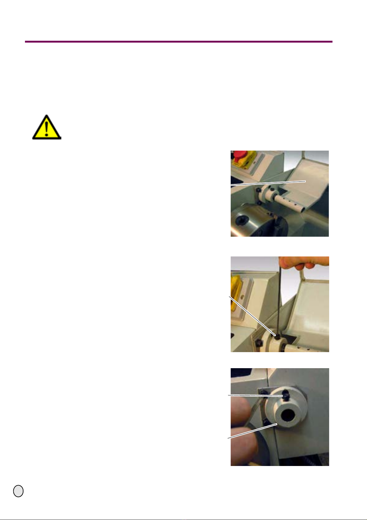
The handwheels need to be disassembled.
If the adapter kit is used in any way other than described above, modified without the authorisa-
tion of Optimum Maschinen Germany GmbH or operated with different process data, then it is
being used improperly.
We do not take any liability for damages caused by improper use.
We would like to stress that any modifications to the construction, or technical or technological
modifications that have not been authorised by Optimum Maschinen Germany GmbH will also
render the guarantee null and void.
3.3 Required auxiliary material
• Means of shaft lock-down device "Loctite 601, join the shaft"
• The designation of parts in the assembly description corresponds to the numbering of the
packing list.
• In order to degrease the shaft, a cleaner for brakes or a corresponding cleaning agent is
required.
• A tenacious grease e.g. Mobilux 2 or a corresponding lubrication grease serves to grease the
bearings.
• Lubricating oil for threading.
• Required tools: reamers 6 H7; twist drill 5mm, 5,8mm and 6,5mm;
• Countersink; plastic tip hammer; prick punch and scriber;
• A set of Allan keys; fork wrench; screw driver;
• Tongs and stripping tongs; cutter; screw tap M6;
• Manual drilling machine; shifting square; box wrench 13mm; chipping spanner
• Soldering iron; small chisel ; abrasive cloth; metal cutting saw

OPTIMUM
MASCHINEN - GERMANY
Assembly
30 / 11 / 2007 Page 9Assembly Add-on kit D240/D280 ; Version 1.3.3
© 2007
GB
4 Assembly
CNC conversion kit MK D 24 PD / MK D 28 PD
4.1 Assembly X-axis
WARNING!
Before starting the work disconnect the machine from electrical power supply, only plug
it in upon expressive order if the rebuilding measures have not been terminated.
£Open the chuck protection of the
lathe chuck.
Illustr.: 4-1: Lathe chuck protection
£Unscrew the safety screw of the
lathe chuck protection.
Illustr.: 4-2: Unscrew lathe chuck protection
£Draw the lathe chuck protection off
the fixture.
Illustr.: 4-3: Fixture lathe chuck protection
Lathe chuck protec-
tion
Safety screw
Safety screw
Fixture lathe chuck
protection

Assembly
OPTIMUM
MASCHINEN - GERMANY
30 / 11 / 2007Page 10 Assembly Add-on kit D240/D280 ; Version 1.3.3
© 2007 GB
£Unscrew the 3 fastening screws of
the splashboard on the headstock.
Illustr.: 4-4: Fixture headstock
£Unscrew the 2 fastening screws of
the splashboard of the engine bed.
£Remove the splashboard of the
lathe in order to easily excess all
parts of the lathe.
Illustr.: 4-5: Fixture engine bed
CAUTION!
Danger by crushing.
The slide is very heavy!
£Crank the compound slide with the
handwheel to the back.
£Draw the compound slide backward
out of the guiding device.
Illustr.: 4-6: Remove compound slide
Upper fastening
screws
Lower fastening
screws
Engine bed
Fastening screws
Compound slide

OPTIMUM
MASCHINEN - GERMANY
Assembly
30 / 11 / 2007 Page 11Assembly Add-on kit D240/D280 ; Version 1.3.3
© 2007
GB
£Measure the distance from the edge
of the spindle to the edge of the
lathe slide.
£The measured distance of +42mm is
the total length of the shaft exten-
sion (part 11).
Illustr.: 4-7: Measure spindle distance
£Measure the calculated length from the thread of the shaft elongation and cut the part into
lengths with the saw. Please also cut off the corresponding sleeve with the same length as
you have cut off the elongation and glue it onto the elongation with the shaft retention agent.
£Unscrew the fastening screw of the
handwheel on the compound slide.
Illustr.: 4-8: Remove the screw of the handwheel
£Remove the handwheel of the com-
pound slide to the back off the spin-
dle.
Illustr.: 4-9: Remove handwheel
Edge spindle
Edge lathe slide
Handwheel com-
pound slide
Unscrew the screw of
the handwheel
Pull off the hand-
wheel

Assembly
OPTIMUM
MASCHINEN - GERMANY
30 / 11 / 2007Page 12 Assembly Add-on kit D240/D280 ; Version 1.3.3
© 2007 GB
£Pull off the feather key from the
spindle with tongs.
Illustr.: 4-10: Remove the feather key
£Pull off the first bearing of the spin-
dle completely.
Illustr.: 4-11: 1st bearing of the spindle
£Unscrew the 3 fastening screws of
the graduated collar.
£Pull off the graduated collar from the
spindle.
Illustr.: 4-12: Pillow block X axis
Tongs
Feather keys
Spindle compound
slide
1st bearing
Fastening screw
Graduated collar of
the X axis

OPTIMUM
MASCHINEN - GERMANY
Assembly
30 / 11 / 2007 Page 13Assembly Add-on kit D240/D280 ; Version 1.3.3
© 2007
GB
£Pull off the 2nd bearing of the spin-
dle to the back.
Illustr.: 4-13: 2nd bearing of the spindle
£Remove the spindle of the X axis
(compound slide) from the pillow
block.
£If the spindle clamps, just turn it a lit-
tle when pulling it off.
Illustr.: 4-14: Spindle X axis
£Remount the fixture of the lathe
chuck protection on the machine.
Illustr.: 4-15: Fixture lathe chuck protection
Spindle X axis
Bearing of the spindle
Pillow block
Spindle X axis
Fixture of lathe chuck
protection
Fastening screws

Assembly
OPTIMUM
MASCHINEN - GERMANY
30 / 11 / 2007Page 14 Assembly Add-on kit D240/D280 ; Version 1.3.3
© 2007 GB
£Assemble the lathe chuck protec-
tion.
Illustr.: 4-16: Lathe chuck protection
£Tense the spindle of the X-axis with
the thread onto the lathe chuck. Do
not tense it too firm as otherwise the
thread might be damaged.
CAUTION!
Make sure that the shaft is running
true, as otherwise the shaft exten-
sion might be out of true which
might cause malfunctions.
Illustr.: 4-17: Spindle in lathe chuck
CAUTION!
For the following works the machine may be connected to the power supply.
Lathe chuck protec-
tion
Lathe chuck
Lathe chuck
Spindle X-axis

OPTIMUM
MASCHINEN - GERMANY
Assembly
30 / 11 / 2007 Page 15Assembly Add-on kit D240/D280 ; Version 1.3.3
© 2007
GB
£Drill about 15 mm deep into the
spindle with a 5.8 mm drill.
£Deburr the hole with countersink.
£Remove the dirt from the hole with
compressed air.
Illustr.: 4-18: Hole in the spindle
£Ream the hole in the spindle with a
reamer 6 H7. Use oil as lubricant.
£When reaming, make sure that the
reamer is being held at right angles.
£Remove the chips from the reamed
hole with compressed air.
Illustr.: 4-19: Reaming of 6H7
£Check if the longer relief of the shaft
elongation (part 11) fits into the
reamed hole 6 H7.
Illustr.: 4-20: Check shaft relief
CAUTION!
Disconnect the machine in order that there is zero potential.
Lathe chuck
Drill 5,8 mm
Reamer 6 H7
Spindle X axis
Shaft elongation

Assembly
OPTIMUM
MASCHINEN - GERMANY
30 / 11 / 2007Page 16 Assembly Add-on kit D240/D280 ; Version 1.3.3
© 2007 GB
£Remove the lathe chuck protection
from the lathe again.
Illustr.: 4-21: Disassemble lathe chuck protection
£Apply shaft retention agent onto the
longer relief of the shaft elongation
(part 11).
Illustr.: 4-22: Shaft retention agent
£Insert the shaft elongation (part 11)
into the reamed hole 6 H7 of the
spindle.
CAUTION!
Only reassemble the spindle when
the gluing agent has dried out.
Illustr.: 4-23: Elongate the shaft
Fixture lathe chuck
protection
Fastening screws
Shaft retention agent
Spindle X axis
Shaft elongation

OPTIMUM
MASCHINEN - GERMANY
Assembly
30 / 11 / 2007 Page 17Assembly Add-on kit D240/D280 ; Version 1.3.3
© 2007
GB
£Push the spindle with the glued spin-
dle elongation into guiding device
again.
Illustr.: 4-24: Push the spindle into the guiding device
£Completely push the second bear-
ing on the spindle.
CAUTION!
The bearing needs to be lubricated
again with lubricant for bearings.
Make sure that the bearing is com-
pletely free from dirt.
Illustr.: 4-25: 2nd bearing of the spindle
£Fasten the 3 fastening screws of the
graduated collar.
Illustr.: 4-26: Graduated collar
Spindle X axis
Guiding device of the
spindle
Spindle X axis
2nd bearing of the
spindle
Fastening screws
Graduated collar

Assembly
OPTIMUM
MASCHINEN - GERMANY
30 / 11 / 2007Page 18 Assembly Add-on kit D240/D280 ; Version 1.3.3
© 2007 GB
£Completely push the 1st bearing of
the spindle again.
CAUTION!
The bearing needs to be lubricated
again with lubricant for bearings.
Make sure that the bearing is com-
pletely free from dirt.
Illustr.: 4-27: 1st bearing of the spindle
£Insert the feather key into the spin-
dle again - if required - slightly drive
it in with a hammer.
Illustr.: 4-28: Feather key in the spindle
£Mount the handwheel of the com-
pound slide onto the spindle.
£Tighten the handwheel on the spin-
dle with the fastening screws.
Illustr.: 4-29: Handwheel compound slide
Spindle X axis
1st bearing of the
spindle
Spindle X axis
Feather key
Handwheel com-
pound slide
Fastening screw

OPTIMUM
MASCHINEN - GERMANY
Assembly
30 / 11 / 2007 Page 19Assembly Add-on kit D240/D280 ; Version 1.3.3
© 2007
GB
CAUTION!
Danger by crushing. The compound slide is very heavy!
£Re-insert the compound slide from
the back into the guiding.
£Make sure that the guiding is free
from dirt.
£Crank the slide with the handwheel
into its normal position.
Illustr.: 4-30: Mount compound slide
£Push the ball bearing (part 12) into
the housing (part 9).
£Remove the crest which eventually
had been formed due to the opera-
tion with an abrasive cloth.
Illustr.: 4-31: Bearing in the housing
£Plug the housing (part 9) from the
backside onto the shaft extension
(part 11).
£Aline at a rectangle to the engine
bed.
£Mark out the holes for the fixture of
the housing with a pen.
Illustr.: 4-32: Apply housing
Compound slide
Guides
Ball bearing
Housing for X axis
Angle
Housing for X axis

Assembly
OPTIMUM
MASCHINEN - GERMANY
30 / 11 / 2007Page 20 Assembly Add-on kit D240/D280 ; Version 1.3.3
© 2007 GB
£Center the marked out holes with a
center punch.
Illustr.: 4-33: Mark the holes with the center punch
£Drill with the 5mm drill, a hole of a
depth of 10mm into the lathe slide.
£After drilling the hole needs to be
countersinked with a countersink in
order that the thread can be cut.
£Blow out the holes with air in order
to remove the drill chips.
Illustr.: 4-34: Drilling for M6
£Cut the thread into the lathe slide
with an M6 screw tap. Use oil for
threading.
£When threading check the correct
cut of the thread with a 90° angle.
£Cut thread M6 into the lathe slide.
Illustr.: 4-35: Lathe slide
Lathe slide
Center punch
Drill 5mm
Spindle extension
Lathe slide
90° angle
Screw tap M6
This manual suits for next models
2
Table of contents
Other Optimum Lathe manuals

Optimum
Optimum OPTI turn TU 3008G User manual

Optimum
Optimum OPTIturn TX 6222 User manual

Optimum
Optimum OPTIturn TM 3310 User manual

Optimum
Optimum OPTiturn TM 4010 User manual

Optimum
Optimum OPTIturn TU 2506VB User manual

Optimum
Optimum OPTIturn TU 3008 User manual

Optimum
Optimum Optiturn TU 2506 User manual

Optimum
Optimum OptiTurn TH 6620D User manual

Optimum
Optimum OptiTurn TH 6620D User manual