Rikon Power Tools 70-100 User manual

Mini Lathe
Model: 70-100
Owner’s Manual
For more information:
For Parts or Questions:
Record the serial number and date of purchase
in your manual for future reference.
Serial number:
Date of purchase:
Part # 70-100M2

Safety Warning
IMPORTANT! Safety is the single most important consideration in the operation of this equipment. The following
instructions must be followed at all times.
There are certain applications for which this tool was designed. We strongly recommend that this tool not be modified
and/or used for any other application other than that for which it was designed. If you have any questions about its
application, do not use the tool until you have contacted us and we have advised you.
General Safety Warnings
KNOW YOUR POWER TOOL. Read the owner’s manual carefully. Learn the tool’s applications, work
capabilities, and its specific potential hazards.
ALWAYS KEEP VISITORS AWAY FROM RUNNING MACHINES.
All visitors should be kept a safe distance from the work area.
ALWAYS MAKE THE WORKSHOP CHILDPROOF.
Childproof with padlocks, master switches, or by removing starter keys.
NEVER OPERATE A TOOL WHILE UNDER THE INFLUENCE OF DRUGS,
MEDICATION, OR ALCOHOL.
ALWAYS WEAR PROPER APPAREL.
Never wear loose clothing or jewelry that might get caught in moving parts. Rubber-soled footwear is
recommended for the best footing.
ALWAYS USE SAFETY GLASSES AND WEAR HEARING PROTECTION.
Also use a face or dust mask if the cutting operation is dusty.
NEVER OVERREACH.
Keep your proper footing and balance at all times.
ALWAYS GROUND ALL TOOLS.
If your tool is equipped with a three-pronged plug, you must plug it into a three-hole electric
receptacle. If you use an adapter to accommodate a two-pronged receptacle, you must attach the
adapter plug to a known ground. Never remove the third prong of the plug.
ALWAYS AVOID DANGEROUS ENVIRONMENTS.
Never use power tools in damp or wet locations. Keep your work area well lighted and clear of clutter.
ALWAYS REMOVE THE ADJUSTING KEYS AND WRENCHES FROM TOOLS AFTER USE.
Form the habit of checking to see that keys and adjusting wrenches are removed from the tool before
turning it on.
ALWAYS KEEP YOUR WORK AREA CLEAN. Cluttered areas and benches invite accidents.
NEVER STAND ON TOOLS.
Serious injury could occur if the tool is tipped or if the cutting tool is accidentally contacted.
2

ALWAYS CHECK FOR DAMAGED PARTS.
Before initial or continual use of the tool, a guard or other part that is damaged should be checked to
assure that it will operate properly and perform its intended function. Check for alignment of moving
parts, binding of moving parts, breakage of parts, mounting, and any other conditions that may affect
its operation. A guard or other damaged parts should immediately be properly repaired or replaced.
ALWAYS DISCONNECT TOOLS.
Disconnect tools before servicing and when changing accessories such as blades, bits, and cutters.
ALWAYS AVOID ACCIDENTAL STARTING.
Make sure switch is in “OFF” position before plugging in cord.
NEVER LEAVE TOOLS RUNNING UNATTENDED.
Special Safety Rules For Lathes
SAVE THESE INSTRUCTIONS.
Refer to them often.
3
1. Donotoperate thismachineuntilyouhave readall ofthe followinginstructions.
2. Donotattempt tooperatethis machine untilitis completelyassembled.
3. Donotturn ON thismachine if anypiecesare missing.
4. Ifyouare not familiarwith the operationof the machine,obtain assistance froma qualified person.
5. Itishighly recommendedthatthis machinebe firmlymountedtoaflat andsecure worksurface.
6. Alwayswearprotective eyewear priorto operating thismachine.
7. Donotoperate thismachineif youare undertheinfluence ofdrugsand/or alcohol.
8. Removealljewelry priortooperating thismachine.
9. Donotwear anygloveswhile operatingthismachine.
10.Alwaysmakesure the powerswitch is intheOFF position priortoplugging in themachine.
11.Always make surethepower switchisin theOFFposition when doingany assembly orsetup
operation.
12.Alwaysturnthe power switchtothe OFF positionandlet the workpiececome to acompletestop
priorto removal.
13.Useonly sharplathetools.
14.Theuse ofany accessoriesorattachments notrecommended maycauseinjurytoyou and
damageyour machine.
15.Thismachine mustbe properlygrounded.
16.Whenturningbetween centers,makesure headstockandtailstock aresnugagainst workpiece.
17.Whenfaceplate turning,rough-cutwork piececloseto thefinishedshape before screwingto face
plate.
18.Never jam tools into work piece or take too big a cut.
19.Donot operatethis machinewithout followingalltheseinstructions.
20.Keepthese instructionsfor futurereference.

70-100
12”
9-1/2”
16”
1/2HP,1Ph,115V only
6
430,810,1230,1810,2670,3900 RPM
1”x8
MT2
MT2
3/8”
2-1/2”
31-3/4”(L)x18”(W)x11-1/2”(H)
88.5 lbs
ModelNumber
SwingOverBed
SwingOver Tool RestBase
WorkingDistanceBetween Centers
Motor
Speeds
Speed Ranges
SpindleNose in xTPI
HeadstockTaper
TailstockTaper
HoleThroughSpindle
RamTravel
OverallDimensions
NetWeight
Table of Contents
SafetyWarnings.....................................................................................................................................................2
LatheSafetyRules...............................................................................................................................................3
Specifications.........................................................................................................................................................4
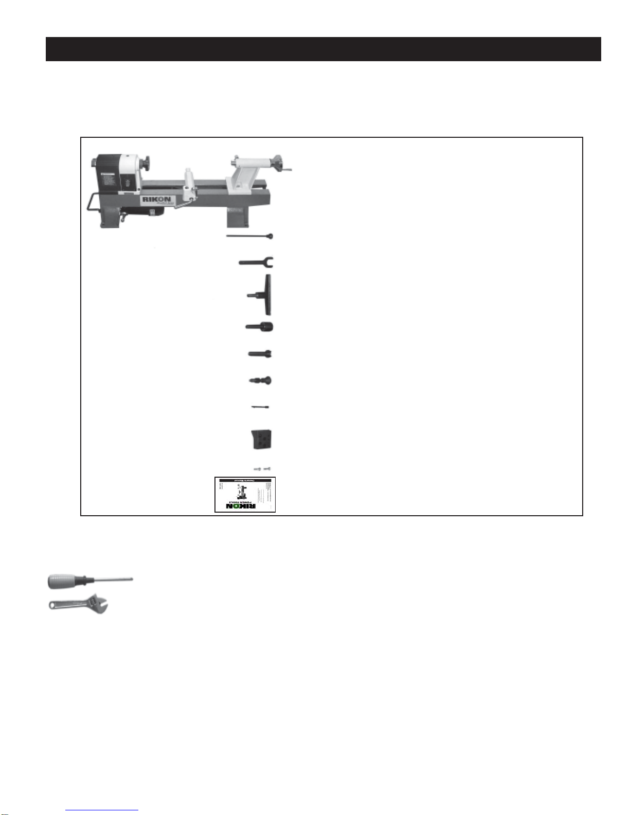
UnpackingandContents......................................................................................................................................5
GettingtoKnowYourLathe...................................................................................................................................6
Assembly................................................................................................................................................................6
InstallingtheToolRestandBase.........................................................................................................................6
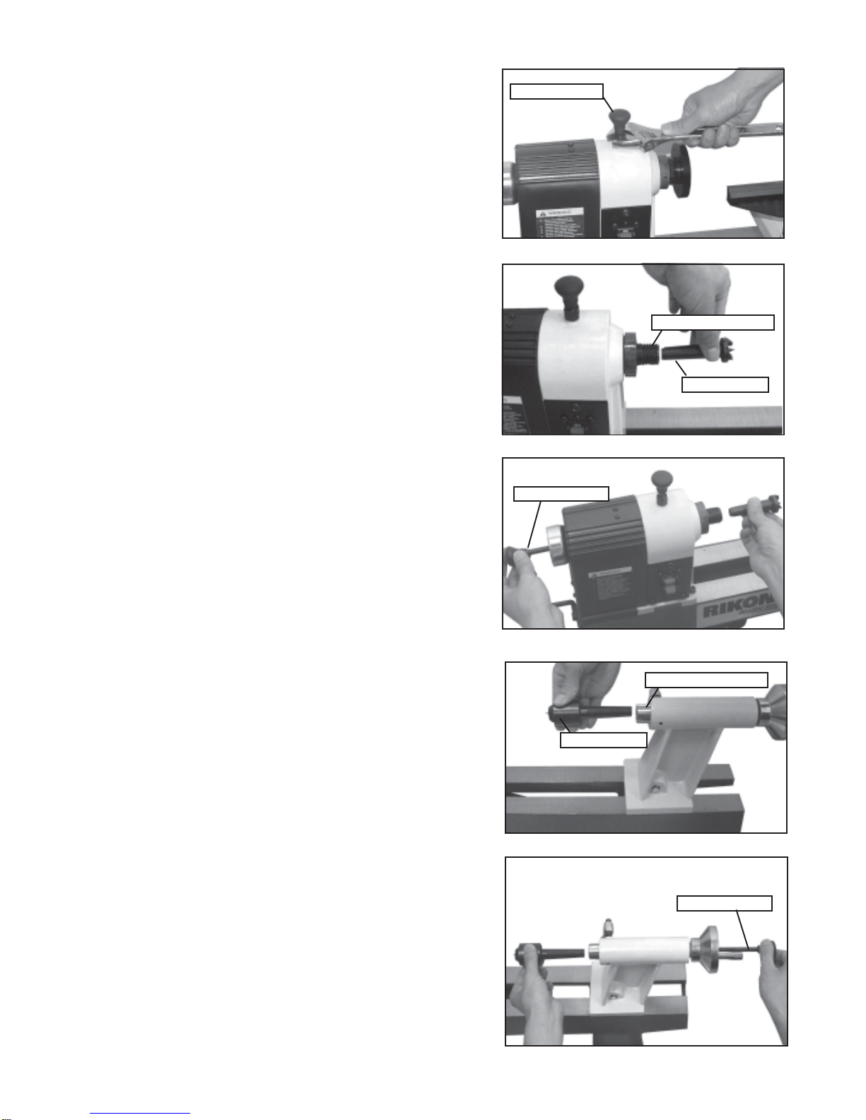
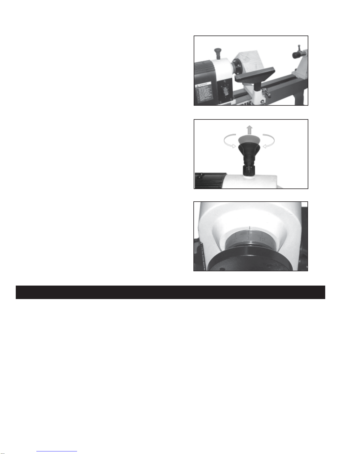
InstallingSpindleLock...........................................................................................................................................7
AttachingtheSpurCenter.....................................................................................................................................7
AttachingtheLiveCenter......................................................................................................................................7
InstallingtheFaceplate..........................................................................................................................................8
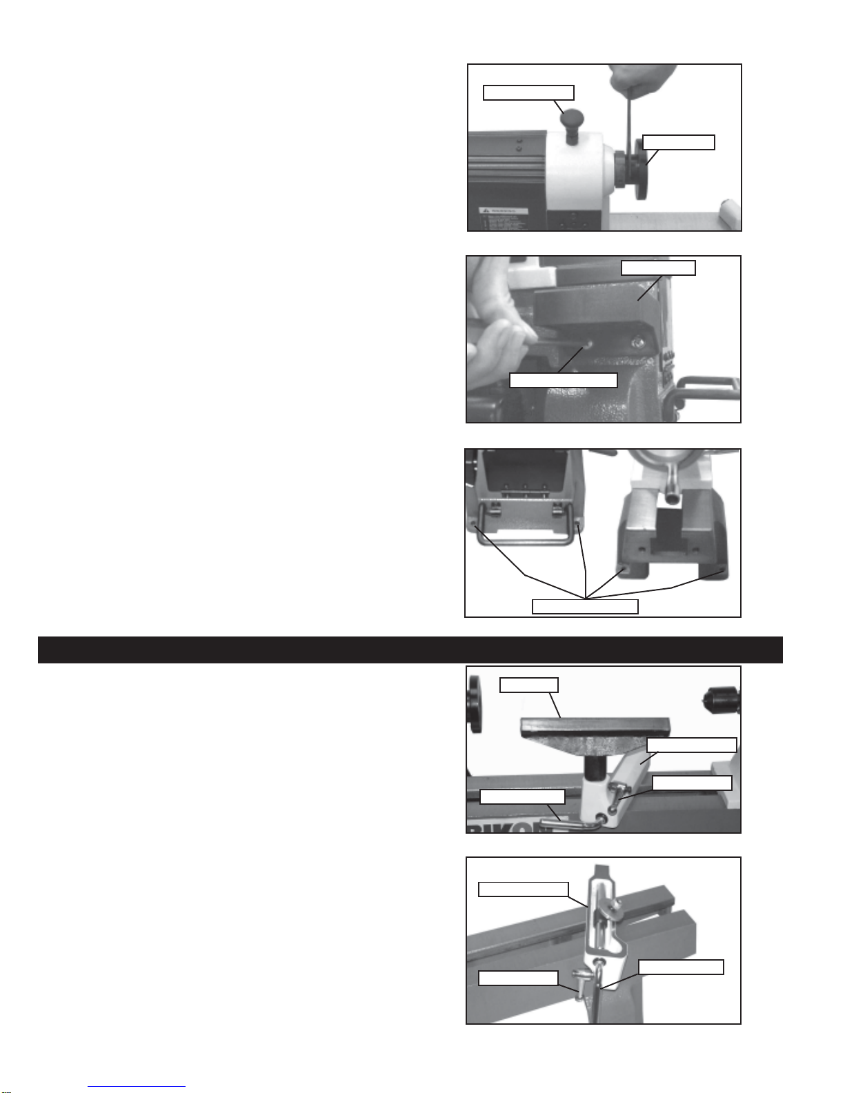
InstallingtheToolHolder........................................................................................................................................8
SecuringtheLathetoaWorkSurfaceorStand..................................................................................................8
Adjustments............................................................................................................................................................8
AdjustingtheToolRest..........................................................................................................................................8
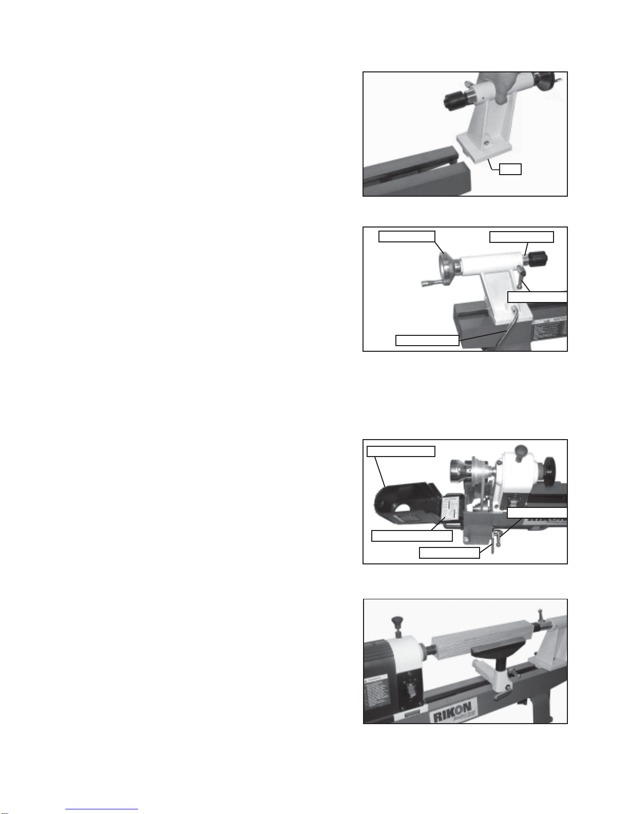
AdjustingtheTailstock...........................................................................................................................................9
ChangingSpindleSpeeds....................................................................................................................................9
TypicalOperations.................................................................................................................................................9
Indexing/SpindleLock........................................................................................................................................10
Maintenance.........................................................................................................................................................10
ElectricalRequirements...............................................................................................................................................11
WiringDiagram......................................................................................................................................12
Troubleshooting....................................................................................................................................................13
ExplosionDiagram..............................................................................................................................................14
PartsList...............................................................................................................................................................15
Warranty.................................................................................................................................................................16
Notes......................................................................................................................................................................17
Specifications
4

5
Unpacking and Clean-up
1. Carefullyfinish removingallcontents fromshipping cartons. Comparecontentsoftheshipping
cartons with the list of contents above. Place parts on a protected surface.
2. Reportanyshipping damage toyour localdistributor.
3. Clean all rustprotectedsurfaces with keroseneordiesel oil. Do not use; gasoline, paintthinner,
mineralspirits,etc. These maydamagepainted surfaces.
4. Set packing material and shipping cartons to the side. Do not discard until machine has been
set up and is running properly.
Tools Required for Assembly
Item Description
Phillips Screwdriver
Adjustable Wrench
Contents of Package
Unpackyour lathefromits cartonand checktosee thatyouhave allof the followingitems.Do notturn
yourmachine ONifany ofthese itemsaremissing.Youmay causeinjuryto yourselfor damagetoyour
machine.
Unpacking and Checking Contents
Item Description Q’ty
A Lathe.........................................................1
B KnokoutBar..............................................1
C Wrench.....................................................1
D ToolRest....................................................1
E LiveCenter................................................1
F SpurCenter...............................................1
G SpindleLockAssembly..............................1
H KnokoutBarforLiveCenterpointer..........1
I ToolHolder................................................1
J Panheadscrew.......................................2
K Manual/WarrantyCard................................1

Item Description
1 Liftinghandle
2 Switch
3 Handwheel
4 Face plate
5 Spurcenter
6 Toolrest
7 Livecenter
8 Tailstock
9 Tailstockhandwheel
6
8
9
15
16
12
1
2
3411
79
5
14 13
610
17
Item Description
10 Tailstock spindlelockingarm
11 Tool restbase
12 Spindle lock
13 Toolholder
14 Motor
15 Lathe bed
16 Tailstock lockinglever
17 Tool restseatlocking lever
Themachine must notbeplugged inandthe powerswitchmust beinthe OFFpositionuntil assemblyis
complete.
Installing Tool Rest and Base On
Lathe Bed
Removethe tailstockassemblyby releasingthe
lockinghandle andslidingthe assemblyoffthe end
ofthe lathebed.
Slidethetool rest base ontothelathe bed and
reinstallthe tailstockassembly.
Loosenlockingarm and inserttool rest intotool
restbase, adjustheightup ordownand tighten
locking arm. (See Fig.01)
Getting to Know Your Lathe
Assembly
Lockingarm
Tool rest
Tool rest base
Fig.01

7
Installing Spindle Lock
Locatethe spindle lockassembly fromthecarton,
andinstall itontothe headwith an adjustable
wrench. (SeeFig.02)
Warning: Disengage spindle lock beforeturning
themachineon.
Spindle lock
Attaching Spur Center On The
Headstock
Insertspur center,with aNo. 2MorseTaper shank,
intotheheadstock spindle.(See Fig.03)
Fig.03
Spurcenter
Headstockspindle
Knockout Bar
Theknockout bar isused toremovethe spurcenter
fromthe headstockspindle. Insertknockoutbar
intoholeat opposite sidefromspur center.
(See Fig.04)
Fig.04
Knockoutbar
Attaching Live Center On the Tailstock
Insertthe livecenter,withaNo. 2MorseTaper
shankintothe tailstock spindle.(SeeFig.05)
Livecenter
Tailstock spindle
Fig.06
Toremovelive centerfrom thetailstockspindle,
loosenlocking armandrotate thehand wheel
counterclockwise to retractspindleinto thebodyof
thetailstock. Thelivecenter willbe pushedoutof
thespindle.
(See Fig.06)
Knockoutbar
Fig.02
Fig.05

8 Fig.11
Secure Lathe to a Solid Work Surface
Thelathe must beattachedto asolidwork surface
orstand. Fourmountingholes areeasily
accessible at the base of the lathe. (See Fig.09)
Adjustments and Operations
Adjusting the Tool Rest
Thetoolrest basecanbe easily movedalongthe
lathebed. Loosenlockinglever counterclockwise,
slidetoolrest base tonewposition, and tighten
lockinglever clockwise.
Toadjustthe heightof thetoolrest, loosenlocking
arm,raise or lowertoolrest, tightenlockingarm.
(See Fig.10)
Note: Position the tool rest as close to the work
piece as possible. Itshould be 1/8” above the
centerlineof theworkpiece.
Toadjustclamping actionofthe tool restbase,
removebase andadjustnut clockwisetotighten
andcounterclockwise to loosen.(SeeFig.11)
Tool rest
Lockingarm
Lockinglever
Tool rest base
Lockingarm Locking lever
Tool rest base
Fig.09
Mounting holes
Installing Tool Holder On the Lathe
Bed
Locatedthe toolholderfrom thecarton, andinstall
itonto the lathebedwith twopanhead screws.
(See Fig.08)
Panhead screw
Installing The Faceplate to the
Headstock
Threadthe faceplate clockwiseon to the
headstockspindle. Next, engagethe spindle lock
andstop thespindlefrom turning,andtighten
faceplatewith supplied wrench.(SeeFig.07)
Fig.07
Faceplate
Spindle lock
Warning: Disengage spindle lock beforeturning
themachineon.
Fig.08
Fig.10
Toolholder

9
Adjusting Tailstock
Loosenlocking lever tomove the tailstockalong
thelathe bed todesired position.Tightenlever.
Toadjustclamping actionofthe tailstock,removeit
fromlathe bedandadjust nutclockwise totighten
andcounterclockwise to loosen.(SeeFig.12)
Toadjusttailstock arm inorout, loosen locking
armand turnhandwheel. Whenthe tailstockarm is
inadesiredposition, tighten locking arm.
(See Fig.13)
Thetailstock arm willtravel from0”to 2-1/2” Lockingarm
Lockinglever
Handwheel Tailstock arm
Nut
Changing Spindle Speeds
Thelathe features asix step motorand spindle
pulleysto provide differentspindle speeds. Open
accesscovertochange spindle speeds.
(See Fig.14)
Withaccesscover open,loosenlocking arm.
Raiselever toreleasetension onmotorpulley and
tightenlockingarm. Check speedandbelt position
chartinsideaccess cover todeterminespindle
speed required.
Movedrive belt todesired pulley combination.
Loosenlocking arm,lowerlever,andthe motorwill
provideproper tensiononthe drivebelt.Tighten
locking arm and close access cover. (See Fig.14)
Access cover
Belt position Chart
Lockingarm
Tension lever
Typical Operations
Thelathe is setup foratypical spindleturning
operation.(See Fig.15)
Fig.12
Fig.13
Fig.14
Fig.15

CAUTION! BEFORE CLEANING OR CARRYING OUT MAINTENANCE WORK, DISCONNECT
THE MACHINE FROM THE POWER SOURCE (WALL SOCKET). NEVER USE WATER OR
OTHER LIQUIDS TO CLEAN THE MACHINE. USE A BRUSH. REGULAR MAINTENANCE OF THE
MACHINE WILL PREVENT UNNECESSARY PROBLEMS.
Keepthelathe bedcastingclean and lubricated.
Keepthe outside ofthe machine cleanto ensure accurateoperation of allmoving parts andprevent
excessive wear.
Keepthe ventilationslotsof themotor cleantoprevent itfrom overheating.
Removeall sawdustand chipsfromthe latheafter eachuse.
10
Thelathe canbeset upfora faceplateturning
operation.The work pieceshould be “rough
cut” as close as possible to finished shape
beforemounting.(See Fig.16)
Indexing/Spindle Lock
Thedual purposeindexing/spindlelock is
positioned on the top of the headstock for ease of
use.The headstockindexing featurehas12equally
spaced positions. The spring loaded locking pin
assemblyis engagedbyturningtheknob ahalf turn
allowing it to drop into the desired position. To
disengage,lift thelockknobupand turna halfturn
either direction. (See Fig.17 & Fig.18)
The12 position indexingfeature allowsaccurate
patternwork onprojects suchasstraightfluting,
grooving,drilling, layout andmore.Thisfeature
alsoallows the usertolock thespindlefor
removingface plates,chucksandother
accessorieswithout needing twotools.
Tousethe spindle lock,disengagethe lockingpin
bylifting upand rotatingahalfturn.Thepinwill
engageinthe closestpinavailable. Once locked
anaccessorysuch as a face platecanberemoved
withthewrenchsupplied.
Fig.18
Maintenance
Fig.16
Fig.17

Inthe eventofa malfunctionorbreakdown, groundingprovides apathof leastresistancefor electric
currenttoreduce theriskof electric shock.Thistool isequippedwith an electriccord having an
equipment-groundingconductor anda groundingplug.Theplugmust beplugged intoa matchingoutlet
thatis properly installedand grounded inaccordancewith alllocalcodes andordinances.
Donot modifytheplug provided.Ifit willnot fittheoutlet, havetheproper outletinstalled byaqualified
electrician.
Improperconnection oftheequipment-grounding conductorcan resultin ariskof electricshock. The
conductor,with insulationhaving anouter surfacethat isgreenwithorwithoutyellowstripes, isthe
equipment-groundingconductor.If repair orreplacement oftheelectric cordorplug isnecessary, do not
connectthe equipment-groundingconductor toa liveterminal.
Checkwith a qualifiedelectrician orservicepersonnel ifthegrounding instructionsarenot completely
understood,or if indoubt astowhether thetoolis properlygrounded.
Useonly threewire extensioncordsthathavethree-pronggroundingplugs andthree-pole receptacles
thataccept thetool’splug.*
Repair or replace a damaged or worn cord immediately.
Thistool is intendedforuse onacircuit thathasan outletthatlooks theoneillustrated inFigureAbelow.
Thetool has agrounding plug thatlooks likethegrounding plugasillustrated inFigureAbelow.A
temporaryadapter, which lockslikethe adapterasillustrated in FigureBbelow, maybeused to connect
thisplugto atwo-polereceptacle, as showninFigure Bifa properly groundedoutletis notavailable.**
Thetemporary adaptershouldonly beused untilaproperlygroundedoutlet canbe installedbya
qualifiedelectrician.The green coloredrigidear ortab,extending from theadapter, must beconnected
toa permanentgroundsuchasa properlygrounded outletbox.
* Canadian electrical codes require extension cords to be certified SJT type or better.
** Use of an adapter in Canada is not acceptable.
Electrical Requirements
11

WARNING:Thismachine mustbe grounded.
Replacementof the powersupply cableshouldonly bedoneby aqualified electrician.
Wiring Diagram
12
Motor
Switch
Plug

Troubleshooting
13

Explosion Diagram
14

Parts List
15
KEY No. Description Part No. KEY No. Description Part No.
70-100
70-100
70-100
70-100
70-100
70-100
70-100
70-100
70-100
70-100
70-100
70-100
70-100
70-100
70-100
70-100
70-100
70-100
70-100
70-100
70-100
70-100
70-100
70-100
70-100
70-100
70-100
70-100
70-100
70-100
70-100
70-100
70-100
70-100
70-100
70-100
70-100
70-100
70-100
70-100
70-100
70-100
70-100
70-100
70-100
70-100
70-100
70-100
70-100
70-100
70-100
70-100
70-100
1
2
3
4
5
6
7
8
9
9A
10
11
12
13
14
15
16
17
18
19
19A
19B
21
22
23
24
24A
25
26
27
28
30
31
32
33
34
35
36
37
40
40A
40B
40C
40D
40E
41
42
44
45
46
47
48
50
Center point
Spur center
Faceplate
Spindle shaft
Bearing 6005-2Z
Ring retaining 47mm
Indexing gear
Hex socket set screw
M6x8
Spindle head
Warning label
Wave washer 47mm
Ring retaining 25mm
Poly-v-belt
Hex socket set screw
M6x12
Spindle pulley
Ring retaining 19mm
Handwheel
Spindle lock knob
Spindle lock tube
Spindle lock shaft
Spindle lock spring
Pin roll 3x16
Rounded insert
Power cable plate
Strain relief
Pan head screw
M5x12
Locking washer M5
Box switch
Switch plate
Lock switch
Pan head screw
M6x10
Pan head tapping screw
ST4.2x22
Pan head screw
M4x10
Locking washer M4
Hex. Nut M4
Close-end connector
Hex. Socket head screw
M6x35
Spring washer 6mm
Washer 6mm
Bed
Tool holder
Washer 6mm
Pan head screw
M6x16
Name label
Warning label
Cable tube
Fence
Pan head screw
M5x10
8" tool holder
Tool holder seat
Lock arm
Lock lever
Collar
1-JL93010001
1-JL93010002
1-JL93010003-001Y
1-JL93010004
1-BRG6005-2RSV2
1-CLP47GB893D1B
1-JL93010006
1-M6X8GB80B
1-JL93010007-050W
1-RK93081006
1-JL93010008
1-CLP25GB894D1B
1-JL93010009
1-M6X12GB80B
1-JL93010010
1-CLP19GB894D1B
1-JL93010011
1-0804011-01001S
1-JL93010013
1-JL93010015
1-JL93010014
1-PIN3X16GB879D1B
1-JL93010016
1-JL93040001
1-403106
1-M5X12GB818B
1-WSH5GB862D2B
1-JL93040002-001S
1-JL93040003
1-J-9301B
1-M6X10GB818B
1-ST4D2X25GB845B
1-M4X10GB818B
1-WSH4GB862D1B
1-M4GB6170Z
1-JL93040008
1-M6X35GB70B
1-WSH6GB93B
1-WSH6GB97D1Z
1-JL93010021-049W
1-JL93010017-001S
1-WSH6 GB97D1B
1-M6X16GB818B
1-RK93081002
1-RK93081005
1-JL93040004-001S
1-JL93010019-001Z
1-M5X10GB818B
1-JL93020001-001G
1-JL93020002-105L
1-JL930210000A
1-JL93020003
1-JL93020004
70-100
70-100
70-100
70-100
70-100
70-100
70-100
70-100
70-100
70-100
70-100
70-100
70-100
70-100
70-100
70-100
70-100
70-100
70-100
70-100
70-100
70-100
70-100
70-100
70-100
70-100
70-100
70-100
70-100
70-100
70-100
70-100
70-100
70-100
70-100
70-100
70-100
70-100
70-100
70-100
70-100
70-100
70-100
70-100
70-100
70-100
70-100
70-100
70-100
70-100
70-100
51
52
53
54
55
56
58
59
61
62
63
64
65
66
67
68
69
70
71
72
73
74
75
75A
76
77
78
79
80
81
82
83
84
85
90
91
92
93
94
95
97
98
99
100
101
102
103
104
104A
105
M2
Ring retaining 12mm
Clamp bolt cover
Position plate
Lock nut M10
Live center
Axle sleeve
Bolt
Ring retaining
Tail stock
Handwheel
Hex. Socket set screw
M6x12
Handwheel handle
Screw
Lock arm
Lock lever
Hex. Socket set screw
M5x8
Scr shaft
Spring
Clamp plate
Lock nut M10
Ring retaining 10mm
Lifting handle
Lifting handle clamping
Pan head screw
M5x10
Hinge
Lock washer M4
Pan head screw
M4x10
Motor pulley cover
Hex. Nut M4
Access cover
Warning label
Lock housing bracket
Lock housing
Belt position chart
Motor
Motor label
Belt tension handle
Belt tension handle cover
Locking arm
Special washer 8mm
Spring washer 6mm
Hex. Socket head screw
M6x15
Motor pulley
Hex. Socket set screw
M6x12
Brand label
RivetM2.5x5
Power cable
Knokout bar
Knokout bar
Wrench
Manual
1-CLP12GB894D1B
1-JL93020005
1-JL93030012
1-M10GB889Z
1-JL93031000
1-JL93030001
1-JL93030003
1-CLP12GB896B
1-JL93030005-050W
1-JL90030006
1-M6X12GB80B
1-JL93030007
1-JL93030009
1-JL93021000
1-JL93030009
1-M5X8GB77B
1-JL93030010
1-JL93030011
1-JL93030012
1-M10GB889Z
1-CLP10GB894D1B
1-JL93050001
1-JL93050002
1-M5X10GB818B
1-JL93050003
1-WSH4GB862D1B
1-M4X10GB818B
1-JL93050004-001Z
1-M4GB6170B
1-JL93050005-001S
1-RK93081004
1-JL93050006
1-JL93050007
1-RK93081003
1-H3612624
1-RK93081009
1-JL93041000
1-JL93040005
1-JL93021000B
1-JL93040007
1-WSH6GB93B
1-M6X15GB70B
1-JL93040006
1-M6X12GB78B
1-RK93081001
1-RVT2D5X5GB827C
1-U23182300-472
1-JL93070002
1-JL93070001
1-JL93070003
1-RK93082006

5-Year Limited Warranty
To take advantage of this warranty, please fill out the enclosed warranty card and send it to:
RIKON Warranty
16 Progress Rd.
Billerica, MA. 01821
The card must be entirely completed in order for it to be valid. If you have any questions
Warranty
16
RIKON Power Tools, Inc. (“Seller”) warrants to only the original retail consumer/purchaser of our
products that each product be free from defects in materials and workmanship for a period of five
(5) years from the date the product was purchased at retail. This warranty may not be transferred.
This warranty does not apply to defects due directly or indirectly to misuse, abuse, negligence,
accidents, repairs, alterations, lack of maintenance or normal wear and tear. Under no
circumstances will Seller be liable for incidental or consequential damages resulting from
defective products. All other warranties, expressed or implied, whether of merchantability,
. This warranty does not cover
products used for commercial, industrial or educational purposes.
This limited warranty does not apply to accessory items such as blades, drill bits, sanding discs or
belts and other related items.
Seller shall in no event be liable for death, injuries to persons or property, or for incidental,
contingent, special, or consequential damages arising from the use of our products.
To take advantage of this warranty proof of purchase documentation, which includes date of
purchase and an explanation of the complaint, must be provided.
The Seller reserves the right to effect at any time, without prior notice, those alterations to parts,
.

Notes:
17

For more information:
16 Progress Rd.
Billerica, MA. 01821
877-884-5167 / 978-528-5380
www.rikontools.com
Copyright RIKON Power Tools, Inc. 2006 Printed in China 5/06
Other manuals for 70-100
2
Table of contents
Other Rikon Power Tools Lathe manuals

Rikon Power Tools
Rikon Power Tools 70-105 User manual

Rikon Power Tools
Rikon Power Tools Woodfast 70-450 User manual

Rikon Power Tools
Rikon Power Tools 70-220VSR User manual

Rikon Power Tools
Rikon Power Tools 70-200EVS User manual

Rikon Power Tools
Rikon Power Tools 70-306 User manual

Rikon Power Tools
Rikon Power Tools 70-1824VSR User manual

Rikon Power Tools
Rikon Power Tools 70-1420VSR User manual

Rikon Power Tools
Rikon Power Tools 70-150VSR User manual

Rikon Power Tools
Rikon Power Tools 70-100 User manual

Rikon Power Tools
Rikon Power Tools 70-100 User manual