Streambox SBT3-9200 User manual

SBT3-9200 HD/SD Encoder/Decoder
Product Manual
SBT3-9300 HD/SD Encoder/Decoder
INSTALLATION MANUAL
REV. 0.93


CAUTION
TO REDUCE THE RISK OF ELECTRIC SHOCK
DO NOT REMOVE COVER (OR BACK)
NO USER-SERVICEABLE PARTS INSIDE
REFER SERVICING TO QUALIFIED SERVICE
PERSONNEL
Operation Notes
Do not remove cover for any reason unless authorized by a
Streambox support representative
Use only in a clean, temperature controlled environment
with ambient temperature between 15º and 26º Celsius
Do Not use in a humid or damp environment or expose the
unit to moisture
Do not power cycle the system excessively outside of
normal use
Verify all connections are secure before powering the
system
The product fans should be serviced after three years of
normal usage
The power supply should be checked every three years in
normal operation and replaced with a similar model if
needed
The motherboard has a battery which should be replaced
every 5 years in normal usage
Condensation Warning
Allow to warm up before using when moving from a cold to warm
environment
FAILURE TO ABIDE BY OPERATION GUIDELINES WILL VOID THE
PRODUCT WARRANTY
NOTE: THIS DEVICE COMPLIES WITH PART 15 OF THE FCC RULES.
OPERATION IS SUBJECT TO THE FOLLOWING TWO CONDITIONS:
1) THIS DEVICE MAY NOT CAUSE HARMFUL INTERFERENCE, AND
2) THIS DEVICE MUST ACCEPT ANY INTERFERENCE RECEIVED,
INCLUDING INTERFERENCE THAT MAY CAUSE UNDESIRED
OPERATIONS.


TABLE OF CONTENTS
1 INTRODUCTION..................................................... 1
1.1 SBT3-9200 HD/SD SERIES ENCODER/DECODERS ..............1
1.2 STREAMBOX®ACT-L3™ CODEC....................................1
1.3 SOLUTION FEATURES...................................................2
Streambox SBT3-9200 Front ......................................3
Streambox SBT3-9200 Rear .......................................3
2 SPECIFICATIONS..................................................... 4
3 UNPACKING AND INSTALLING ................................ 6
3.1 PACKAGE CONTENTS ...................................................6
3.2 RACK MOUNTING .......................................................6
Airflow .....................................................................6
4 MAKING CONNECTIONS .......................................... 7
4.1 NETWORK CONNECTIONS ..............................................7
4.2 UTILITY CONNECTIONS ................................................7
4.3 ENCODER CONNECTIONS ..............................................8
Video Input ..............................................................8
Audio Input ..............................................................9
4.4 DECODER CONNECTIONS ..............................................9
Video and Audio Output .............................................9
4.5 POWER CONNECTOR....................................................9
5 TURNING THE UNIT ON AND OFF .......................... 10
5.1 AUTO POWER ON..................................................... 10
5.2 POWER ON SEQUENCE ............................................... 10
5.3 POWER OFF............................................................ 10
Normal Power Off .................................................... 11
Forced Power Off..................................................... 11
6 CONFIGURING THE NETWORK SETTINGS .............. 12
6.1 IP CONFIGURATION -GRAPHICAL USER INTERFACE ............. 12
6.2 IP CONFIGURATION –FRONT PANEL CONTROL................... 13
Refreshing Network Settings “RECONNECT”................ 14
Viewing IP Configuration .......................................... 14
Setting a Static IP Address ....................................... 15

7 SETTING HD OR SD MODE ..................................... 18
7.1 ENCODER FRONT PANEL CONTROL (FPC)......................... 18
7.2 DECODER FRONT PANEL CONTROL (FPC)......................... 18
7.3 ENCODER GRAPHICAL USER INTERFACE ........................... 18
7.4 SET THE MODE BY EDITING THE SETTING FILE ................... 18
8 REMOTE ADMINISTRATION ................................... 21
8.1 WINDOWS REMOTE DESKTOP....................................... 21
9 ACCOUNTS AND PASSWORDS ................................ 22
9.1 GUI (WINDOWS)INTERFACE PASSWORD......................... 22
9.2 WEB INTERFACE ...................................................... 25
10 MAINTENANCE .................................................... 26
10.1 UPGRADING THE FIRMWARE ....................................... 26
Replacing the SSD Firmware drive............................. 26
APPENDIX A: FUNCTIONAL TEST ............................ 27
ETHERNET BENCH TEST ................................................... 27
Connect the Streambox Units ................................... 27
Enter IP Address Information.................................... 27
Set Test Parameters ................................................ 28
Test the System...................................................... 28


Streambox SBT3-9200 Installation Manual
1 Introduction
1
1 INTRODUCTION
This manual is written to provide installation and
configuration instructions for the SBT3-9200 HD/SD
Encoder/Decoder. For detailed information on configuration
of the ACT-L3 Transport included with the SBT3-9200 HD/SD
Encoder/Decoder please refer to the Streambox ACT-L3 HD
Transport Manual and Streambox ACT-L3 SD Transport
Manual.
1.1 SBT3-9200 HD/SD Series Encoder/Decoders
The SBT3-9200 HD/SD system provides superior
performance and reliability due to the unrivaled ACT-L3™
compression and networking features which include robust
forward error correction, burst error protection, and
bandwidth shaping technologies.
The system’s ability to encode, transmit, and playout either
live or file-based HD or SD video streams over digital
input/output formats sets the SBT3-9200 apart from other
HD solutions. In addition, Streambox’s integrated approach
to HD/SD video transport enhances the system's flexibility
and applicability to a variety of mission-critical operations.
The SBT3-9200 system works seamlessly with other
Streambox products including Streambox's solutions for
video management and playout. Benefits to users include:
faster video transmission over a variety of low data rate IP
networks, increased efficiency, and reduced cost of network
infrastructure.
1.2 Streambox® ACT-L3™ Codec
The innovative ACT-L3™ codec is an advanced video
compression technology optimized for interlaced and
progressive video and display systems. ACT-L3™ provides

1 Introduction
Streambox SBT3-9200 Installation Manual
2
higher HD and SD video quality at much lower data rates
than MPEG and H.264 compression. The ACT-L3™ codec is
adaptable to user selectable data rate requirements with
constant bit rate and variable bit rate modes.
The robust family of ACT-L3™ video transport solutions
features innovative error correction and bandwidth shaping
technologies which manage, control, and mitigate packet
loss and correct irregularities common to video delivery over
packet-based networks.
1.3 Solution Features
Reduced cost.
Live and file-based HD 1080i/720p/ 1080psf
Unrivaled HD video quality at data rates from 512
Kbps to 15 Mbps
Unrivaled SD video quality at data rates from 64 Kbps
to 15 Mbps
Support for digital HD/SD input and output formats
Mitigate packet loss, network jitter, and buffering
with robust forward error correction and other
advanced networking features
LDMP, “Low-Delay Multi-Path” network transport is
designed to guarantee fixed latency over multiple
network paths as well as aggregate all available
bandwidth for the use of streaming video, and
enhance reliability with constant network
measurement and receiver feedback. Adaptable to
user-defined data rate requirements
Superior performance and reliability over low cost,
low data rate IP networks
Low power requirement
Seamless local or remote system management via an
easy-to-use web interface
User configurable presets for quick and flexible setup
Streambox SBT3-9200 Installation Manual
1 Introduction
3
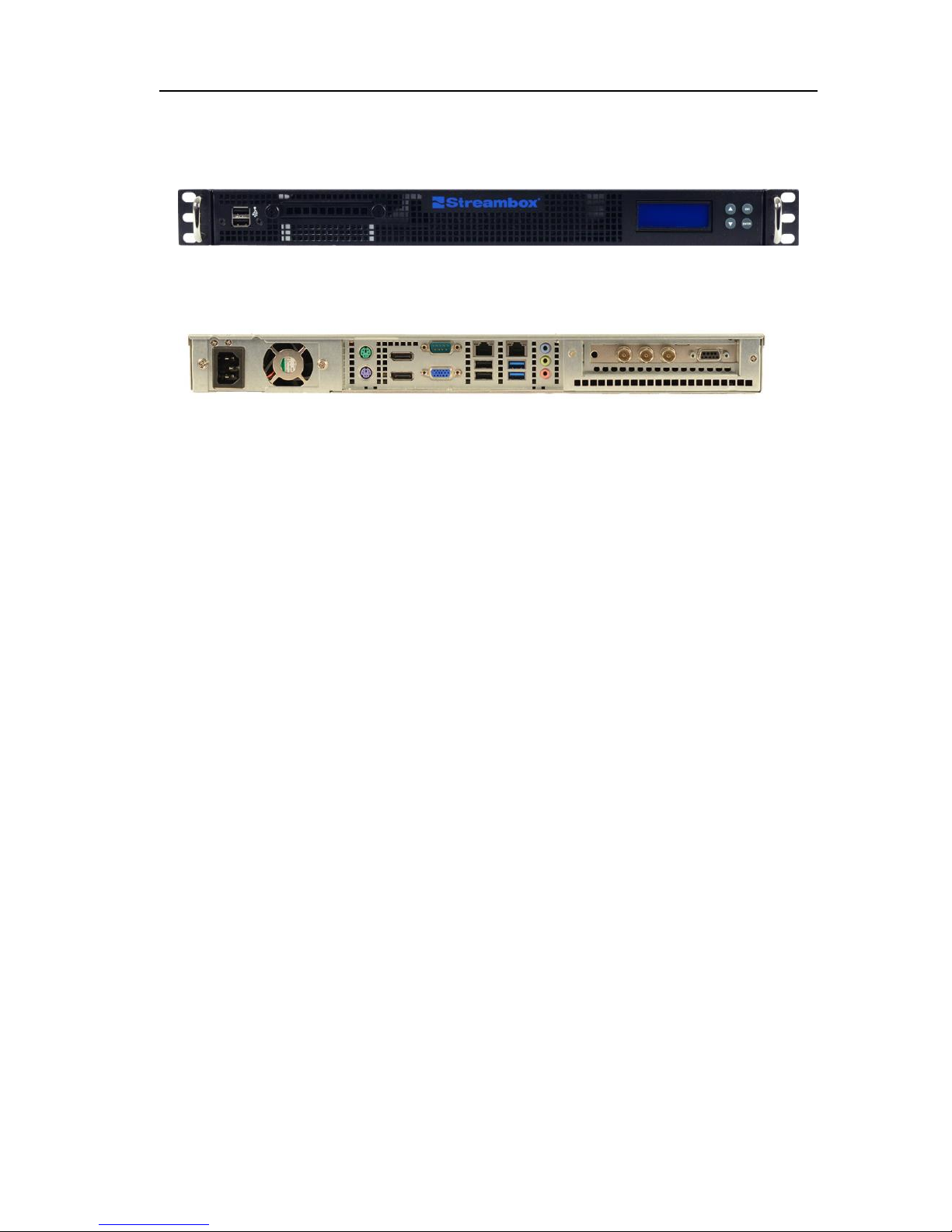
Streambox SBT3-9200 Front
Streambox SBT3-9200 Rear

2 Specifications
Streambox SBT3-9200 Installation Manual
4
2 SPECIFICATIONS
Connections
Video In
Type
Standard
SDI
BNC
HD-SDI SMPTE 292/296
1,2,4,6, 8 Channel embedded SDI audio, 24-bit SMPTE-259
Genlock
BNC
Analog color, HD-Tri-level (for decoding only)
Audio In
Type
Standard
SDI
Embedded AES
SDI
1,2,4,6,8 Channel embedded SDI audio, 24-bit SMPTE-259
IFB Analog
Audio
3.5mm
(1/8”)
1 channel analog input for IFB audio
Video Out
Type
Standard
SDI-Out
BNC
HD-SDI SMPTE 292/296
1,2,4,6,8 Channel embedded SDI audio, 24-bit SMPTE-259
Audio Out
Type
Standard
SDI Embedded
AES
SDI
available for SDI input, 1,2,4,6,8 Channel embedded SDI audio,
24-bit SMPTE-259
Network
Type
Standard
LAN 1
RJ-45
Ethernet 10/100/1000 Mbps
LAN 2
RJ-45
Ethernet 10/100/1000 Mbps
Utility
Type
Standard
VGA
D-SUB
VGA connection for graphical user interface
USB
Series A
USB 1.1/2.0
High Definition Transport
Parameter
Description
Video Encoding
Streambox ACT-L3™ Video codec
I/O resolution
and frame-rate
1080i/29.97,1080i/25 720p/59.94,720p/50 1080psf/23.94
Video encoding
resolution
1920x1080, 1440x1080, 1280x1080, 960x1080, 1280x720, 960x720, 800x720,
640x720
Video encoding
frame rate
Full,
Encoding color
space
4:2:0 or 4:2:2
Audio encoding
8-ch*, 6-ch*, 4-ch*, 2-ch, 1-ch. AAC, GSM or CELP 48 or 44.1 KHz

Streambox SBT3-9200 Installation Manual
2 Specifications
5
Video post-
filtering
Advanced interlaced/progressive post filtering, including de-blocking, de-
mosquito, and anti-aliasing
Bandwidth
Adjustable from 512kbps to 15Mbps
Encoding
latency
Adjustable from 200 to 8000 milliseconds
Network protocol
Multicast, Unicast UDP for IP, one-way
Broadcast and multiplex modes for dual-path
Forward Error
Correction
Adjustable, Off or On from 1% to 66% Reed-Solomon, Parity, Shuffle
*Available for HD SDI input only
Standard Definition Transport
Parameter
Description
Video Encoding
Streambox ACT-L3™ Video codec
I/O resolution and
frame-rate
480i/60,576i/50
Video encoding
resolution
NTSC: 720x480, 528x480, 480x480, 352x480, 352x240, 320x240
PAL: 720x576, 528x576, 480x576, 352x576, 352x288, 320x288
Video encoding frame
rate
Full,
Encoding color space
4:2:0 or 4:2:2
Audio encoding
2-ch, 1-ch. AAC, GSM or CELP 48 or 44.1 KHz
Video post-filtering
Advanced interlaced/progressive post filtering, including de-blocking, de-
mosquito, and anti-aliasing
Bandwidth
Adjustable from 64Kbps to 15Mbps
Encoding latency
Adjustable from 200 to 10000 milliseconds
Network protocol
Multicast, Unicast UDP for IP, one-way
Broadcast and multiplex modes for dual-path
Forward Error
Correction
Adjustable, Off or On from 1% to 66% Reed-Solomon, Parity, Shuffle
Hardware
Operating System
Windows Standard 7 x32 for Embedded Systems
Size
1U Rack Mountable
W18.9 x D20.67 x H1.77 [inch]
W480 x D525 x H45 [mm]
Weight
25lbs / 12Kg
Power requirements
100V –260V 50/60Hz
(Dual redundant hot-swappable PSU)
Power Consumption
180W (max) 1.6A at 115V (max)

3 Unpacking and Installing
Streambox SBT3-9200 Installation Manual
6
3 UNPACKING AND INSTALLING
When removing the unit from its packaging, take note of
how the unit is packaged. All packaging should be kept in
case there is a need to ship the product to another location
or to ship the unit to Streambox for repairs. Streambox
does not warranty products which are shipped without
original packaging materials. The Streambox IFB solution
includes 2 hardware units that must be connected and
configured.
The Streambox SBT3-9200 Encoder should be installed at
the video source location and the Decoder should be
installed at the receiving location.
3.1 Package Contents
Streambox SBT3-9200 Unit
Power Cord
Streambox SBT3-9200 Installation Manual
Streambox ACT-L3 HD/SD Transport Manual
3.2 Rack Mounting
The unit is designed to fit in a standard 1U height server
rack space.
Airflow
The unit draws cold air from the front and exhausts warm air
from the rear. The unit should be mounted so that airflow
is not obstructed and cool air is available from the front of
the unit.

Streambox SBT3-9200 Installation Manual
4 Making Connections
7
4 MAKING CONNECTIONS
The Streambox®encoder should be installed at the video
source location and the decoder should be installed at the
video destination location. Connect all necessary
connections to the units before connecting power and
powering the units on.
4.1 Network Connections
Network connections allow the systems to send ACT-L3™
transport stream from the encoder to the decoder. All
Streambox®units come standard with RJ-45 Ethernet
connections for TCP/IP networks.
Ethernet can be connected using standard Ethernet cable,
CAT-5, 5e or 6. Connect the Ethernet jack to your network
device using a category 5/6 Ethernet cable.
4.2 Utility Connections
Utility connections are used for administering the Streambox
unit using the Microsoft Windows graphical user interface
GUI or for troubleshooting purposes. As most configuration
parameters are set by the encoder, the decoder GUI
interface does not provide significant control as compared to
the GUI interface of the encoder.
VGA D-SUB connection is provided to allow connection of
a computer monitor for use with the Windows graphical
user interface. Connect a computer monitor which
supports 1024x768 or higher to configure the
Streambox® using the Windows GUI.
USB connections are provided to allow connection of a
computer keyboard and mouse for use with the Windows
graphical user interface. Connect a USB keyboard and
mouse to configure the Streambox® using the Windows

4 Making Connections
Streambox SBT3-9200 Installation Manual
8
GUI. This connection can also be used to transfer files
using a USB memory stick if necessary.
4.3 Encoder Connections
Various inputs are provided on ACT-L3™ Encoders to provide
flexibility where different video standards are used. The
SBT3-9200 Series also includes an audio breakout cable for
additional audio inputs and outputs.
Video Input
Rack mount units use BNC connectors for positive fit and
reliable connection. To connect video BNC connectors, push
the connector onto the port and turn the connector clockwise
until it is locked into place.
SDI input accepts HD-SDI or SD-SDI signal using SMPTE
292/296 standard. This connection also accepts up to 8
channels of embedded SDI audio in 24-bit SMPTE-259
standard format in HD-SDI and up to 2 channels of SDI
audio in SD-SDI.
Genlock input accepts genlock or reference input signal
for proper synchronization. This connection is not active
when the unit is in encoder mode.
Make a note of your video input type as it will need to be set
in the Streambox® ACT-L3™ Transport configuration for
proper operation.

Streambox SBT3-9200 Installation Manual
4 Making Connections
9
Audio Input
SDI input accepts embedded AES audio up to 8
channels.
IFB input accepts a single microphone channel for the
optional IFB server.
4.4 Decoder Connections
Video and Audio Output
Streambox SBT3-9200 uses BNC connectors for positive fit
and reliable connection. To connect video BNC connectors,
push the connector onto the port and turn the connector
clockwise until it is locked into place. Encoder output
connections can also be used as a monitor outputs.
SDIoutputs HD-SDI or SD-SDI SMPTE 292/296 standard
video signal. This connection also outputs up to 8
channels of embedded SDI audio in 24-bit SMPTE-259
standard format.
4.5 Power Connector
The power connector is a standard 3 pin power connection
with a retainer bracket to prevent accidental removal. Use
the provided cable for this connection and secure the
retaining bracket.
NOTE: When connecting power to the unit, it may power on
immediately. This feature allows the unit to power on
automatically in the event of a power loss.

5 Turning the Unit On and Off
Streambox SBT3-9200 Installation Manual
10
5 TURNING THE UNIT ON AND OFF
The power button is located behind the magnetic front panel.
Open the front panel by pulling down on the small tab on the
top of either side of the front panel. The panel will swing
down. Press the blue power button located on the left side
of the chassis to turn the unit on.
5.1 Auto Power On
In the event of a power loss or disconnection, the Streambox
unit is designed to automatically power on when power is
restored.
5.2 Power On Sequence
As the unit starts it will go through three phases of startup.
1. Power On Self Test (POST): During the first
phase the power up the blue power indicator light
should illuminate, all fans should start, and the front
panel LCD should illuminate.
Nothing will be displayed on the front panel display at
this time.
2. Operating System Loading: During the second
phase of power up the unit will load its operating
system.
The front panel display should display “Starting
Streambox…”
3. Software Startup: During the third phase of power
up the unit will load the Streambox software.
The front panel display should display statistical
information.
5.3 Power Off
There are two ways to power the Streambox unit off.

Streambox SBT3-9200 Installation Manual
5 Turning the Unit On and Off
11
Normal Power Off
Quickly press the blue power button located on the left front
of the chassis. The unit will save its settings and power
down within 20 seconds
Forced Power Off
Press and hold down the blue power button located on the
left front of the chassis for 6 seconds. The unit will power
off immediately.
6 Configuring the Network Settings
Streambox SBT3-9200 Installation Manual
12
6 CONFIGURING THE NETWORK SETTINGS
For each Streambox unit to function properly over an IP
connection it will need an IP Address, Subnet Mask, and
Gateway. The TCP/IP settings should be provided by the
network administrator or Internet Service Provider.
Streambox units are shipped with DHCP IP network settings
by default. In most cases a static IP address configuration
is recommended for the decoder as it will need to receive its
ACT-L3 Transport stream. It is also recommended to use a
static IP address for the encoder if remote management is
desired.
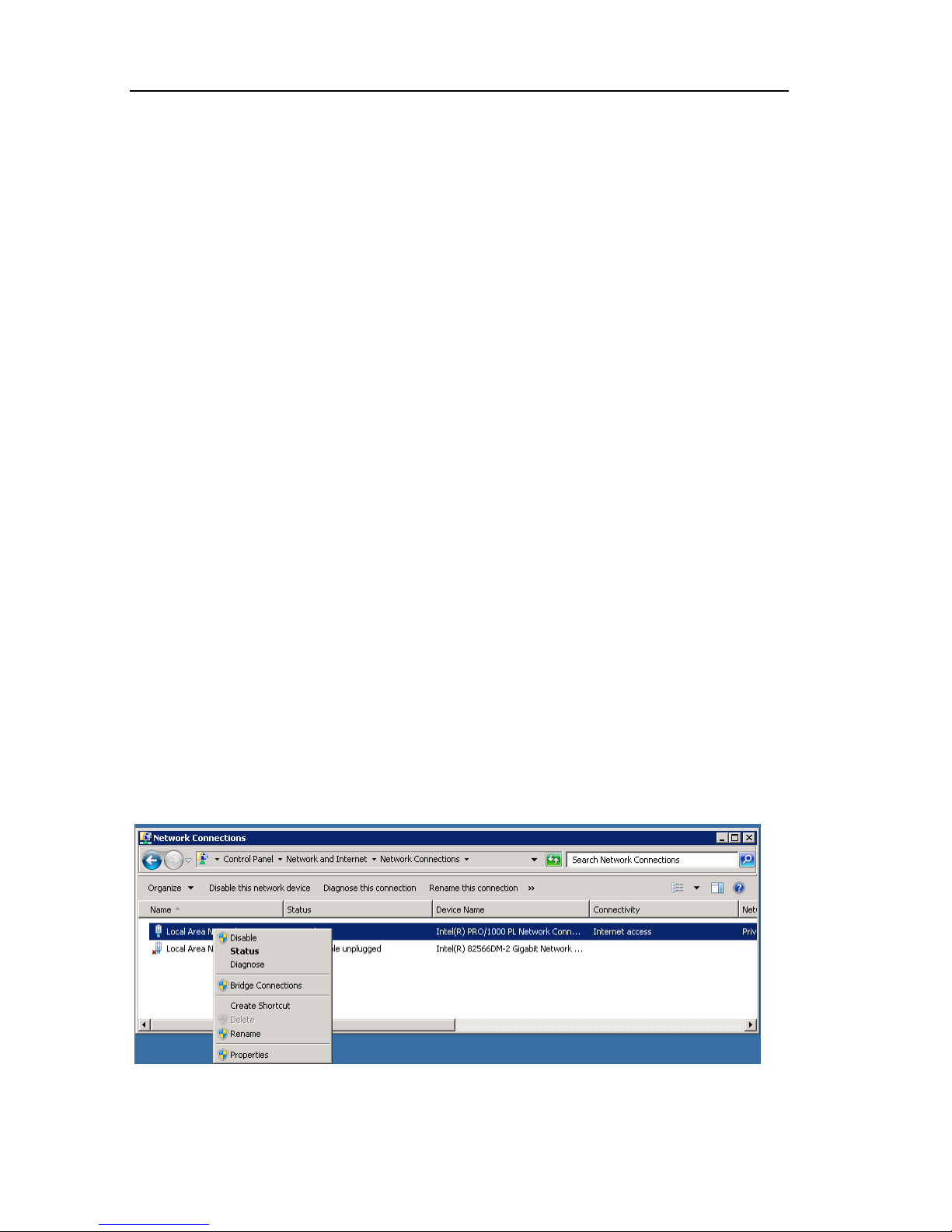
6.1 IP Configuration - Graphical User Interface
1. Using the mouse or keyboard and the Windows GUI
click on the “Start” menu
2. Select “Control Panel”
3. Click “View Network status and tasks”
4. Click “Change adapter settings.” A list of network
adapters will be displayed. Right-click on the network
adapter you would like to configure and choose
“Properties”.
The “Connection Properties” window will appear
Table of contents
Other Streambox Media Converter manuals


Popular Media Converter manuals by other brands


Speaka Professional
Speaka Professional 98 92 86 operation instruction

Extron electronics
Extron electronics QSD 204 user manual

Roland
Roland ASC-10 owner's manual

Sollae Systems
Sollae Systems CSW-H85F user manual

Elatec
Elatec TCPConv 2 Technical manual

Tehnologistic
Tehnologistic Train-O-Matic Lokommander II Next18 ECU user manual

DOREMIDI
DOREMIDI MIDl THRU-6 Pro Box instructions

Metronome
Metronome AQWO owner's manual

Hagstrom
Hagstrom KE-USB36FS user manual

Contemporary Research
Contemporary Research QMOD-SDI HDMI product manual

Progressive Dynamics
Progressive Dynamics PD9200 SERIES owner's manual

Digi
Digi Edgeport/1 installation guide