StreetStrider 8s User manual

1
Copyright © 2019 StreetStrider International, LLC
8s OWNER’S MANUAL
1-800-348-0998 | www.StreetStrider.com
Copyright © 2019 StreetStrider International, LLC
2Copyright © 2019 StreetStrider International, LLC
Owner’s Manual Contents
About This Manual............................................
Parts Identication............................................
Assembling the StreetStrider 8s........................
Unpacking and Prep..................................
Front Wheels............................................
Rear Wheel...............................................
Poles and Skis................................... ........
Brakes.......................................................
Rear Hub Shifter................................ ........
Frame Strut..............................................
Front Wheel Alignment.............................
Advanced Lean-to-Steer Technology..........
Folding.....................................................
Simple Steps to Learn to Stride.........................
Safety Equipment..............................................
Mechanical Safety Check...................................
Return Policy.....................................................
Limited Warranty...............................................
3
4
8
8
8
9
10
13
14
15
16
17
19
20
22
24
25
26
1
2
3
3.1
3.2
3.3
3.4
3.5
3.6
3.7
3.8
3.9
3.10
4
5
6
7
8

3
Copyright © 2019 StreetStrider International, LLC
Records
About This Manual
1
Record your StreetStrider model, serial number (on the frame just behind
the underside of the bottom bracket; see photo) and other information
below. Retain your sales receipt as proof of purchase.
This StreetStrider 8s Owner’s Manual contains important assembly, maintenance, safety and performance information. It was
written to help you get the most performance, comfort, enjoyment and safety out of your new StreetStrider. Keep this manual
handy for future reference.
IMPORTANT: If your StreetStrider was purchased unassembled, read this manual before you assemble it. The Limited Warranty
found in this manual on page 26 applies only to StreetStriders that comply with the assembly instructions in this Owner’s
Manual.
IMPORTANT: You should read this manual before you go out on your rst ride.
Riding a StreetStrider can be a hazardous activity even under the best of circumstances. It is highly recommended that your
rst stride on your new StreetStrider be taken in a controlled environment, away from cars, obstacles and other cyclists, and
wearing your helmet.
Proper maintenance of your StreetStrider is your responsibility as it reduces the risk of injury. This manual contains many
IMPORTANT, CAUTION and WARNING statements concerning the consequences of failure to maintain or inspect your
StreetStrider. When inspecting your StreetStrider, be certain to secure all parts properly as described in Table 2-1. Under-
tightening or over-tightening can result in component damage. StreetStrider parts have metric hardware - always use the
correct tools.
IMPORTANT: It is impossible to predict every condition that will occur while striding. StreetStrider (the Company) has made
no representation about the safe use of the StreetStrider under all conditions. There are risks associated with the use of any
StreetStrider that cannot be predicted or avoided, and the Company recommends safe and cautious striding.
WARNING Failure to read and comply with all assembly, safety, performance and maintenance
requirements and warnings, and unsafe or improper use of the StreetStrider could result in serious
injury or death.
Register your StreetStrider online at www.StreetStrider.com so we can notify you about new models, care and maintenance
issues, and record your serial number. You may also want to register your serial number with your local police department in
the event that your StreetStrider is lost or stolen.
MODEL COLOR SERIAL NUMBER
DATE OF PURCHASE PLACE OF PURCHASE

4Copyright © 2019 StreetStrider International, LLC
Parts Identication
2
Figure 2.1 StreetStrider 8s Parts. Refer to Table 2-1 for part numbers and descriptions.
5
Copyright © 2019 StreetStrider International, LLC
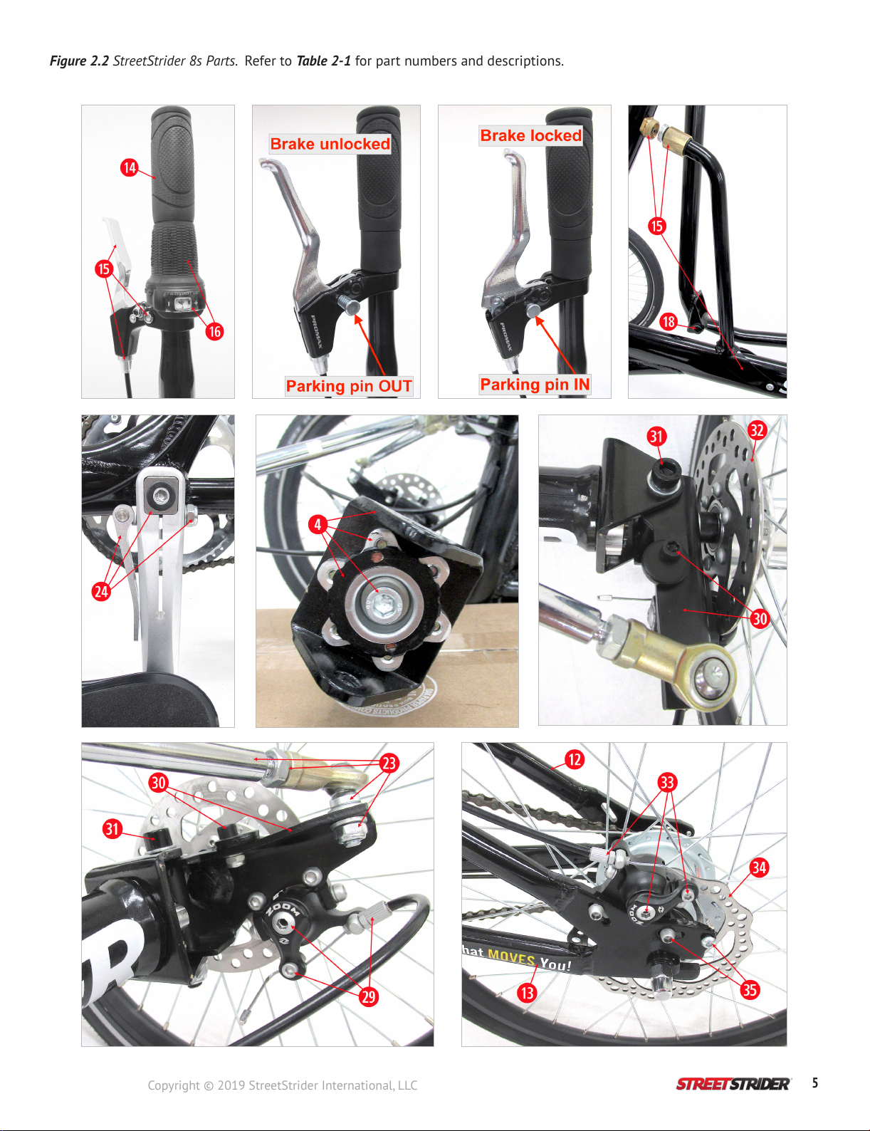
Figure 2.2 StreetStrider 8s Parts. Refer to Table 2-1 for part numbers and descriptions.

6Copyright © 2019 StreetStrider International, LLC
#DESCRIPTION HARDWARE SPECIFICATIONS QTY STATE
1Main frame bone AL 6061 T6 1
2Head tube Bottle cage bosses
Strut coupling boss M5 x P0.8 threads, 2 front side, 1 rear side 2 Tighten to secure
cage and coupling
3Crossbar 1
4Front beam Clevis bracket with
adjustable caster angle
Male and female 52 tooth spline
M31 x P1.0 lock ring
M10 x P1.5 x L20 x W8, center screw
2
Tighten after
adjusting caster
angle
5Fold joint Quick Release clamp stem
nylon lock nut M6 x P1.0 x L20 x H10 x W10 1 Snug to secure
6Stride pole upper Left and right side 2
7Strider pole lower 2
8Frame strut Coupling at top end
Saddle at bottom end
¾” x 11.5 TPI GHT, M5 x P0.8 inner face
M5 x P0.8 binding screw w/ nylon washers
1
1
Tighten
Snug
9Strider ski Composite bushings
Roller bearings
OD12 x ID10 x L15 x 17 mm ange, at Joint #2
OD 26 x ID 18 x L 20, at Joint #3
4
4
Grease
Grease
10 Foot platform 4 mm hex screw,
Grip tape on surface M5 x P0.8 x L12 x H12 x W4, 12 Tighten
11 Rear fender frame 4 mm hex screw, M5 x P0.8 threaded hole for luggage rack 1 Tighten
12 Fender stay 2
13 Chain stay 2
14 Hand grip Left and right side, rubber 2
15 Twist grip shifter 3 mm hex screw M4 x P0.7 x L16 x W3, clamp 1 Tighten
16 Brake lever
5 mm hex screw
Parking pin
Cable housing adjuster
Cable doubler
M5 x P0.8 x L20 x H10 x W5, clamp
OD 10, spring loaded
M10 x P2.0 barrel adjuster with lock ring
Front brake, with adjuster and lock ring
2
2
2
1
Tighten
Adjust-lock
Adjust-lock
17 Joint #1, cross bar-pole
pivot clamp assembly
4 mm hex screw
3 mm hex set screw
4 mm hex pan head
Roller bearings
4 mm at head screw
M5 x P0.8 x L30 x H8 x W4, clamp cap
M6 x P1.0 x L5 x W3, with cup end, cross bar
M6 x P1.0 x L10 x W4, lock screw
OD26 x ID18 x L20, in cross bar
M6 x P1.0 x L20 x W4, inner shaft end
8
8
2
4
2
Tighten evenly to
secure pole
Tighten
Tighten
Grease
Tighten
18 Joint #2, pole-ski pivot
8 mm hex screw,
washer,
17 mm nut
M10 x P1.5 x L75 x H15 x W8
OD16 x ID10 x T1
M10 x P1.5 x L10 x W17, nylon lock
2
2
2
Snug but allow joint
movement
19 Joint #3, ski-pedal pivot 6 mm hex spindle OD18 X L60 x W6, 9/16” x 20 TPI
Right threads right, Left threads left, C clip 2 Tighten
20 Front beam pivot
8 mm hex screw
3 mm hex set screw
Tapered roller bearing
M10 x P1.5 x L20 x W8, front cap
M6 x P1.0 x L5 x W3, rear end
OD 47 x ID 20 X T15
1
1
2
Tighten
Tighten
Grease
Figure 2-1 StreetStrider 8s Parts List with Hardware Specications.

7
Copyright © 2019 StreetStrider International, LLC
#DESCRIPTION HARDWARE SPECIFICATIONS QTY STATE
21 Front wheel rim and tire Rim 36H, Tire 16” x 1 3/8”, ISO 37 x 349 2 80-85 psi
22 Front wheel hub 19 mm hex axle nut M12 x P1.75 x L10 x W19, nylon lock 2 Tighten
23 Steering linkage
Inboard and outboard
rod ends
Threaded linkage rod
M8 x P1.25 x L20 x W14 ats on stud
M8 x P1.25 x L10 x W13 nylon lock nut
M8 x P1.25 x L20 rod, right and left thread ends
M8 x P1.25 x L5 x W14, right and left jam nuts
4
2
4
Lubricate balls
Tighten
Tighten
Tighten
24
Crank arm set with quick
release left side
Bottom bracket
8 mm hex screw
QR stem
Square taper
M8 x P1.0 x L15 x H12 x W8, 18 mm ange
M10 x P1.5 x L10 x W17, nylon lock
68 x 122 mm
2
1
1
Tighten
Snug
Tighten
25 Chain ring with guard 52 T 1
26 Chain 1/2” x 1/8” x 93 links 1 Lubricate
27 Rear wheel rim and tire Rim 36 H, Tire 20” x 1 3/8”, ISO 37 x 451 1 80-85 psi
28 Internal gear hub 15 mm axle nuts 8 speed, 3/8” x 26 TPI x W15 axle nuts 2 Tighten
29 Front disc brake
5 mm hex mount screw
5 mm hex caliper screw
5 mm hex outer pad
3 mm hex inner pad
Cable housing adjuster
4 mm hex cable clamp
M6 x P1.0 x L15 x H10 x W5, through knuckle
M6 x P1.0 x L15 x H10 x W5, through bracket
W5 outer pad adjuster with 2 mm lock set screw
W3 inner pad adjuster, through center screw hole
M6 x P1.0 x L15 knurled for ngers with lock ring
M5 x P0.8 x L12 x H10 x W4, socket and nut
4
4
2
2
2
2
Tighten
Adjust-tighten
Adjust-tighten
Adjust
Adjust-lock
Adjust-tighten
30 Steering knuckle w/
lean stop
5 mm hex screw
Lean stop disc
Composite bushing
M6 x P1.0 x L15 x H10 x W5, socket screw
W10 nylon lock nut
OD24 x T4 with 6 mm offset hole
OD12 x ID10 x L15 x 17 mm ange
2
4
Adjust-tighten
Grease
31 King pin bolt in front beam
clevis
8 mm hex bolt
washer
17 mm nut
M10 x P1.5 x L75 x H15 x W8, socket
OD16 x ID10 x T1
M10 x P1.5 x L10 x W17, nylon lock
2
4
2
Snug but allow
knuckle swivel
32 Front disc rotor 4 mm hex screw M5 x P0.8 x L10 x H10 x W4, Rotor 120 mm 12 Tighten
33 Rear disc brake
5 mm hex mount screw
5 mm hex caliper screw
5 mm hex outer pad
3 mm hex inner pad
Cable housing adjuster
4 mm hex cable clamp
M6 x P1.0 x L15 x H10 x W5, through drop out
M6 x P1.0 x L15 x H10 x W5, through bracket
W5 outer pad adjuster with 2 mm lock set screw
W3 inner pad adjuster, through center screw hole
M6 x P1.0 x L15 knurled for ngers with lock ring
M5 x P0.8 x L12 x H10 x W4, socket and nut
2
2
1
1
1
1
Tighten
Adjust-tighten
Adjust-tighten
Adjust
Adjust-lock
Adjust-tighten
34 Rear disc rotor 4 mm hex screw M5 x P0.8 x L10 x H10 x W4, Rotor 140 mm 6 Tighten
35 Rear drop out
Dropout slot for rear hub axle
Holes for rear brake mounting bracket
M5 x P0.8 hole for rear luggage rack screw
2
4
2
Specication
Key
M=OD of threads, mm L=length W=wrench t, mm
P=pitch, threads/mm H=OD of head T=washer thickness, mm
TERMINOLOGY: The right and left sides of the StreetStrider refer to sides when one is striding.
IMPORTANT: Save the box and packing material as they must be used to repack the StreetStrider for any returns.

8Copyright © 2019 StreetStrider International, LLC
Assembling the
StreetStrider 8s
Unpacking and Prep (see video)
3
3.1
To assemble your StreetStrider 8s, rst follow the steps and photos in this manual and view the StreetStrider 8s assembly videos where
indicated. Included in the shipping box are the StreetStrider 8s in parts, an Owner’s Manual [1] and a small bundle in the top tray inside the
box containing a tool kit [2] which includes, four open end wrenches 17 x 14, 15 x 13, 14 x 12, and 13 x 10 mm [3], seven hex wrenches 8,
6, 5, 4, 3, 2.5, 2 [4], two tire levers [5], a 19 mm front hub socket [6], and a front wheel caster spanner wrench [7]. The parts bags contain the
front beam shaft assembly [8], a right crank arm screw [9], the shifter cassette parts [10], three wheel reectors [11], two front brake cable
tips [12], zip ties [13], touch up paint [14], and two spare inner tubes [15], Figure 3.1.2.
Figure 3.1.1 The StreetStrider box shows which
side is up. You will need a blade or scissors,
pliers, tape measure, grease and a rag.
Figure 3.1.4 The main frame assembly,
padded and secured with zip ties, is on the
bottom cardboard panel which has corner
cut-outs.
Figure 3.1.2 The top tray in the box holds
the parts bundle and the support layers
underneath protect the StreetStrider.
Figure 3.1.5 Grip the corner cut-outs and
lift that panel and the folded StreetStrider
out of the box, set the unit on a table, and
remove the remaining zip ties.
Figure 3.1.3 The front wheel assembly and
rear wheel are the next 2 layers. Remove the
wheels and set aside.
Figure 3.1.6 Once all the packing is removed
set the foot platform assemblies (lower pole,
ski, foot platform, crank arm) aside.
Front Wheels (see video)
3.2
Figure 3.2.1 Lay the frame on it’s left side.
Retrieve the front beam shaft assembly,
take the cap, tapered bearings and back
plate off the shaft, and get the 8 and 3 mm
hex wrenches.
Figure 3.2.2 Loosen the set screw under
the front beam shaft tube with a 3 mm hex
wrench. Slide the shaft into the tube so that
the at section on the rear end of the shaft
ts just above the 3 mm.
Figure 3.2.3 With the shaft inserted all the way
forward, secure the shaft by tightening the set
screw with the 3 mm hex wrench.

9
Copyright © 2019 StreetStrider International, LLC
Figure 3.2.4 With the frame
upright, slide the back plate and
one of the tapered bearings,
with taper facing forward, onto
the shaft. Grease the bearings.
Figure 3.2.8 Lower the left
steering linkage so the outboard
rod end can be attached to the
left steering knuckle.
Figure 3.2.5 Unfold the front
wheels on the front beam and
set the front wheel assembly in
front of the shaft.
Figure 3.2.9 Unscrew the 13 mm nylon lock nut from the rod end
stud, insert the threaded stud through the hole at the forward end of
the steering knuckle, secure the stud with the nylon nut having one
washer above and one washer below the knuckle and then hold the
stud and tighten the nut using two 13 mm wrenches.
Figure 3.2.6 Grease the front
bearing race in the front beam.
Figure 3.2.7 Insert the other
bearing onto the shaft with the
taper facing rearward. Put the
cap over the front of the beam
shaft, insert the 10 mm screw, and
tighten with the 8 mm hex wrench.
Figure 3.2.10 Repeat steps
to attach the right steering
linkage.
IMPORTANT: We recommend adding a liquid thread locker to the threads of the 10 mm screw.
Figure 3.2.11 Route the front brake cables
from the head tube, under the steering
linkage and over the front beam. If the cable
housing is off of the cables slide it back on.
Insert the left and right cable and housing
into the barrel adjuster on the left and right
brakes, respectively.
Rear Wheel (see video)
3.3
Figure 3.3.1 Remove the silver
acorn nut and gray (or yellow)
non-turn washer from the right
axle end.
Figure 3.3.2 From the parts bag retrieve the shifter cassette parts,
the cassette pulley, the driver cap ring (often in the rear side of the
pulley), and the lock ring. Press the driver cap over the hub driver
until it snaps down.
Figure 3.3.3 Place the cassette
pulley over the axle so that the
red dots on the washer and the
cassette pulley are in line.

10 Copyright © 2019 StreetStrider International, LLC
Poles and Skis (see video)
3.4
Figure 3.3.4 Put the lock ring onto the
cassette pulley so that the 2 yellow dots are
adjacent.
Figure 3.3.5 Rotate the lock ring 45°
clockwise to lock the cassette pulley onto
the hub.
Figure 3.3.6 Replace the non-turn washer with
tongue pointing rearward, and screw the acorn
nut back onto the axle a few turns.
Figure 3.3.7 Remove the plastic brace in the
rear drop and loop the chain over the rear
drop out and the bottom bracket, BB.
Figure 3.3.8 Unscrew acorn nuts on each end
of the axle so there is an exposed section of
axle under the non-turn washers that can
slide into the dropouts. On the left side, align
the brake rotor with the brake caliper gap.
Figure 3.3.9 Slide axle into dropouts all
the way forward, align the tongue of the
non-turn washers with dropout slots, nger
tighten the acorn nuts on both ends, and
loop chain around hub sprocket.
IMPORTANT: Inate tires to 80-85 psi.
Figure 3.4.1 While the head tube is
folded onto the main frame, use the
4 mm hex wrench to remove the 4
screws and caps from the both pole
clamps at Joint #1.
Figure 3.4.2 Apply a little
grease to the screw heads
and threads then set the
caps with screws on the
table.
Figure 3.4.3 Raise the head tube while sliding the quick release, QR,
clamp pin to the right. With the head tube in the full upright position
allow the clamp pin to insert into the hole.

11
Copyright © 2019 StreetStrider International, LLC
Figure 3.4.4 Rotate the QR stem to the
vertical position so that the lever is
against the head tube then close the
lever downward.
Figure 3.4.5 Retrieve the right foot platform assembly
(lower pole, ski, foot platform, and crank arm with chain
ring) and position next to right side of the frame. Make
sure the chain is looped over the BB spindle.
Figure 3.4.6 Rotate the BB spindle
so that the upper surface of the left
rectangular end piece on the spindle has
the shallow channel and is horizontal.
Figure 3.4.7 Lift the right crank arm so it is in the 6 o’clock
position and insert it onto the BB square spindle. Using the
8 mm hex wrench, screw the crank bolt into the spindle and
tighten to 30 ft lb, then wrap the chain around the chain ring.
Figure 3.4.8 Lift the right lower pole and t it into the right Joint #1 clamp
base. Place the Joint #1 cap with greased screws over the pole and using the 4
mm hex wrench, screw each the 4 caps screws in about 5-10 turns. Add a little
grease to the inner surface of the lower pole.
IMPORTANT: Make sure there is a little grease on the spindle so the crank arm slides on rmly.
Figure 3.4.9 Apply a little grease to the lower section of the right upper
pole, which has a brake lever and shifter, then slide it into the lower
pole to a level that ts the height of the user. The upper pole can also
be rotated toward the side to provide a comfortable width for the user.
Figure 3.4.10 The pole height lines
are used to set the approximate pole
height for the height of the user, from
< 5’ to approximately 7’.
Figure 3.4.11 With the 4
mm hex wrench, carefully
tighten the Joint #1
clamp in an X pattern so
that all the screws are
tightened evenly and the
space between the clamp
base and cap on the front
side of the pole is equal
to the space on the rear
side.
IMPORTANT: A good starting pole height will position the user’s arm to have a 90°
elbow bend, with forearm parallel to the ground when standing on the platforms and
holding the grips of both poles in vertical position.

12 Copyright © 2019 StreetStrider International, LLC
Figure 3.4.12 Place the left ski assembly on
the left of the frame, rotate the right crank
to the 12 o’clock position and rest the left
upper pole on the right foot platform.
Figure 3.4.13 Lift the left crank arm to to
the 6 o’clock position and open the QR lever.
Note that the QR stem, visible in the crank
arm opening, will t into the channel of the
BB end piece and lock the crank onto the BB.
Figure 3.4.14 SRotate the QR lever 180° so
the at face of the QR stem is visible in the
crank arm opening, which will allow the
opening to slide over the BB end piece.
Figure 3.4.15 Slide the crank arm
opening over the BB end piece
as far as possible.
Figure 3.4.19 Attach the lower and upper pole on the left
side following the procedure used on the right side. Make
sure the left and right poles are set to the same height,
rotate the poles to approximately shoulder width of the
user and also parallel from the side view.
Figure 3.4.16 Rotate the QR lever
180° so that the QR stem ts
into the BB end piece channel.
Figure 3.4.17 Close the QR lever
against the crank arm.
Figure 3.4.20 Rotate the brake levers to a forward position, rotate the
shifter so the gear indicator window is seen by the user, tighten the
brake lever clamps with the 5 mm hex wrench and the shifter clamp
with the 3 mm hex wrench. Use 2 of the zip ties to orderly hold the
cables to the poles.
Figure 3.4.18 If the QR lever
closes without any resistance
open the lever, pull the crank
arm off the BB ¼ inch (6 mm),
tighten the 17 mm stem nut ¼
turn, push the crank arm back
on, and close the QR lever. If
needed, repeat until QR closes
with some resistance.
IMPORTANT: A good starting pole height will position the user’s arm to have a 90° elbow bend, with forearm parallel to the
ground when standing on the platforms and holding the grips of both poles in vertical position.

13
Copyright © 2019 StreetStrider International, LLC
Brakes (see video)
3.5
Figure 3.5.2 Fold the head tube down and push the cable housing from the left brake lever into the opening at the top of the crossbar so
that the base of the cable doubler is visible through the hole in the fold joint. While pulling the cable down at the caliper make sure there
is no exposed cable visible at the brake lever by inserting the cable housing ferrules into the brake lever barrel adjuster. Also, insert the
cable housing ferrules into the base of the cable doubler using the pliers if needed.
Figure 3.5.1 Make sure the brake rotor is centered in the caliper gap between the pads and the wheel spins freely. If adjustment is needed,
loosen the caliper positioning screws with a 5 mm hex wrench, tighten the inner pad with the 3 mm hex wrench, inserted through the
caliper lever, and the outer pad with the 5 mm hex wrench to center the rotor in the gap, then tighten the positioning screws. If the rotor is
already centered in the caliper gap tighten the pads against the rotor in order to attach the brake cable in the next steps.
Front Brakes
Figure 3.5.3 Loosen the clamping screw with the 4 mm hex wrench so there is space to route the brake cable under the nut. Grip the brake
cable end with pliers, rotate the pliers to make the cable taut, then tighten the cable clamping screw. Unscrew the inner and outer brake
pads so that a sliver of light can be seen between the rotor and pads and so the wheel spins freely. Bend the cable away from rotor and
squeeze a cable tip onto the end of each cable. Repeat on the other brake.
To make sure both front brakes stop equally, stand in front of the StreetStrider, squeeze the left brake lever and pull the StreetStrider
forward while slowly easing the brake pressure. If one wheel starts rotating before the other, which begins to turn the StreetStrider, adjust
the brake pads and/or the barrel adjuster at the caliper until that wheel begins to rotate with the other wheel.
IMPORTANT: Properly adjusted brakes will clamp the wheels when the brake lever is squeezed
and about 1 inch (25 mm) from the rubber grip.

14 Copyright © 2019 StreetStrider International, LLC
Rear Hub Shifter (see video)
3.6
Rear Brake
Figure 3.5.4 With the chain wrapped around
both the right crank arm chainring and
the rear hub sprocket, pull the rear wheel
backwards to make the chain taut, center
the front of the wheel in the frame chain
stays, and tighten the acorn nuts with the 15
mm wrench, rst right side then left. A taut
chain should only move about ½” if lifted at
a point midway between the chain ring and
hub sprocket.
Figure 3.5.5 The rear brake
caliper is adjusted exactly as
described for a front brake
caliper.
Figure 3.5.6 Both
brake levers have a
parking brake pin
to hold the brake
lever in a squeezed
position. If the
parking brake does
not hold, unscrew
the brake lever
barrel adjuster.
Figure 3.5.7 To install the 3 wheel
reectors onto the spokes, position
the reector between spokes and
rotate so the reector ends snap
around the spokes.
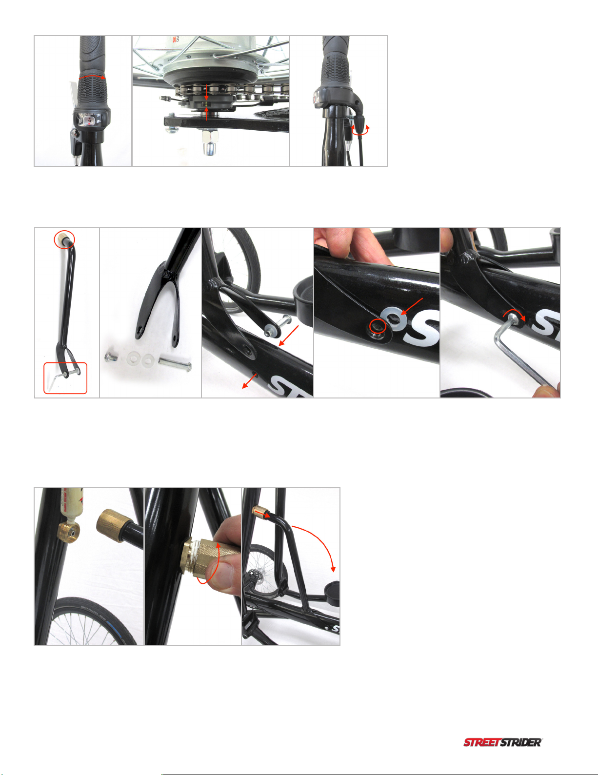
Figure 3.6.1 At the grip on the right pole, twist the
shifter to gear 1. At the rear hub, pull the shifter
cable taut and make sure the length of cable from the
ferrule to the center of the clamping screw is 101 mm
(4 in). If not, loosen the nut with the 10 mm wrench,
adjust to 101 mm and tighten.
Figure 3.6.2 Slide the ats of the clamping screw with nut facing outward into the
oblong slot at the 10 o’clock position of the cassette pulley. Ease the shifter cable
housing forward through the frame so the shifter cable lies in the pulley groove
from the 10 to 6 o’clock position. Insert the 2 mm hex wrench into the tab with a
hole at the 9 o’clock position of the pulley and rotate the spring-loaded cassette
pulley ¼ turn counter clockwise.
Figure 3.6.3 While holding the wrench at the 6
o’clock position pull the shifter cable housing
forward until the cable can be slid into the slot
of the arm of the cassette pulley, push the black
plastic ferrule on the end of the cable housing
into the socket, then return the wrench to the
9 o’clock position making sure the cable lies in
the groove under the cassette pulley.
15
Copyright © 2019 StreetStrider International, LLC
Frame Strut (see video)
3.7
Figure 3.6.4 To check gear alignment,
twist the shifter to gear 4 and make
sure the 2 yellow lines in the cassette
pulley window are in line. If the lines
are offset use the barrel adjuster nut at
the shifter to move the lines into the
correct position.
Figure 3.7.2 Add some grease to the threads of the
brass receiver attached to the rear side of the head
tube, press the brass collar over the receiver and
tighten. To fold the head tube down the brass collar
is disconnected from the receiver and the strut folded
backwards pivoting at the saddle screw.
Figure 3.7.1 Retrieve the frame strut, which has a brass threaded collar at the top and frame saddle at the bottom. Using the 5 mm hex
wrench, unscrew and separate the binding screw and the 2 nylon washers. Insert the longer female end of the screw through the hole at the
end of the right side of the saddle and add a nylon washer on the inner side of the saddle. Align the saddle and screw with the frame hole
and push the screw through the hole until it appears in the frame hole on the left side. Slide the second nylon washer between the saddle
and the frame and over the screw end. Insert the male screw and tighten the screw with the 5 mm hex wrench. the receiver and tighten.
16 Copyright © 2019 StreetStrider International, LLC
Front Wheel Alignment (see video)
3.8
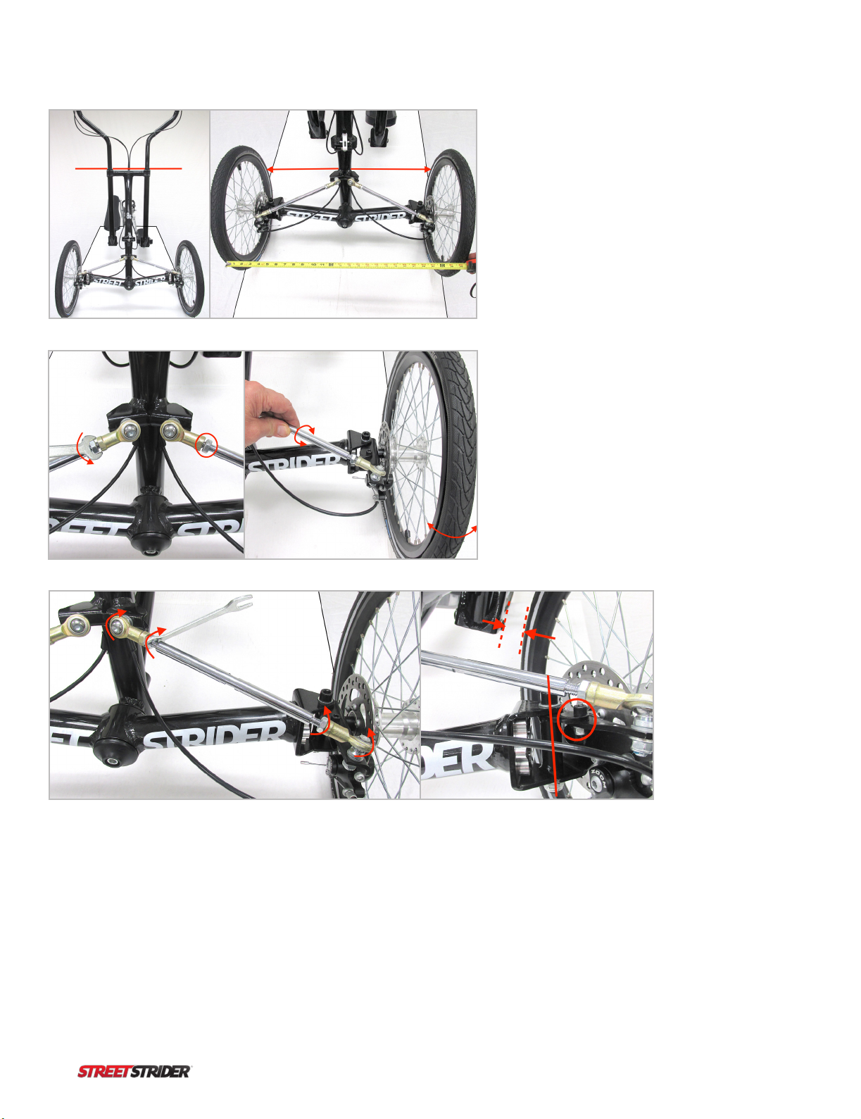
Figure 3.8.1 The front wheels should be aligned/parallel so
they do not point in (toe in) or point out (toe out). Alignment
is important for performance so take the time to do it
correctly. Inate the tires, 80-85 psi, set the StreetStrider
upright, not leaning, on a level surface. Making the crossbar
parallel to a horizontal line behind the StreetStrider, such
as a shelf or window will ensure it is not leaning. Parallel
lines on the surface such as a table edge will help to see if
wheels are parallel. Measure the distance from the center
rib of one tire to the center rib of the other tire on both
the front or leading edge and the rear or trailing edge. The
distances should be near 26 inches and should be equal to
each other within 1/8” or 3 mm.
Figure 3.8.3 When the wheels are parallel to within 1/8” or 3 mm,
tighten the jam nuts against the rod ends. To tighten the jam nuts,
rst rotate both rod ends as far as possible in the direction that
the jam nuts will tighten, then use the 14 mm wrench to tighten
the jam nut against the rod end. Check to make sure that each
steering linkage rod is free to rotate as the StreetStrider is leaned
to each side.
Figure 3.8.2 If the distances are not equal to each other,
use the 14 mm open end wrench to loosen the jam
nuts that are tightened against the base of each rod
end. On each steering linkage, one rod end has right
hand threads and the other has left hand threads, so
make sure to turn the jam nuts in the correct direction
to loosen. Rotate the linkage rod one way or the other-
note how the tire angle changes - until the distance
between the tire center ribs in the front is equal to that
in the rear and the wheels are parallel while making
sure that the cross bar stays horizontal. Any adjustment
to the right linkage rod should be duplicated on the left
linkage rod to maintain symmetry.
Figure 3.8.4 To increase resistance to
leaning, the King Pin bolt (red line) can
be tightened with the 8 mm hex and 17
mm open end wrenches. To change the
lean angle degree, adjust the position of
the lean stop disc (circle) on the steering
knuckle with the 5 mm hex and 10 mm
open end wrenches. The left lean stop disc
regulates the right lean angle and the right
stop disc regulates the left lean angle.
When adjusting the lean angle make sure
the tire clears the pole by 1 inch, 25 mm.
IMPORTANT: Do not over tighten and strip the thin jam nut
17
Copyright © 2019 StreetStrider International, LLC
Advanced
Lean-to-Steer
Technology (see video)
3.9
To steer vehicles with 2 front wheels, the wheel hub connected to the steering knuckle turns or pivots on a mostly vertical axis/component
called the King Pin. The upper end of the King Pin axis can be angled backward and that angle is called the caster angle. At the angle
limits, a vertical King Pin would have a caster angle of 0° and a horizontal King Pin would have a caster angle of 90°. The caster angle
controls the way a wheel can steer. At 0° caster angle, the wheel pivots on a vertical axis to steer right or left and this type of steering is
called toe. At 90° caster angle, the wheel pivots on a horizontal axis and can only lean left or right and this is called camber. As the caster
angle is increased the front wheels will steer with less toe and more camber.
In most vehicles with a low center of gravity, such as automobiles and recumbent tricycles, the caster angle is typically about 3-6°,
which increases steering stability compared to 0° caster. Large camber lean is not necessary because the center of gravity is low and
the probability of tipping over in a turn at speed is low. However, when the center of gravity is higher, as when standing upright on a
StreetStrider, being able to lean into a turn at speed is necessary so the StreetStrider lean-to-steer system is designed to combine both toe
steering and camber.
The StreetStrider 8s is the rst model with a user-adjustable caster angle of the King Pin providing more stability for the novice at low
caster angles or more performance at speed for the professional at higher caster angles. At the end of the front beam the King Pin bolt
passes through the clevis bracket and steering knuckle. On the 8s the ends of the front beam have a 52 tooth male spline and the clevis
bracket ts onto the end of front beam with a 52 tooth female spline. Accordingly, each spline tooth rotation of the clevis bracket is
approximately a 7° change in caster angle. A low caster angle, 10 – 20° allows the wheels to mostly toe steer, which provides increased
stability at low speed. A higher caster angle, 30-50° allows much more camber, which increases leaning and performance at higher speeds
although the trade off is a bit less stability at low speed. The illustrated instructions below show how the StreetStrider 8s caster angle can
be adjusted to suit the desire and ability of the user.
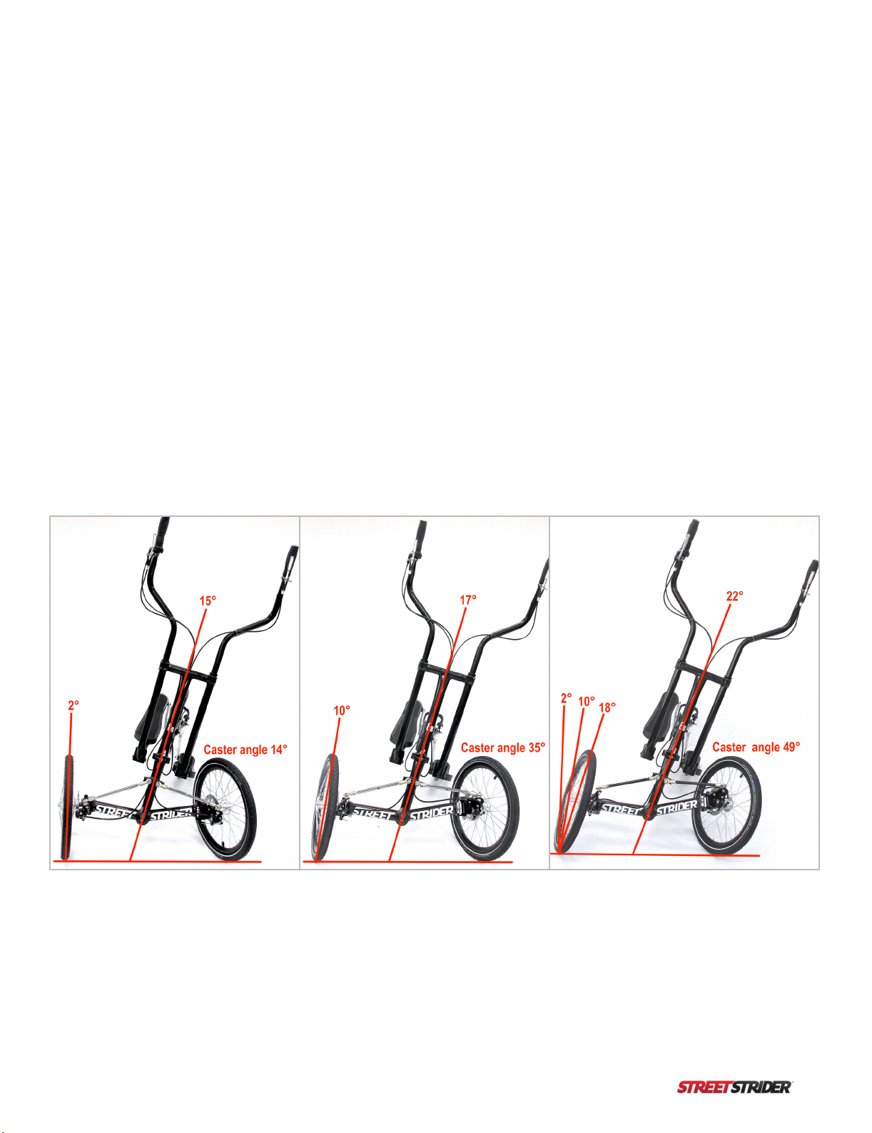
Caster Angle and Wheel Camber
Figure 3.9.1 By setting the caster angle at 14° the StreetStrider frame can lean about 15° but the outer front wheel will only camber about
2°. Most of the steering results form a change in toe angle. At 35° caster angle the frame leans about 17° and the outer wheel has more
camber to about 10°. At 49° caster angle the lean increases to 22° and the outer front wheel cambers to 18°. In a turn, the inner wheel toe
angle and camber lean is a bit more than the outer wheel.
18 Copyright © 2019 StreetStrider International, LLC
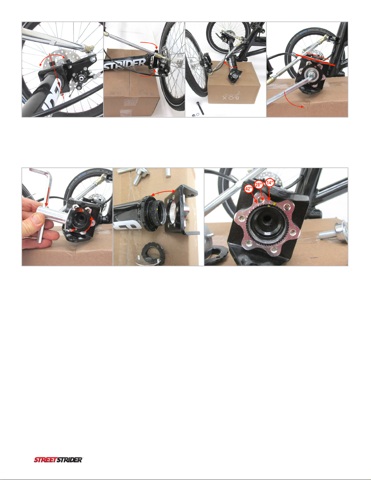
Figure 3.9.2 The caster angle of
the King Pin can be set at lower
or higher values.
Figure 3.9.6 Use the clevis
spanner wrench with the 8 mm
hex wrench as lever to unscrew
the lock ring.
Figure 3.9.3 Lift one side of the
front beam so the wheel is off
the table. Unscrew the King Pin
bolt with the 8 mm hex wrench
and the 17 wrench.
Figure 3.9.7 Slide the clevis
bracket female spline off the
male spline.
Figure 3.9.4 Slide the steering
knuckle out of the clevis bracket
and move the front wheel
assembly forward.
Figure 3.9.8 On the left side both the male and female
splines have a yellow dot at top center. Right side has red
dots. If those 2 dots are aligned, the clevis caster angle will
equal 0°. Each spline tooth is also a 7° angle change. The
small indentations in the female spline are every 2 teeth or
14°. Any adjustment to caster angle on one clevis must be
duplicated at the other clevis so they remain parallel.
Figure 3.9.5 Unscrew the center
bolt with the 8 mm hex wrench.
Note that the surface of the
clevis bracket on each end of
the front beam are parallel.
IMPORTANT: After caster angle adjustment the front wheels MUST be realigned
19
Copyright © 2019 StreetStrider International, LLC
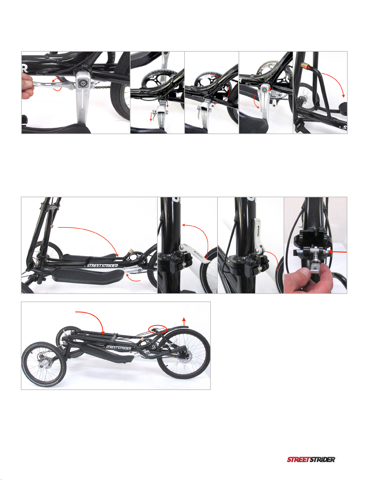
Folding (see video)
3.10
Figure 3.10.1 Stabilize the StreetStrider
by engaging the right parking brake pin
to lock the rear brake. From the left side
of the StreetStrider, rotate the left crank
arm to the 6 o’clock position, lift the quick
release lever, rotate the lever 180° and
lower it to the left side of the crank arm.
Figure 3.10.2 Pull the crank arm off the BB spindle just to where
the BB end piece can be rotated 180° so the right crank can also be
rotated to the 6 o’clock position. Insert the crank arm over the end
piece, lift the QR lever and rotate 180° then push the lever back down
the side of the crank arm.
Figure 3.10.3
Unscrew the brass
coupling at the top
of the strut and fold
it back ward to the
main frame.
Figure 3.10.4 Rotate the crank arms forward so the foot
platforms are horizontal. Lift the QR lever of the head
tube fold joint up and rotate the stem forward. With
one hand supporting the head tube, pull the QR stem
to the right side so the pin disengages from the hole
and lower the head tube down. With the rear brake
locked the strider can be lifted by the rear fender and
rolled or stood up against a wall for storage.
20 Copyright © 2019 StreetStrider International, LLC
Safety rst.
Find a safe, at place.
Become familiar with the brakes and grip shifter.
Step on and start rolling.
Find the best gear.
Lean to steer.
Have fun!
STEP 1
STEP 2
STEP 3
STEP 4
STEP 5
STEP 6
STEP 7
Simple Steps to Learn to Stride
4
Before you stride, wear a CPSC (Consumer Product Safety Commission) approved helmet. Children under 18 years old must
wear helmets in some states. At night, make sure to wear light colored and/or reective clothing and equip your StreetStrider
with front and rear lights. Before starting any exercise program, check with your doctor to make sure you are physically healthy
enough.
An ideal location to practice striding is a large at area such as a parking lot with little to no trafc.
Straddle your StreetStrider with both feet on the ground and practice squeezing the front brake lever at the left grip and
the rear brake lever at the right grip. At the right grip, rotate the grip shifter clockwise to shift to a lower gear and counter
clockwise to shift to a higher gear. To start striding on a at place, rotate the shifter to a middle gear.
While straddling the StreetStrider and with both hands on the grips, step onto the lowest foot platform, placing your foot
near the middle of the platform. With the other foot, give yourself a push forward to start rolling, then place that foot onto its
platform. Use your legs to move the platforms in the forward elliptical path and focus on using your arms to move the poles
back and forth.
As you increase speed, shift to a higher gear in order to get the smoothest arm and leg motion. When climbing a hill, shift to a
lower gear. Try different gears to achieve the optimum speed and cadence for your striding style and exercise goals.
To make a turn, simply lean or shift your body weight a little bit in the direction of the turn and the StreetStrider will begin
to turn. The more you lean, the more the StreetStrider turns. You can pedal while turning. Practice right and left turns, shifting
gears, and braking to a stop while standing on the StreetStrider.
Now get out there and enjoy your StreetStrider! You’ll have a blast and burn calories too!
Table of contents
Other StreetStrider Elliptical Trainer manuals

Popular Elliptical Trainer manuals by other brands

Horizon Fitness
Horizon Fitness Elliptical LS 635E user guide

Christopeit Sport
Christopeit Sport 1721L Assembly and exercise instructions

JLL
JLL CT100 owner's manual

Core Health & Fitness
Core Health & Fitness Star Trac 4-CT Assembly manual

U.N.O
U.N.O MOTIVE FITNESS CTX 1000 manual

Core Health & Fitness
Core Health & Fitness Stairmaster 10G Install manual


