Stromberg-Carlson S-C 1800 Series Instruction manual

---
--
STROMBERG-CARLSON PRACTICES SECTION 81-082-72
Issue 2, April 1976
Par.
I.
2.
3.
3.01
3.02
3.03
3.04
4.
4.01
4.02
4.03
4.04
4.
05
4.
06
4.07
4.08
4.09
4.10
4.11
4.12
4.13
S-C
1800 AND
2800
SERIES, DESK,
ROT
ARY-DIAL AND TONE-DIAL® , 5-LINE TELEPHONES
CONNECTIONS AND MAINTENANCE
Figure 1. S-C 1800-5B5(
LR}OO
Series, Desk, Figure 2. S-C2800-5B5(LR)OO Series, Desk,
Rotary-Dial, 5-Line Telephone TONE-DIAL, 5-Line Telephone
CONTENTS
Page Par.
Introduction 2 5. Maintenance
Related Information 2 5.01 Network Assembly Replacement
Description and Identification 2 5.02 Line
and
Hold Key Assembly
Description 2 Replacement
Identification 2 5.03 Hookswitch Replacement
and
Application 3 Adjustment
Additional Features 3 5.04 Dial Replacement
Installation
and
Connections 4 5.05 Line Lamp Replacement
Precautions 4 5.06 Handset Replacement
Housing Removal
and
Replacement 4
Telephone Line Connections 4 ILLUSTRATIONS
Ringer and Buzzer Installation 4
Polarity Guard 6 Fig.
Busy Station Number Display 7
Line Key
to
Signal Key Conversion 7
1.
S-C
1800-SBS(LR)OO Series, Desk,
All
Buttons Released Intercom 8 Rotary-Dial, 5-Line Telephone
Manual Exclusion Switch Installation 8 2.
S-C
2800-SBS(LR)OO Series, Desk,
Pushbutton Transfer 9 TONE-DIAL, 5-Line Telephone
Speakerphone Connections 10 3.
S-C
Series
20
Straight-Line Ringer
Make-Busy Feature, Series
SR
PAX
15
Mounting
Headset Amplifier 15
Cop.1·rig
ht
19
76
hy
Stro111hcrg·Carlsol/ Corporafioll.
/l
II
ri
g
hts
reserl'cd.
Thi
s Prac
ti
ce
or
parts
£hereof111a.1·
1
1o
t
he
re
pr
odu
ced
ill ally
fo
r
111
11
·ifho11t
th
e
ex
press
writtcll
permission
ofStromh!'rg
-Carlsoll
Co
r
poration
718
10
8272
.
..
_. r:>
Page
16
16
16
16
17
17
17
Page
5
TCI Library www.telephonecollectors.info
SECTION 81-082-72
Fig.
4.
5.
6.
7.
8.
9.
10.
11.
12.
ILLUSTRATIONS
S-C
No. 95 Tone Ringer Mounting
S-C
No. Q-20
or
Q-20HV Buzzer
Mounting
Polarity Guard Mounting
Page
5
5
6
Manual Exclusion Switch Mounting and
Operation 8
Locating Transfer Switch
on
Housing Face 9
Transfer Switch Assembly Mounting 10
Speakerphone Connections for
S-C
1800
Series Telephones
11
Speakerphone Connections for
S-C
2800
Series Telephones 12
S-C
Series SR PAX Intercom, Make-
Busy Wiring Diagram 15
F0-1
S-C
1800/2800 Series, 5-Line
Telephone Wiring Diagram
19
F0-2
S-C
1807-SBS(LR)OO 5-Line
Telephone Wiring Diagram 23
F0-3
S-C
2807-SBS(LR)OO 5-Line
Telephone Wiring Diagram 27
Table
1.
2.
3.
4.
5.
6.
7.
1.
TABLES
Page
S-C
1800 and 2800 Series, Desk, 5-Line 3
Telephones
Line Key
to
Signal Key Conversion Wiring 8
Manual Exclusion Switch Connections 9
S-C
1800 Series Telephone Connections
for
W.
E. Speakerphone 10
S-C
2800 Series Telephone Connections
for
W.
E.
Speakerphone 10
Speakerphone and Telephone
Connections for
S-C
1800Series
Telephones
Speakerphone and Telephone
Connections for
S-C
2800 Series
Telephones
INTRODUCTION
13
14
1.01
This
section provides connections and
maintenance information on the
S-C
1800 and
2800 series, desk, 5-line, rotary-dial and TONE-DIAL
telephones. These telephones are designed for
use
with
S-C
1A2 or similar key telephone systems. Identification
2
and descriptions are covered in paragraph 3 (table I).
Figures 1 and 2 show models
of
the
S-C
1800
and
2800
series, desk, 5-line telephones.
1.02 This section replaces issue 1, dated September
1974. This section has been updated
to
include
new telephone wiring diagrams and delete references to
obsolete or manufacture discontinued equipment.
2. RELATED INFORMATION
2.01 Telephones and Telephone Components Repair
Parts Catalog T-917 provides parts information
and lists for the
S-C
1800 and
2800
series desk, 5-line,
rotary-dial and TONE-DIAL telephones.
2.02 A Sales and Instructional Literature Index,
which lists the latest publications available from
Stromberg-Carlson Corporation, can be obtained from
your Stromberg-Carlson sales representative or from
Publications Services, Stromberg-Carlson Corporation,
100 Carlson Road, Rochester, New York 14603.
2.03 Sections or publications applicable
to
the
equipment covered in this section,
as
well
as
others
of
particular interest, can
be
ordered from the
Sales and Instructional Literature Index.
3.
DESCRIPTION AND IDENTIFICATION
3.01 Description.
a.
The
S-C
1800 and 2800 series, desk, 5-line
rotary-dial and TONE-DIAL telephones are
equipped with a six pushbutton-type key assembly.
Normally, operation
of
five
of
these pushbuttons
(white) connects the telephone to
five
selected lines
in a key telephone system. The sixth pushbutton
(red) provides a hold control for any
of
five
selected
lines when receiving or initiating a call on another
line.
b. Incoming calls are indicated by visual or visual and
audible signals.
c.
Lamps in pushbuttons light to indicate line-hold
and line-busy conditions.
3.02 Identification.
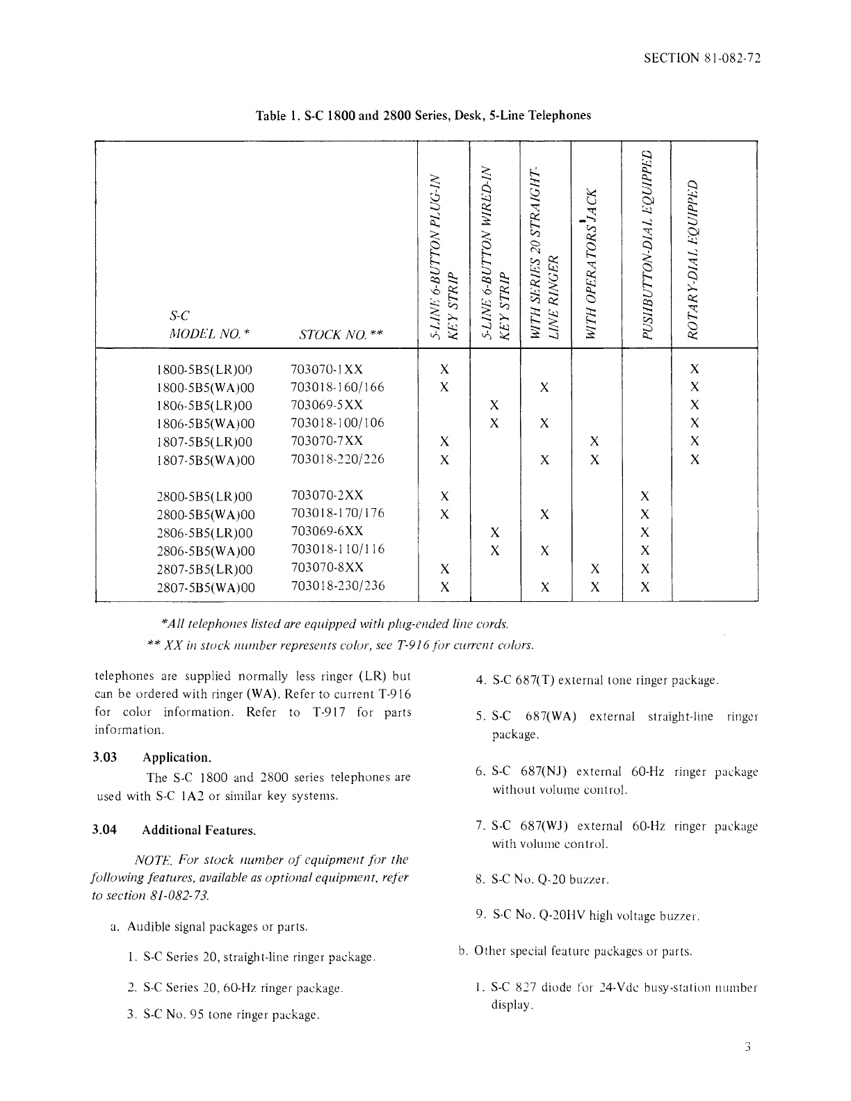
The models, stock numbers, and features
of
the
S-C
1800 and 2800 series, desk, 5-line, rotary-dial and
TONE-DIAL telephones are listed in table
I.
These
TCI Library www.telephonecollectors.info
SECTION 81-082-72
Table
1.
S-C
1800
and
2800 Series, Desk, 5-Line Telephones
~
~
~
E.!.
~
~
::J::
~
~
G
S2
t3
()I
9::
::::i
~
~
_::;
~
:::::
~
=
~
Cl'.)
......i
::::;
< a
Cl'.)
i:t::
::;
@I
~
a
~
Q
f..;.
C'.:t
~
....;:
s h
(".)
el
~
::;
~
::::i
~~
~
~
Q
(!::)
(!::)
~
~<
h
~
'°
~
'°
~
~
;:z
~
::::i
~
~Cl'.)
;§
i:t::
~
Cl'.)
~~
~
~
S-C
;:....
.......
;:....
~
MODEL NO.*
....;:
l.t.;
......i
'.t.l
~~
~
a
STOCK NO.**
Vi
'<
Vi
'<
Q.,.
i:t::
l800-5B5(LR)OO 703070-IXX x x
I800-5B5(W
A)OO
703018-160/166 x x x
I806-5B5(LR)OO 703069-5XX x x
I806-5B5(W
A)OO
703018-100/106 x x x
I807-5B5(LR)OO 703070-7XX x x x
I807-5B5(WA)OO 703018-220/226 x x x x
2800-5B5(LR)OO 703070-2XX x x
2800-5B5(WA)OO 703018-170/176 x x x
2806-5B5(LR)OO 703069-6XX x x
2806-5B5(W
A)OO
703018-110/116 x x x
2807-5B5(LR)OO 703070-8XX x x x
2807-5B5(WA)OO 703018-230/236 x x x x
*All telephones listed
are
equipped with plug-ended line cords.
**XX
in
stock number represents color,
see
T-916 for currellt colors.
telephones are supplied normally less ringer (LR)
but
can be ordered with ringer (WA). Refer to current T-916
for color information. Refer to T-917 for parts
information.
3.03 Application.
The
S-C
1800 and 2800 series telephones are
used with
S-C
1A2
or
similar key systems.
3.04 Additional Features.
NOTE
For stock number
of
equipmellt for the
following features, available
as
optional equipment, refer
to section 81-082-
73.
a.
Audible signal packages or parts.
1.
S-C
Series 20, straight-line ringer package.
2.
S-C
Series 20, 60-Hz ringer package.
3.
S-C
No. 95 tone ringer package.
4.
S-C
687(T) external tone ringer package.
5.
S-C
687(WA) external straight-line ringer
package.
6.
S-C
687(NJ) external 60-Hz ringer package
without volume control.
7.
S-C
687(WJ) external 60-Hz ringer package
with volume control.
8.
S-C
No. Q-20 buzzer.
9.
S-C
No. Q-20HV high voltage buzzer.
b.
Other special feature packages or parts.
1.
S-C
827 diode for 24-Vdc busy-station number
display.
3
TCI Library www.telephonecollectors.info
SECTION 81-082-72
2.
Diode
assembly
package for 18-Vac
busy-station number display.
3. Line cable assembly, SO-foot.
4.
Line cable assembly, 100-foot.
5.
Manual exclusion switch package.
6. Speakerphone package assembly.
7.
Pushbutton
transfer package assembly.
8.
S-C
HRA-SOOA
handset with receiver-amplifier.
9.
Amplifier for use with telephone headset.
4.
INSTALLATION
AND
CONNECTIONS
4.01 Precautions.
When performing work on the
S-C
1800 and
2800 series, desk, 5-line, rotary-dial or TONE-DIAL
telephones, the following precautions should be taken:
4
a.
When removing or replacing housing, first remove
bezel with facemat and faceplate (refer to par.
4.02).
b.
·when
removing or replacing housing, exercise
caution to avoid bending parts or disarranging
wiring.
c.
Spade-tips and skinned wires must make
contact
with their designated terminals only. Electrical
contact
with the metal base,
network
tabs, or
other
components could result in malfunctions in operation
of
telephone, and possible energizing
of
dial
fingerstop with line
or
ringing voltages.
d.
Ensure
that
all
wiring
is
dressed away from ringer
gongs and all moving parts
of
telephone.
e.
Use
electricians scissors or diagonal cutting pliers
to remove insulating tubing used on spare leads
to
avoid breaking leads or pulling spade-tips from leads.
f.
When using a busy station
number
display with
18-Vac power, a diode or diode package assembly
must be installed in each telephone (refer
to
par.
4.06).
4.02
Housing Removal
and
Replacement.
a.
To
remove housing, proceed
as
follows:
I.
Remove bezel, facemat and faceplate by lifting
bezel
out
from top
of
housing, then lift away
from telephone, using an upward motion.
Use
care
in removing the bezel to avoid marring housing.
2.
Loosen two housing screws, located at rear
of
the telephone.
3. Lift housing
out
and down, disengaging housing
dip
from base at
bottom
of
telephone.
b.
To
replace housing, proceed
as
follows:
4.03
I. Hook housing clip into slot located at
bottom
of
the telephone base.
2.
Slide housing in and down over telephone until
housing screws enter slots at rear
of
base.
Tighten screws.
3. Insert bezel
dips
in slots
at
bottom
of
housing,
swing bezel, facemat and faceplate to engage
top
clips on bezel
into
housing slots.
4.
If
bezel does
not
seat properly or
is
loose,
check clips on the bezel and reform
as
necessary.
Telephone Line Connections.
All
S-C
1800 and 2800 series, desk, 5-line,
telephones described in this section are provided with
plug-ended (Amphenol No. 57
or
equivalent) line cords.
Connections are made by inserting the plug into a
house-wired type 66E-3 block or equivalent.
4.04
Ringer and Buzzer Installation.
a.
Mount ringers or buzzers (as required)
as
shown in
the following illustrations.
NOTE.
If
necessary, remove the dial to provide easy
access to ringer and buzzer mountingpoints.
TCI Library www.telephonecollectors.info
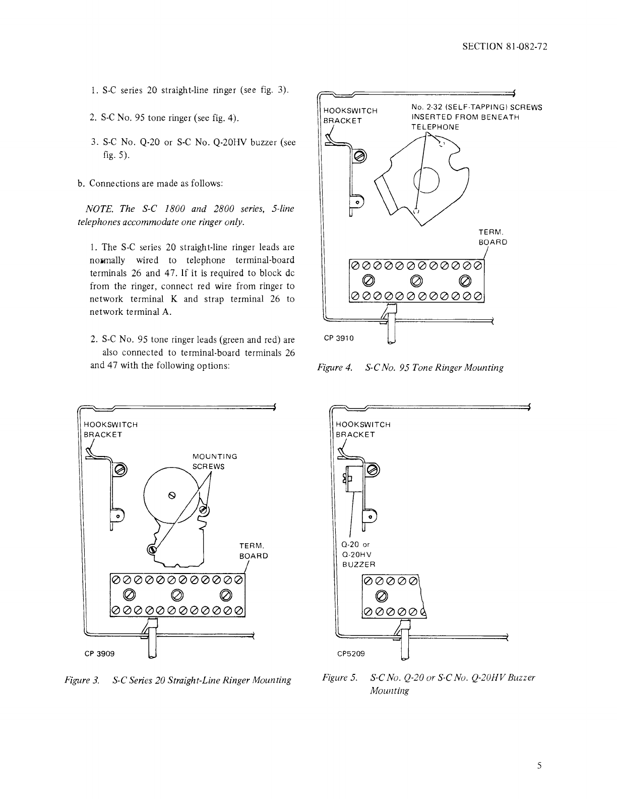
1.
S-C
series 20 straight-line ringer (see
fig.
3).
2.
S-C
No.
95
tone ringer (see
fig.
4).
3.
S-C
No. Q-20 or
S-C
No. Q-20HV buzzer (see
fig.
5).
b. Connections are made
as
follows:
NOTE. The S-C 1800 and 2800
series,
5-line
telephones accommodate one ringer only.
1.
The
S-C
series 20 straight-line ringer leads
are
noiillally wired to telephone terminal-board
terminals 26 and 47.
If
it
is
required to block
de
from the ringer, connect red wire from ringer to
network terminal K and strap terminal 26 to
network terminal
A.
2.
S-C
No. 95 tone ringer leads (green and red)
are
also connected to terminal-board terminals 26
and 47 with the following options:
TERM.
BOARD
000000000000
0 0 0
000000000000
CP
3909
Figure
3.
S-C Series 20 Straight-Line Ringer Mounting
SECTION 81-082-72
No. 2·32 (SELF-TAPPING) SCREWS
INSERTED
FROM
BENEATH
TELEPHONE
TERM.
BOARD
I
r-=0--=0=-0~0--=0=--0-=--=0--=0=--0=-=0--=0=--0:::-;
0 0 0
000000000000
CP
3910
Figure
4.
S-CNo. 95 Tone Ringer Mounting
0
0-20
or
0-20HV
BUZZER
00000
0
00000
CP5209
Figure
5.
S-C No. Q-20 or S-CNo. Q-20HVBuzzer
Mounting
5
TCI Library www.telephonecollectors.info
SECTION 81-082-72
a)
For
ground-connected
ringing or
insulated-generator ringing, remove black
spade-tipped strap
of
tone ringer and replace
resistor with a diode
S-C
827, stock No.
202852-138. Make sure diode
is
insulated
from all metallic parts.
b)
For
battery connected ringing, install
as
received. When loop
is
heavily loaded,
move red lead
of
tone ringer from terminal A
to terminal
B.
If
results are
not
satisfactory,
move red lead back to terminal A and connect
black lead to terminal
B.
c)
To
change the tone
of
the ringer, connect a
0.0047-uF
capacitor, stock No. 202864-
345, between tone ringer terminals M and
N.
NOTE. Most key system power supply
ringing outputs
are
limited to a load
of
two
high-impedance ringers with capacitors, or
eight
high-impedance
ringers
without
capacitors.
S-C
425E-1 NETWORK
CP
16328
NETWORK
-BRACKET
3. Stromberg-Carlson provides the following
buzzers for intercom service:
The
S-C
No. Q-20 buzzer operates from a
source
of
8 to 24 Vac. The
S-C
Q-20HV buzzer
operates at 90 to 105 Vac. Their leads are
normally connected to terminal-board terminals
25 and 48.
If
intercom buzzer
is
to be audible,
when off-hook, move buzzer lead from terminal
25 to 21.
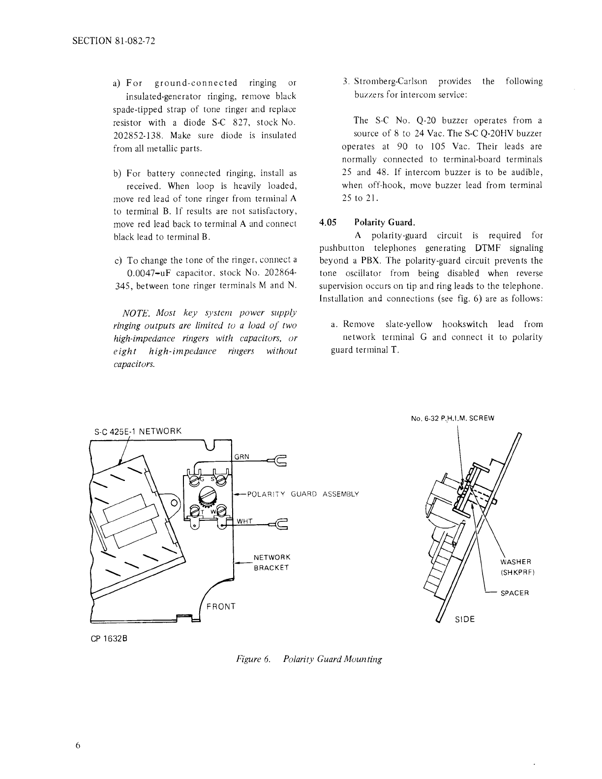
4.05 Polarity Guard.
A polarity-guard circuit
is
required for
pushbutton telephones generating DTMF signaling
beyond a PBX. The polarity-guard circuit prevents the
tone oscillator from being disabled when reverse
supervision occurs on tip and ring leads to the telephone.
Installation and connections (see
fig.
6) are
as
follows:
a.
Remove slate-yellow hookswitch lead from
network terminal G and connect it to polarity
guard terminal T.
No. 6-32 P
..
H.l.M.
SCREW
Figure
6.
Polarity Guard Mounting
6
TCI Library www.telephonecollectors.info

b.
Connect green polarity guard lead to network
terminal
G.
c.
Remove blue key strip lead from network terminal
C and connect to polarity guard terminal S.
d.
Connect white polarity guard lead to network
terminal
C.
4.06 Busy Station Number Display.
To
use the telephone with a busy station
number display (BSND), a diode must
be
connected
in
each telephone
as
described below.
a.
24-Volt Lamps.
When the BSND uses 24-volt lamps and the power
supply
is
24 Vde, make connections
as
follows:
1.
Remove housing (refer .to par. 4.02).
2.
Remove slate-green hookswitch lead from
terminal-board terminal 24 and reconnect it to
terminal
1.
3. Connect cathode (-)
of
an
S-C
827
(INI694)
diode to terminal-board terminal 24. Connect
anode (+) to terminal
1.
4. Connect yellow-brown line cord lead (BL) from
terminal-board terminal 1 (connector pin
number 44) to assigned BL lead
of
BSND.
5.
Replace housing (refer to par. 4.02).
b. 10-Volt Lamps.
When the BSND uses IO-volt lamps and the power
supply
is
18 Vac, diode package assembly
206286-451
is
required. Make connections
as
follows:
1.
Remove housing (refer to par. 4.02).
2.
Connect slate lead
of
diode assembly to
terminal-board terminal I.
3. Connect black lead
of
diode assembly to
terminal-board terminal 24.
SECTION 81-082-72
4. Connect red lead
of
diode assembly
to
network
terminal L2.
5.
Remove red key lead from terminal-board
terminal 24 and reconnect
it
to
network
terminal L2.
6. Tie or tape diode assembly in telephone to
prevent interference with moving parts or
shorting to metal parts.
7.
Connect yellow-brown line cord lead from
terminal-board terminal I (connector pin
number 44) to assigned
BL
lead
of
the BSND.
8.
Replace housing (refer to par. 4.02).
4.07 Line Key
to
Signal Key Conversion.
a.
Remove housing (refer to par. 4.02).
b.
Remove key assembly (refer to par. 5.02).
c.
Remove locking screw from plunger shaft
of
key
position being converted to signaling position.
If
more than one key position
is
to
be
converted to
signaling, the locking screw must
be
removed for each
position converted.
d. Make connections
as
shown in table
2.
e.
If
more than one key position
is
required for
signaling, multiple the position leads on terminal
52.
NOTE. Store the key locking screw 011 telephone
base
using adhesive
tape.
Tlzis
screw
is
special and
would be necessary to restore key to
nomwl
line
use.
f.
Replace key assembly (refer to par. 5.02).
g.
Replace housing (refer to par. 4.02).
7
TCI Library www.telephonecollectors.info

SECTION 81-082-72
Table 2. Line Key to Signal Key Conversion
Wiring
KEY
POSITION CONDUCTOR
CONVERTED COLOR
1 White
2 Orange
3 Brown
4 Green
5 Slate
4.08 All Buttons Released Intercom.
To provide all-buttons-released intercom
on
S-C
No. 1A2, W.E.
lAl,
or
other
1A2 systems, proceed
as
follows:
a.
Remove housing (refer
to
par. 4.02).
b. Connect T, R, A, L, and
LG
to dial or manual
intercom circuit (see fig. F0-1 to
F0-3,
as
required).
c.
Insulate and store slate-yellow, yellow-slate, and
yellow-brown leads.
d. Replace housing (refer
to
par. 4.02).
-MOUNTING
SCREW
HOOKSWITCH
OFF·HOOK
AND
EXCLUSION SWITCH OPERATED
OPEN
CLOSED
OPEN
MOVi?
FROM
TO
TERMINAL TERMINAL
51
52
51
52
50 52
49
52
49 52
4.09 Manual Exclusion Switch Installation.
NOTE. For multiline exclusion, refer to section
66-128-80.
a. Remove housing (refer
to
par. 4.02).
b. To
mount
manual exclusion switch, proceed
as
follows:
1.
Assemble exclusion switch to base
u~ing
two
mounting screws provided. Do
not
tighten
screws securely (see fig. 7).
HOOKSWITCH HOOK
\EXCLUSION:WITCHB~OSED
\
OPEN
-'\.llllliP~
CLOSED
HOOKSWITCH ON-HOOK
AND
EXCLUSION SWITCH NOT OPERATED
NOTE:
Connect exclusion switch
leads
as
shown in Figure F0-1
CP
1858A
EXCLUSION SWITCH
MOUNTING
POSITION
Figure
7.
Manual Exclusion Switch Mounting and Operation
8
TCI Library www.telephonecollectors.info
2.
Adjust exclusion switch
position
so
that
hookswitch
assembly rests against its
stop
before exclusion switch
operating
pin
stops
against
exclusion switch base.
3. Tighten
mounting
screws.
4. With
handset
off-hook
and
exclusion switch
operating
pin pulled
out,
sleeve
attached
to
the
operating
pin
should
move
between
pile-up springs
sufficiently
to
open
and
close
contacts.
5.
When the
handset
is replaced
on-hook,
the
end
of
the
hookswitch
assembly should move the
sleeve between the pile-up springs
and
operate
the
contacts.
6.
If
the exclusion switch does
not
operate
as
described in steps 4
and
5 above, loosen the
mounting
screws, realign
the
exclusion switch,
and
retighten the screws.
c. Exclusion switch
connections.
1.
Any
one
of
the five lines can be wired for
manual exclusion.
2.
Connect
leads
from
exclusion switch,
as
shown
in table
3.
3.
Connect
excluded
station
wires
of
line cord
as
shown in wiring diagram (see fig.
F0-1
to
F0-3).
d. Check
operation
of
exclusion switch for
affected
line.
SECTION 81-082-72
e. Replace housing
(refer
to
par. 4.02).
4.10
Pushbutton
Transfer.
a.
Order
transfer
pushbutton
package assembly.
b. Remove housing
(refer
to
par.
4.02).
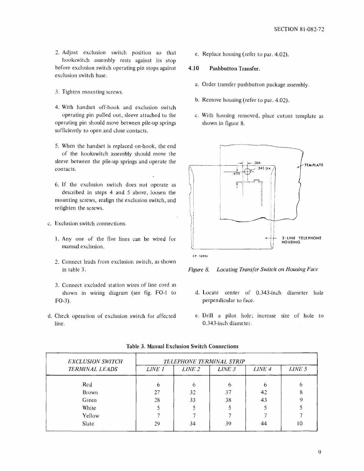
c. With housing removed, place
cutout
template
as
shown in figure 8.
G-----1
.i.
·~
....
)II
I rr·1
TEMPLATE
I I
ii
I I
\ I
J'
1 I
'I
I
I I
I;
I I
5·LINE
TELEPHONE
HOUSING
CP
l695A
Figure
8.
Locating Transfer Switch on Housing Face
d. Locate
center
of
0.343-inch
diameter hole
perpendicular
to
face.
e. Drill a pilot
hole;
increase size
of
hole
to
0.343-inch diameter.
Table 3. Manual Exclusion
Switch
Connections
EXCLUS/ON SWITCH TELEPHONE TERMINAL
STRIP
TERMINAL
Lt.ADS
LINE
I
LINE
2
LINE3 LINE4 LINES
Red 6 6 6 6 6
Brown
27
32 37
42
8
Green
28
33
38
43 9
White 5 5 5 5 5
Yellow 7 7 7 7 7
Slate
29
34
39
44
10
9
TCI Library www.telephonecollectors.info

SECTION 81-082-72
f. Mount switch assembly to network bracket with
two screws provided (see fig. 9).
NETWORK
00
00
MTG
BRACKET
00
0
00
NETWORK
~
0
CP
2957
0
Figure
9.
Transfer Switch Assembly Mounting
g.
Connect black lead
of
switch assembly to network
terminal L
1.
h. Connect yellow lead
of
switch assembly
to
network terminal L2.
i. Connect one end
of
spare line cord conductor to
network terminal L2. Connect other end
of
spare
line cord conductor to earth ground.
j.
Replace housing (refer
to
par. 4.02).
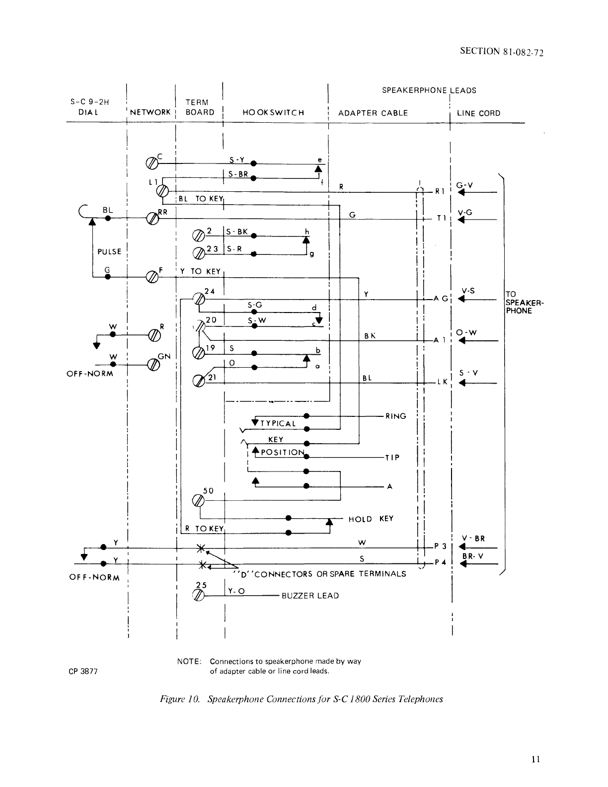
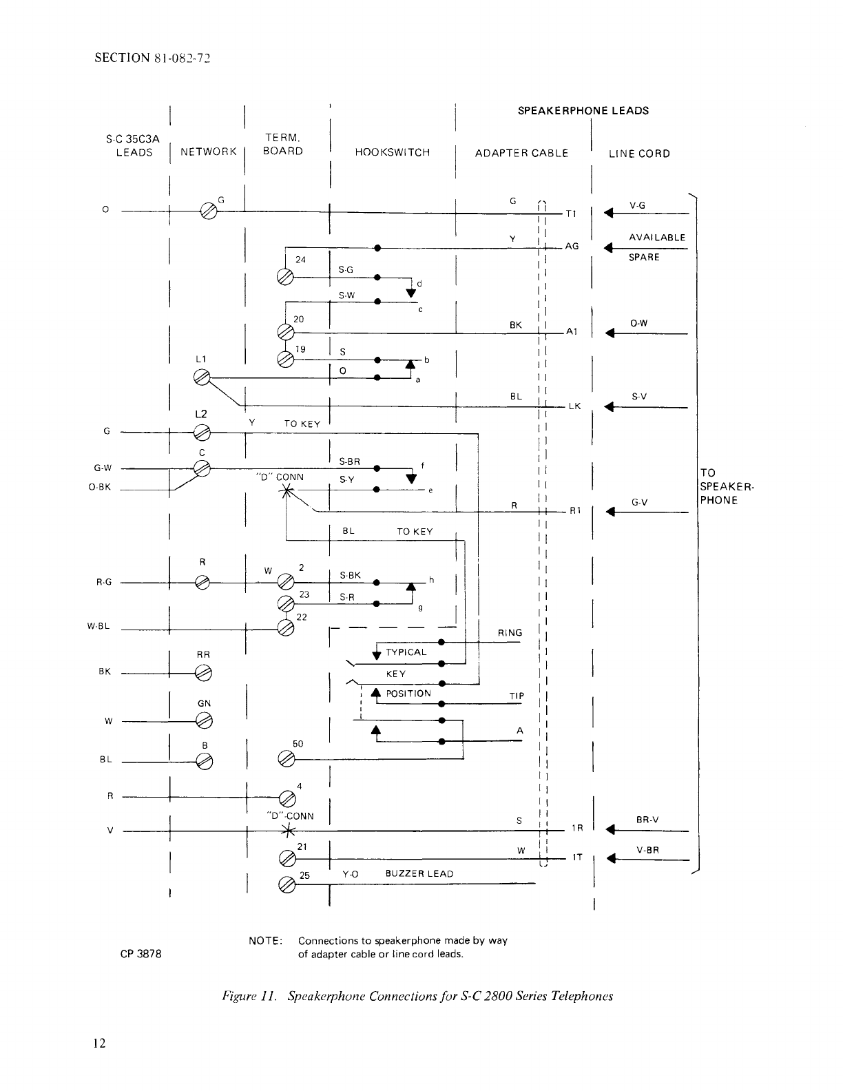
4.11 Speakerphone Connections.
The
S-C
1800 and 2800 series, desk, 5-line
telephones can
be
used with a W.E.-type speakerphone.
It
is
necessary to add an appropriate dial and provide
connections to the speakerphone by way
of
an adapter
cable or spare telephone line cord leads. However, if
telephone line cord leads
are
used for this application,
the all-buttons-released intercom feature cannot be used.
To make connections, proceed
as
follows:
a.
Remove housing {refer to par. 4.02).
b. Remove dial (refer to par. 5.04).
c.
Replace with appropriate dial.
10
d. Connect dial leads
as
indicated in table 4 or 5
and figure 10 or
11.
e.
Connect telephone to speakerphone
as
indicated in
table 6 or 7 and figure 10 or 11.
f. Replace housing (refer to par. 4.02).
Table 4.
S-C
1800 Series Telephone
Connections for
W.E.
Speakerphone
DIAL CONNECT
TO
LEAD TERMINAL
Blue Network
RR
Green Network F
White Network R
White Network
GN
Yellow *
Yellow *
*Use D connector or spare terminal.
Table
5.
S-C
2800 Series Telephone
Connections for W.E. Speakerphone
DIAL CONNECT TO
LEAD TERMINAL
Green Network L2
Black Network
RR
Orange Network G
Red-Green Network R
White Network
GN
Green-White Network C
Orange-Black Network C
Blue Network B
White-Blue Term. Bd. 22
Red Term. Bd. 4
*Violet Slate Lead
{Adapter Cable)
or
Brown-Violet Lead
(Line Cord)
*Use D connector or spare terminal.
TCI Library www.telephonecollectors.info
S-C
9-2H
DIAL
I
I NETWORK I
I I
BL
PULSE
G F
r-
_,w-~-1t7l\R
~
•
'lU
.':,___,1---(/)GN
OFF-NORM
y
CP
3877
SECTION 81-082-72
TERM
BOARD
SPEAKERPHONE LEADS
I
HOOK
SWITCH
TO
KEY
@2
15-BK
@23
S-R
:
d
b
C I
I
ADAPTER CABLE
R
G
y
BI\
'
,
...
:I
I I
I I
I
I I
11
I:
I
I I
I;
' LINE
CORD
I
I
I
I
G-V
Rl '•
IV-G
Tl
•
v-s
AG
•
o-w
Al
•
s-v
V/J'~-t----------;--;---r-B_L
____
t-+-LK
••i--~-
.---------+--+---RING
TYPICAL
KEY
I
+POSITIO~
I
TIP
50
~----w----+---~A
''D'
'CONNECTORS
OR
SPARE
TERMINALS
25
I
r7J..
Y-
0
'ILJ'--~--~---BUZZER
LEAD
NOTE: Connections
to
speakerphone made
by
way
of
adapter cable
or
line cord leads.
TO
SPEAKER-
PHONE
Figure 10. Speakerphone Connections for S-C 1800Series Telephones
11
TCI Library www.telephonecollectors.info
SECTION 81-082-72
S-C
35C3A
LEADS NETWORK I
0
e/
I
I
I
L2
G
c
1/0
G-W
0-BK
I
R
R-G
W-BL
RR
BK
0
GN
w 0
B
BL
0
R
v
CP
3878
SPEAKERPHONE LEADS
TERM.
BOARD I HOOKSWITCH ADAPTER CAB
LE
I
I G
y
~24
I
S-G
•
~d
S-W
20 BK
19 s b
0
BL
y
TO
KEY
IS-BR • f
"D"
CONN S-Y •
t I • R
I
BL
TO
KEY
I1
2
w S-BK h I
23
S-R
22 I
1--
RING
TYPICAL
'
KEY
,,,....
•
I
'POSITION
•
:
' I
50
0
4
0
"D"-CONN
*
021
025
Y-0
BUZZER
LEAD
NOTE: Connections
to
speakerphone
made
by way
of
adapter cable
or
line cord
leads.
TIP
A
s
w
"
I I
Tl
I I
I 1
I AG
I I
I
1 I
1 I
11
1 I
I
Al
I
1 I
I I
11
11
I
LK
11
11
11
1 I
11
11
11
Rl
lR
I
, 1
LJ
1T
I LINE CORD
I V-G
I
...
AVAILABLE
•
I SPARE
I
0-W
...
I S-V
I
...
G-V
...
BR-V
...
...
V-BR
Figure 11. Speakerphone Connections for S-C 2800 Series Telephones
12
TO
SPEAKER-
PHONE
TCI Library www.telephonecollectors.info

SECTION 81-082-72
Table 6. Speakerphone and Telephone Connections for
S-C
1800 Series Telephones
REMOVEFROM CONNECT
TO
LEAD DESIGNATION
AND
COLOR TERMINAL TERMINAL
Key Yellow Network
LI
Network F
Key Blue Network c Network
LI
Hookswitch Slate Term. Bd.
25
Term. Bd. 19
Buzzer Yellow-Orange Term. Bd.
21
Term. Bd.
25
Hookswitch Slate-Yellow Network F Network c
Adapter Cable:
RI
Red Network
LI
Tl
Green Network RR
AG
Yellow Term. Bd. 24
Al
Black Term. Bd. 20
LK Blue Term. Bd.
21
P3 White Dial off-normal yellow lead*
P4 Slate Dial off-normal yellow lead*
Line Cord:
Rl
Green-Violet Network
LI
Tl
Violet-Green Network RR
AG
(Use Spare Lead) Term. Bd. 24
Al
Orange-White Term. Bd. 20
LK
Slate-Violet Term. Bd.
21
P3 Violet-Brown Dial off-normal yellow lead*
P4 Brown-Violet Dial off-normal yellow lead*
*Use D connector.
13
TCI Library www.telephonecollectors.info

SECTION 81-082-72
Table 7. Speakerphone and Telephone Connections for
S-C
2800
Series Telephones
14
LEAD
DESIGNATION
AND
COLOR
Hookswitch Slate-Yellow
Key Blue
Key Yellow
Hookswitch Slate-Brown
Hookswitch Slate
Hookswitch Orange
Buzzer Yellow-0range
Terminal Board:
Term. No. 2 White (Strap)
Adapter Cable:
Rl
Red
Tl
Orange
AG
Yellow
Al
Black
LK Blue
IT
White
IR
Slate
-Brown
Line Cord:
Rl
Green-Violet
Tl
Violet-Green
AG
**Spare
Al
0 range-White
LK
Slate-Violet
IT
Violet-Brown
IR
Brown-Violet
*Use D connector.
**Use available spare.
REMOVE FROM CONNECT
TO
TERMINAL TERMINAL
Network G *Key Blue
Network c *Hookswitch Slate-Yellow
Network
L1
Network L2
Network
L1
Network c
Term. Bd. 25 Term. Bd. 19
Term. Bd. 25 Network
L1
Term. Bd.
21
Term. Bd.
25
Network
GN
Network R
*Key and Blue
*Hookswitch Slate-Yellow
Network G
Term. Bd. 24
Term. Bd. 20
Network
L1
Term. Bd.
21
*Dial Violet
Insulate and Store
*Key Blue
*Hookswitch Slate-Yellow
Network G
Term. Bd. 24
Term. Bd. 20
Network
L1
Term. Bd.
21
*Dial Violet-0range
TCI Library www.telephonecollectors.info
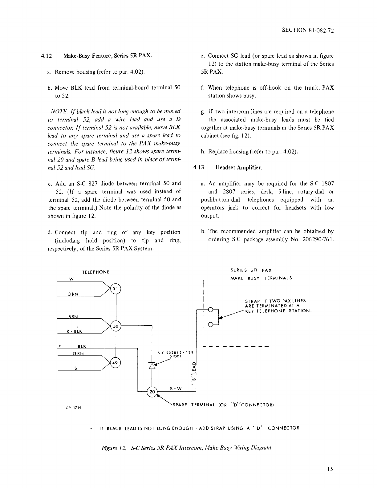
4.12 Make-Busy Feature, Series SR PAX.
a.
Remove housing (refer to par. 4.02).
b.
Move
BLK
lead from terminal-board terminal 50
to 52.
NOTE.
If
black lead
is
not
long enough to be moved
to terminal 52, add a wire lead and use a D
connector.
If
terminal
52
is
not
available, move
BLK
lead to any spare terminal and use a spare lead to
connect the spare terminal to the
PAX
make-busy
terminals. For instance, figure
12
shows spare termi-
nal
20
and spare B lead being used
in
place
of
termi-
nal
52
and lead
SG.
c.
Add an
S-C
827 diode between terminal 50 and
52.
(If
a spare terminal
was
used instead
of
terminal 52, add the diode between terminal
SO
and
the spare terminal.) Note the polarity
of
the diode
as
shown
in
figure 12.
d.
Connect tip and ring
of
any key position
(including hold position) to tip and ring,
respectively,
of
the Series SR PAX System.
TELEPHONE
w
R- K
SECTION 81-082-72
e. Connect
SG
lead (or spare lead
as
shown
in
figure
12) to the station make-busy terminal
of
the Series
SR
PAX.
f. When telephone
is
off-hook on the trunk, PAX
station shows busy.
g.
If
two intercom lines are required on a telephone
the associated make-busy leads must
be
tied
together at make-busy terminals in the Series
SR
PAX
cabinet (see
fig.
12).
h. Replace housing (refer
to
par. 4.02).
4.13 Headset Amplifier.
0
<
w
.....
a.
An amplifier may
be
required for the
S-C
1807
and 2807 series, desk, S-line, rotary-dial or
pushbutton-dial telephones equipped with an
operators jack to correct for headsets with low
output.
b.
The recommended amplifier can
be
obtained by
ordering
S-C
package assembly No. 206290-761.
I
I
L_
SERIES 5 R
PAX
MAKE
BUSY
TERMINALS
STRAP
IF
TWO
PAX
LINES
ARE
TERMINATED
AT
A
KEY
TELEPHONE
STATION.
CP
1714 SPARE
TERMINAL
(OR
''D'
'CONNECTOR)
*
IF
BLACK LEAD IS
NOT
LONG
ENOUGH
-ADD
STRAP
USING
A
''D''
CONNECTOR
Figure
12.
S-C Series 5R
PAX
Intercom, Make-Busy
Wiring
Diagram
lS
TCI Library www.telephonecollectors.info
SECTION 81-082-72
5.
Connections are indicated in figures F0-2
or
F0-3
(and
package assembly instructions).
c.
The amplifier
is
stored in the telephone housing
away from moving parts
of
telephone.
MAINTENANCE
NOTE. For S-C stock number
of
components
required to maintain telephone instrument, refer to
T-917.
5.01
Network
Assembly Replacement.
a. Remove housing (refer to par. 4.02).
b. Disconnect all leads on old
network
assembly.
c.
Remove two
network
mounting
screws located
at
upper left and lower right
of
network
assembly.
d. Remove old
network
and replace with new one
and secure the
network
bracket.
e. Connect telephone leads as shown
in
figure F0-1.
f.
Replace housing (refer to par. 4.02).
5.02 Line
and
Hold Key Assembly Replacement.
16
a.
Remove housing (refer
to
par. 4.02).
b.
Loosen two screws holding key assembly to key
mounting bracket.
c. Disconnect the key assembly from
connector
plug.
d. Lift key assembly forward and up removing it
from bracket assembly.
e. Place new key in position, reconnect
connector
plug, and tighten two captive screws holding the
key assembly to mounting bracket.
f.
Replace housing (refer to par. 4.02).
g.
Test each key to ensure
that
any depressed key
restores when another line key
(or
hold
key)
is
depressed.
5.03 Hookswitch Replacement and Adjustment.
a.
Replacement.
1.
Order hookswitch assembly.
2.
Remove housing (refer to par. 4.02).
3. Disconnect hookswitch leads at terminal board
and
network
assembly.
4. Remove hookswitch mounting screws. Remove
top
screws. Remove top screw first and slide
network
bracket back to expose
bottom
mounting
screws.
5. Remove
hook
and hookswitch assembly.
6.
Turn
assembly upside down and
hold
in an
operated position.
7.
Lift spring pusher
out.
Care must
be
taken so as
not
to damage
contact
springs.
8. Remove
hook
tension spring and shaft, and
remove handset cradle
hook.
9. Connect leads from new
hookswitch
to
network
and terminal board terminals (see fig.
F0-1 to F0-3 as appropriate).
10. Assemble hookswitch assembly and
handset
cradle
hook
by reversing process
of
step 8.
11.
Operate hookswitch assembly and insert spring
pusher.
12. Mount complete assembly
to
base
with
the
three screws removed in step 4.
13.
Replace housing (refer to par. 4.02).
b. Hookswitch Tension Spring Adjustment.
1.
Remove housing (refer
to
par. 4.02).
2.
Remove handset from
hook.
Hook should move
to off-hook position.
If
not,
increase tension
on-hook
by
reforming upper spring tab.
TCI Library www.telephonecollectors.info
3. Place handset on-hook to ascertain that
hookswitch restores fully.
4.
Replace housing (refer to par. 4.02).
c.
Contact Spring Adjustment.
5.04
l.
Remove housing (refer to par. 4.02).
2.
Check operation
of
contact springs. Contact
should have a slight follow in operation.
Contacts on the lower and upper spring
of
a
combination must engage simultaneously.
3.
If
necessary, reform contact springs with
standard relay adjusting tool
so
that c-d
contacts make first, e-f contacts make second, and
g-h
contacts break last. Refer to figures F0-1 to
F0-3
as
appropriate.
4. Replace housing (refer to par. 4.02).
Dial
Replacement.
NOTE. For repair and replacement parts
of
S-C
35-type pushbutton dials refer to section 89-922-
70.
For
repair and replacement parts
of
S-C rotary-dials refer to
section 89-925-
70.
a.
Remove housing (refer to par. 4.02).
b.
Loosen wing screw on right side
of
dial and slotted
screw on left side
of
dial.
c.
Disconnect dial leads from network and terminal
board.
d. Replace with new dial and connect leads to
network
as
shown in figures F0-1 to F0-3
as
appropriate.
e. Replace housing (refer to par. 4.02).
5.05 Line Lamp Replacement.
a.
Remove bezel (refer to par. 4.02).
SECTION 81-082-72
b.
Remove plastic retaining collar around key
buttons.
c. Remove key designation cap.
d.
Remove key lamp cover.
e.
Carefully remove lamp with lamp extractor
(S-C
stock No. 896264 or equivalent).
f.
Clean metal contact surface
of
new lamp and
check spring tension and alignment
of
lamp
contact springs.
g.
Insert new lamp with
glass
end towards key
button.
h. Replace items removed in steps a through d in
reverse order.
5.06 Handset Replacement.
NOTE. For handset repair and replacement parts
refer to section 89-903-
70.
a.
Order handset in applicable color.
b.
Remove housing (refer
to
par. 4.02).
c. Remove dial (refer to par. 5.04).
d. Remove terminal-board mounting screws; make
certain
that
terminal-board spacers and
lockwashers are not lost.
e. Disconnect handset cord leads from terminals
2,
3,
22, and 23.
f.
Replace with new handset assembly or handset
cord, and reconnect leads to terminals
2,
3, 22,
and 23. (See figure F0-1 to
F0-3
as
appropriate.)
g.
Reposition top terminal board, secure with screws,
spacers, and lockwashers removed
in
step
d.
h. Replace housing (refer to par. 4.02).
17/18
TCI Library www.telephonecollectors.info

TCI Library www.telephonecollectors.info

*
INCLUDES
1800-5B5
1806-5B5
2800-5B5
2806-5B5
1810-5B5
1816-5B5
2810-5B5
2816-5B5
1810-5L5
1816-5L5
2810-5L5
2816-5L5
NOTES:
1.
WHEN
A
COMMON
SIGNAL
IS
REQUIRED
USING
STANDARD
RINGING
VOLTAGE,
THE
FOLLOWING
OPTIONS
ARE
AVAILABLE:
)
~.
3.
4.
5.
A.
s
..
c
SERI
ES
20
STRAIGHT-LINE
RINGER.
ORDER
PACKAGE
ASSEMBLY
702100-244,
AND
WI
RE
AS
SHOWN.
EXCEPTION
-
WHEN
CAPACITOR
IS
REQUIRED
TO
BLOCK
DC
FROM
RINGER,
CONNECT
RED
RINGER
NI
RE
TO
NETWORK
TERMINAL
K
AND
STRAP
TERMINAL
26
TO
NETWORK
TERMINAL
A.
B.
3-C
SERI
ES
20
RINGER
FOR
60
HZ.
ORDER
PACKAGE
ASSEMBLY
702100-260.
CONNECT
BLK
WI
RE
TO
TERMINAL
47
AND
RED
WI
RE
TO
TERMINAL
26.
DO
NOT
WIRE
IN
CAPACITOR
A-K.
C.
TONE
RINGER.
ORDER
PACKAGE
ASSEMBLY
202100-488
AND
WI
RE
PER
INSTR
UC
TION
SHEET
IN
PACKAGE
USING
TERMINALS
26
AND
47.
WHEN
8-24
VAC
BUZZER
IS
REQUIRED,
ORDER
S-C
Q-20
BUZZER
(S-C
703504··023)
AND
MOUNT
PER
INSTRUCTION
SHEET
ENCLOSED.
FOR
INTERCOM
SIGNAL
TO
BE
AUDIBLE
WHEN
OFF
HOOK,
CONNECT
.31
GNAL
LEAD
TO
TERMINAL-BOARD
TERMINAL
21
INSTEAD
OF
25.
WHEN
TELEPHONE
IS
USED
WITH
BUSY
STATION
NUMBER
DISPLAY
(24-VOLT
LAMPSA
MOVE
THE
SLT-WHT
HOOKSWITCH
WI
RE
FROM
TERMINAL-BOARD
TERMINAL
24
TO
1
AND ADD
AN
S-C
827
DIODE
(202852-138)
AS
SHOVvN.
WHEN
10-VCLT
LAMPS
(AND
18-
VAC
POWER)
ARE
USED,
ORDER
DI
ODE
PACKAGE
ASSEMBLY
206286- 451
AND
CHANGE
WIRING
PER
INSTRUCTION
SHEET
IN
PACKAGE
AS3EMBLY.
"B"
LEADS
MAY
BY
USED
AS
SPARES
OR
MULTI
PLED
TOGETHER
AS
A 1
LEADS
ON
TERMINAL-
BOARD
TERMINALS
19
AND
20.
6.
TO
CONVERT
LI
NE
KEY
FROM
"Pl
CKUP"
TO
"SIGNAL"
FUNCTION,
REMOVE
PLUNGER
LOCKING
SCREW
TO
MAKE
KEY
NON
LOCKING,
AND
MOVE
THE
FOLLOWING
WIRE:
A.
POSITION
1 -
WHT
FROM
TERMINAL-BOARD
TERMINAL
51
TO
52.
B.
POSITION
2 -
ORN
FROM
TERMINAL-BOARD
TERMINAL
51
TO
52.
C.
POSITION
3 -
BRN
FROM
TERMINAL-BOARD
TERMINAL
50
TO
52.
D.
POSITION
4 -
GRN
FROM
TERMINAL-BOARD
TERMINAL
49
TO
52.
E.
POSITION
5 -
SLT
FROM
TERMINAL-BOARD
TERMINAL
49
TO
52.
7.
TO
PROVIDE
"ALL
BUTTONS
RELEASED
INTERCOM",
CONNECT
CHAI
NI
NG
SWITCH
T,
R,
LG
AND
L
LEADS
TO
INTERCOM
CIRCUIT
AS
SHOWN.
8.
9.
TO
PROVIDE
MANUAL
EXCLUSION
(DESK
MODELS
ONLY).
ORDER
PACKAGE
ASSEMBLY
206289-781
AND
WIRE
AS
SHOWN.
(EXAMPLE:
LINE
1:
CONNECT
EXCLUSION
SWITCH
BRN,
GRN,
3LT
LEADS
TO
TERMINAL··BOARD
TERMINALS
27, 28,
29
RESPECTIVELY
AND
LI
NE
CORD
EXCLUSION
R,
T,
A
LEADS
TO
EXCLUDED
STATI
ON(.3)
LI
NE
1).
WHEN
POLARITY
GUARD
IS
REQUIRED
FOR
TONE-DIAL@SIGNALING
UNDER
REVERSED
BATTERY
CONDITIONS,
ORDER
PACKAGE
ASSEMBLY
703016-852
AND
WI
RE
PER
INSTRUC·
TION
SHEET
IN
PACKAGE
ASSEMBLY.
703504-051
Sheet
1
Is~,
S-C
9-2C
DIAL
PULSE
BL
5-C
180011810
S:?:RIES
5-LINE
TELEPHONES
•
------
S-C
425E-1
NETWORK
I
I
I
I:
I
HANDSET
'r------r--_l_
___
_
TERMINAL
I HOOKSWITCH
BOARDS I
ION
HOOK l
--,
---
1
I
S-Y
I
MAKES
ls-BRSECci~
-
------.-=--
f
I
SECTION 81-082-72
SIGNALS
r------<~w--t---t-~cGN•l----+----L-------'--~w'---,
I
I
I
OFF
NORMAL
w I I
,----:~-~;-
-
-h-
-,-
---------
S-81<
1 BREAKS I
'----<It---:--~"
Is-•
LAST
g I
.
___
l ________
_I_
·~
~
---
~-~
---
___
/
I I
I I
~--------~---t----------~
22
I I R '
r----~~~-
I I BK
' I
STRAP
.
{NOTE
IA)
'----l
_____R
____
l_
--
_T~~~S~~~~R--
-*
1
I RINGER
I (
NO;E
I)
N~E
~-~---~----'-.
I
S-G
.MAKES,..
d
~
IS-W
FIRST
~
--:---:
--~c~------,
21>--~'---~---
I
I a
25>J::----:l_s
---\:-
I NOTE ' b
I
I
I
48
BUZZER
NOTE
2
1--
___
_.l
___
-
I
EXCLUSION
I~
I
(NOTE
8 l
©:-=-~---.----'--,
,--=::.=..:.}
s : *
Y-0
0-Y
WALL
MODEL
ONLY
SEE
PAGE
3
@o•@o•®r
o•@o•@ f
~---~
I
I
I
V-BL
V-0
Figure F0-1. S-C5-Line Telephone, Wiring Diagram (Sheet 1
of
2)
19/20
TCI Library www.telephonecollectors.info
S-C
35A3
A
DIAL
10
BK
17
R-G
w
W-BL
S-C
2800
/2810
SERIES
5-LINE
TELE
PHONES •
S-C
425E-
I NETWORK HANDSET TERMINAL I HOOKSWITCH
BOARDS I (ON
HOOK)
w
I
ls-Y
J
MAKES
ls-BRSECONO
e
I
,---1;_;;---h--1-
1
BREAKS
I
SIGNALS
-----'-----}~·
S-BK
------""'
BREAKS
W
LAST
R~CEIVER
~
_
_s.:.~-
___
_,.
.___._,___,,__--{:23
Is-•
LAST
g I
,
___
)_
________I
__
-
•2
I I
I I
---t--"---;--+------1---+-----~----..-~----,---
--·-
----f-
-
• I
WALL
MODEL
ONLY
IT--------'-"'----r-'
I I
---+---"---i---+------1----'--=-------'---I
I
' I R I
0-BK
TRAP
(NOTE
IA)
703504-051
Sheet
2 Issue 2
BK
-----------r--,__~~~~~~___,
I NOTE
I •
I
I
I
I
I
I
I
I
I
26
I
.t
I
~
I
~•-•
I
l~dl
20
: s-w FIRST c I
I
I
Io
I
I a
2s;r---;-
1
•~_._---',._
I
NOTE
3 b
4B
BUZZER
NOTE
2
L----,---
- -
:
E~;~TUC~ON
I
I
@)0•@0•§1
oR@oRE)
I
I
I
I
(NOTE
81
I
IR
I
BR
._
____
Y:_·.:-_O_
~!€E
0-Y
3
Bl-V
'----~~--~
V-0
CONT'D
FROM
PRECEDING
PAGES
CONT'D
FROM
PRECEDING
PAGES
SECTION 81-082-72
KEV 8 CONNECTOR
TE~EPHONE
COfHECTOR
TERMtNAL
BOARDS CONNECTOR
NO.
I
TEL
LtNE
CORD
lw
®
( :
~
i
:::
~51
----''--------------------'-----,
I
IR-8K
I I
IG
___
_
I I
~
T49
I I
.r----ee------<<
I I 1
-E-l--if---+--+--+-+-+-f--f--f--'-
1
---{21•>--'--"'"L~-~w~
R
KE
y~
=,-:
..
=====:::=:=---<
::
:
::
=--------+--+-+-t-1-1---+-l-;
2
B"---------'---'W=-B,_,L_
26
T
__._'----+--+-+---<
2 I 2
-----~~
I
POS
I • I
W-0
A,H,S
-
.,,___
___
-+-+---<
27
I 2
7-E----+---+-+-+-f-f--f--'-
1
------{~
G _ W
27
(~RlSI
LAMP
{~P,~~
!==========~=~======~
13 I
l3
--------+-+-+-<----<---+-I'--<~
W - G
'-.....
-38J38
I
31
28
LG
:
·~----+---+----<
28:
2B
-! :
33
W-BR
29
T
~·-----+-+-----<
4 I 4
~-
: @-
_N_9!_E_51~
5 B
·""--------e---+--+----<-...
29129
--------+--I-I---+-'----{~
I
BL-
R
30
(~
1
:i'~1
KEY
POS 2
,.
- 3 I 3
-----+-t----+-+-+--+----'---{:
32>>---~•BR-~w
4 R ]
,-:::i---------+-+----<
14 I 14 !
3'5
I R
-BL
6 L
LAMP
r~ro~~·+-1-----e-+-+----<
39,39-----L---+-+-l--l---+----'-----{3~6--'--:-"----''-"----~
31
LG
KEY
:
:.._
__
_..
--,___+'+----<
3:
:
3:------+---+-+-t-r-+----\3771--38--~i
~R--0-~
'"
RB
I I
o-R
]
POS
3
--'
0
------4-Hl--1-------<
6 6
~-
~9,L
__
o.!._E~
I~
...
I I
q-G
A,H,S
..__--~-+--+-----<
31
31
E-----
40
~
I
BR-R
33
'Lo=ns1
/.~;::i..·-----<----+-+-------<1sl
1s----------t-1----<---+~-\'
LAMP
(~:
(o_+-1
___
___,
____
--1-+-------<
40
I
40
---------H--1-+----'-----{•4
,,
\---'--~
-"""-'-
•
.,.,____,..
34
LG
_ I I
s-•
KEY
-:-----------~_----..--'
I
'O
7
11
7
___,__---+-+-+---+--'---{42!~I
•O
R J
I
..
--@
:
R-S
__,:_~~====~-:=~~~======~
382:
382
~
--;191-~~qrE_51
BL-
BK~
35
: S
POS
4
•""------..+-+-----<
33 33
~---
-----+--1-----+---''--'-~_,44
I
BK-
BL
3,
26
~L·::s1
/.~M---------+-+-----<
16116
~-
-----+---+--+--;~
I
0-BK
LAMP
(\[~':!----
...
+-+-----<~
41
1
4
i•-~---------+-+--+-'-------<46''---'--:~·-'-K-__,O'---
37
~G
I :
G-
BK
KEY
-
,:'----~
:~=====~:=t~=t======~-:4:
,:
_
-~---+-+---1--\1:9,'--~---0-!_E-~---'!---':-:-~-BGK___,,,
;;
: J
POSS
-
10110
I
• - ,
<E--------+-1---~39
A,>-1,S
-
L-------e---+--+----<,
~:I~:
I
t1"7'
:;~;
is
tcR1s1
LAMP
(fol
42
I
42
---------Hr---------'-------{02•'--'---='-'----'--
40
L.G
~~---+-+---<24
124
-I
+4
"--------
-+-+-----<25
I
25
------+-----~
I
I ,8
,_
__
__,___,o~-~v~,..
22
KEY
~----~-+--+----<23123-"----+-+------t---r-----<I
HOLO
8 I I
INTERCOM
I I
LINE
I
LINE
2
LINE
3
L.1
NE
4
LINE
5
/.7''1----------<1>----l-f----<1a
I
is------+-----1--t--~
1
~
1e
L
LAMP(~
-
i43l43....-..
: 0
Y-G
>i43
L.G
I I
BL-Y
CHAINING
SWITCH
.~----<-HH------<i2ol
20~
~1------
+--~
1
----{'31\--='----'-----
•6
•
:
.~----4-H--1------<
45:
45
-----+--------1-----i:C--e
:y -
BL
JI
4 1
:
r-----·------<(
2
ii
2 I : : V _ S
~1-~•--------•.----------<'46146----i-----------'----{05i\--'--
1
"-----''---•
50
A l
"'"""
J
-_______
5
YYL:_:_!~B!!jc____
1
1
1
1
~-·j----------
---c',c-------~:--':-~S,--'-3'
:~
::~::::
--
------'-----'-'---'-
8
'-'R~
44
BL(OR)
LS
RED I
o-w :
---~~--------'--'--------'----'o._-_w_.,...
2
________
Y._-___,,O
___
1
__
t-
_____
:
_____
~
:~~
~
42
______
____Q_:_!_________
- -
---------:i-o
17
BL-V
I I I
BL-V
-------~~---------
--------~-1
..
------~
21
---------'''-'-'-'B'-'L_____
I .
II
vv:BoL
46
V-0
I
SPARE
SPARE
SPARE
SPA
RE
SPARE
I
G-v
::
I
V-G
48
I
BR-V
24
I
V-BR
49
:
s-v
25
B
(OR)
A.I
BUZZ
ER
BUZZER
(GRD)
EXCL
R
EXCL
T
EXCLA{OR)H
SPARE
SPARE
SPARE
SPARE
SPARE
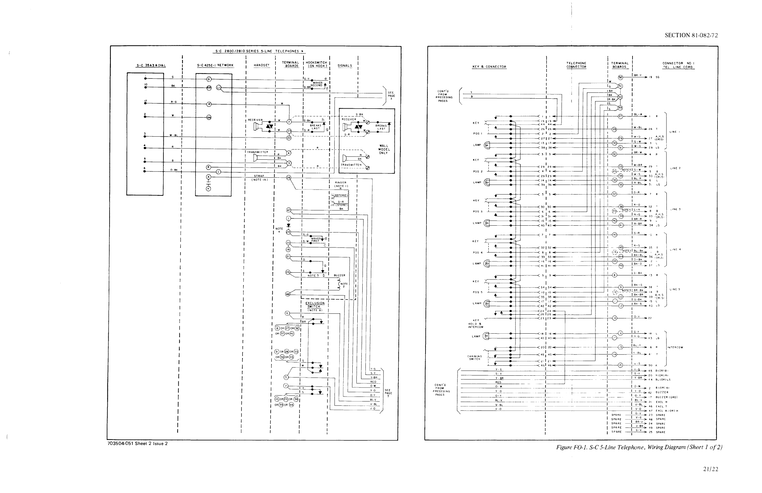
Figure
F0-1. S-C5-Line Telephone,
Wiring
Diagram (Sheet
1of2)
21/22
TCI Library www.telephonecollectors.info
This manual suits for next models
27
Table of contents
Other Stromberg-Carlson Telephone manuals

Popular Telephone manuals by other brands


Aastra
Aastra Aastra 610d Quick user guide

Curtis
Curtis TID-855 Owner's Manual and Operating Instructions

AT&T
AT&T Classic Mail Quick reference card

Philips
Philips DECT221 Declaration of conformity

Aastra
Aastra BLUESTAR 8000I Pbx-mode administrator guide

Jabra
Jabra CRUISER2 HSF002 Declaration of conformity