Stromberg-Carlson 1700-3 User manual
T-1094
ISSUE 2
STAQMBEAG-CA~LSQN
17DD·•
TH~••-LIN•
•X•CUTIV•
T•L•PHONll
installation and maintenance
in.~truction.~
TCI Library: www.telephonecollectors.info

STADMBEAG-CAALSDN
1700·!1
THREE-LINE
EXEICUTIVE
TELEPHONE
installation and maintenance instructions
TCI Library: www.telephonecollectors.info
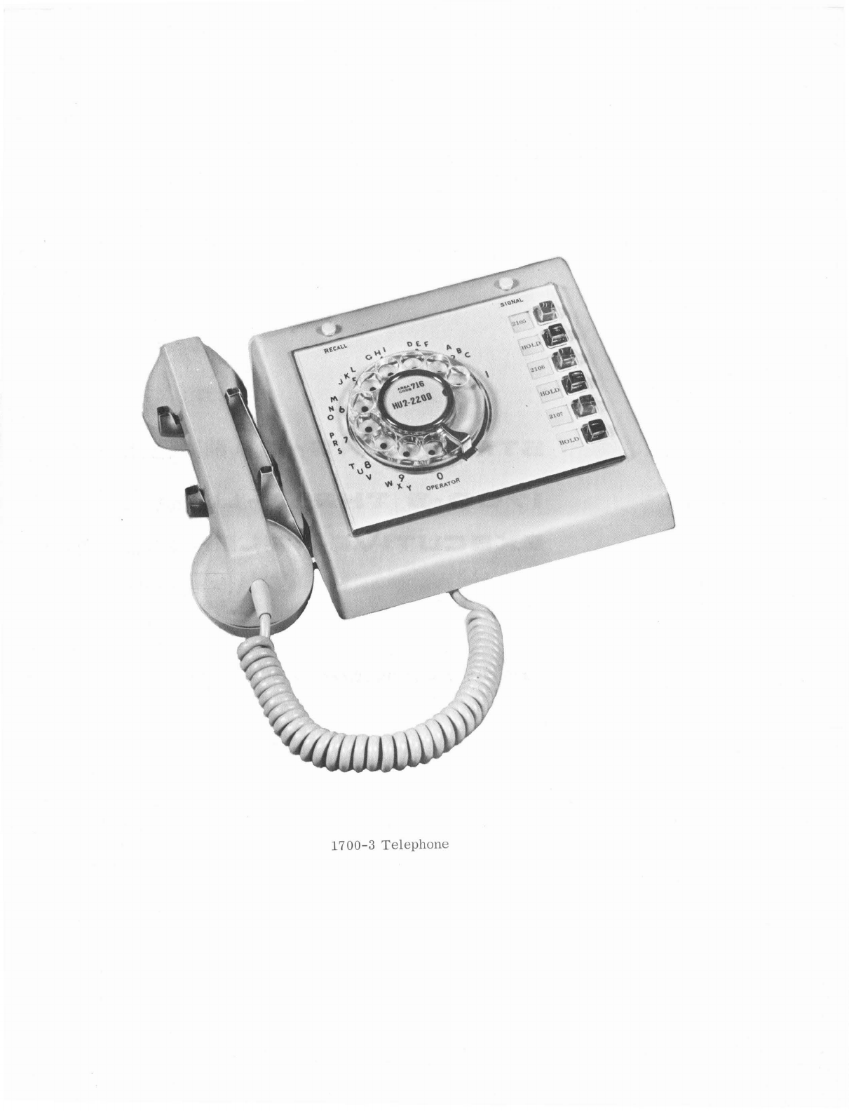
17
00-3
Telephone
TCI Library: www.telephonecollectors.info
Types
of
Telephones
Optional
Features
Operation
Types
of
Ringing
Installation
of
Telephone
Installation
of
Ringer
TABLE
OF
CONTENTS
SECTION
I
GENERAL
SECTION
II
INSTALLATION
Installation
of
Manual
Exclusion
for
Privacy
Feature
Installation
of
Manual
Exclusion
for
Intercom
Use
Busy
Lamp
Installation
Paragraph
1
2
3
4
5
G
7
8
9
SECTION
III
TELEPHONE
MAINTENANCE
General
Housing
Hookswitch
Dials
Signal
and
Recall
Key
Assembly
Replacement
Key
Assembly
Replacement
Line
Hold
Release
Adjustment
Neon
Lamp
Replacement
Ordering
Information
SECTION
IV
DIAL
MAINTENANCE
General
Replacement
of
Parts
Lubrication
Disassembly
of
Dial
Mechanism
Reassembly
of
Dial
Mechanism
Adjustment
Parts
List
DE-400
Dial
iii
10
11
12
13
14
15
lG
17
18
19
20
21
22
23
24
25
1
1
2
5
7
7
7
8
8
8
!)
19
21
21
22
23
23
24
28
TCI Library: www.telephonecollectors.info

LIST
OF
ILLUSTRATIONS
Three
Stations
with
Intercom
Extension,
Two
Outside
Lines,
Busy
Lamps,
Dial
Intercom
and
Ringer
or
Common
Audible
Signal
Three
Stations
with
Intercom
Extension,
Two
Outside
Lines,
Manual
Intercom,
Coded
Buzzer
System
Ringer
or
Common
Audible
Signal
and
Busy
Lamps
Three
Station
with
Intercom
Extension,
Three
Outside
Lines
with
Manual
Intercom
using
Manual
Exclusion
Switch,
Ringer
or
Common
Audible
Signal
Wiring
Diagram.
Typical
Three-
Line
Installation
with
Common
Audible
Signals
in
Telephone.
Wiring
Diagram.
Typical
Manual
Intercom
Installation
Wiring
Diagram.
Manual
Exclusion
at
Station
One
on
Line
One
Wiring
Diagram
Typical
Busy
Lamp
Installation
Wiring
Diagram.
Telephone
to
Dial
Selective
Intercom
Wiring
Diagram.
1700-3A
Telephone
Identification
of
Parts.
17
00-3A
Telephone
Bridge
and
Spring
Assembly
DE400
Dial
Bridge
and
Spring
Assembly
DE400A
Dial
Identification
of
Parts
DE 400A
Dial
iv
Figure
1
2
3
4
5
6
7
8
9
10
11
12
13
9
10
10
11
12
13
14
15
16
17
25
25
27
,,
TCI Library: www.telephonecollectors.info

SECTION
I
GENERAL
1.
TYPES
OF
TELEPHONES
a.
1700-3.
The
17
00-3
is
a
three-line
telephone
with
hold
on
each
line.
The
telephone
can
be
used
for
any
three-line
situation.
One
line
can
be
used
for
manual
intercom,
with
signaling
being
accomplished
through
use
of
the
signaling
button
located
above
the
line
keys.
Dial
selective
intercom
can
be
used
on
one
line
with
signaling
being
accomplished
by
use
of
the
dial.
Dial
selective
intercom
leaves
the
signal
button
free
for
signaling
a
secretary
or
other
uses.
If
three
central-office
or
PBX
lines
are
desired,
and
manual
exclusion
is
not
required
it
is
possible
through
the
use
of
the
manual
exclusion
switch,
to
have
intercom.
The
recall
button,
located
above
the
dial,
permits
signaling
for
operator
assistance
without
loss
of
a
call.
Incoming
calls
are
identified
by
the
neon
lamps
located
below
the
line
key,
which
flash
and
illuminate
the
line
key
of
the
called
line
b.
1700-3A.
The
key
assembly
of
the
1700-3
has
been
modified
to
prevent
paralleling
of
lines
during
switching.
Paralleling
of
lines
can
cause
false
call
transfer
in
the
F-50A
Dial
PBX
or
false
ring
trip
in
other
systems.
No
change
has
been
made
to
the
method
of
mounting
or
wiring
the
key
assembly;
the
old
and
new
assembly
are
completely
interchangeable.
Stock
numbers
for
the
key
assembly
will
not
change,
however,
the
code
number
for
the
key
assembly
(395)
and
telephone
(1700-3)
will
be
suffixed
with
"A"
(395A
key
assembly
and
l
700-3A
telephone).
2.
OPTIONAL
FEATURES
a.
A
manual
exclusion
button
can
be
added
to
provide
"private
line"
facilities
for
any
one
line
associated
with
each
telephone.
b.
A
common
audible
signal
can
be
installed
within
the
telephone
to
provide
an
audible
ringing
signal
for
incoming
calls
on
any
line.
Flashing
of
the
neon
lamp,
in
the
line
button,
identifies
the
line
being
rung.
The
neon
lamps
are
standard
equipment
and
operate
from
the
ringing
voltage
on
the
line.
c.
When
a
common
audible
signal
is
not
used,
a
ringer
will
be
required
on
each
line.
The
ringers
can
sould
alike;
the
flashing
of
the
line
button
will
identify
the
line.
d.
Lamps
can
be
installed
in
the
sockets
under
the
hold
buttons
to
provide
busy
line
identification.
A
step-down
transformer
is
required.
e.
Manual
intercom
requires
a
power-supply
for
ringing
and
talking
voltage,
and
a
buzzer
in
each
telephone
for
manual
intercom
signaling.
I
TCI Library: www.telephonecollectors.info

f.
Dial
selective
intercom
requires
the
use
of
a
suitable
intercom
system.
The
common
audible
signal
when
used,
will
provide
the
required
signaling.
An
intercom
buzzer
is
not
re-
quired
on
dial
selective
intercom.
3.
OPERATION
a.
Answering
an
Incoming
Call.
The
ringer
will
sound
and
a
lamp
under
one
of
the
line
buttons
will
flash
identifying
the
line
with
the
incoming
call.
Depress
this
line
button
which
will
lock
down
and
release
any
other
line
button
previously
depressed.
The
line
buttons
are
mechanically
interlocked
to
prevent
de-
pressing
of
more
than
one
line
button
at
a
time.
Lift
the
handset
from
the
cradle.
It
will
be
connected
to
the
selected
line.
b.
Releasing
a
Call.
When
the
call
is
completed,
replace
the
handset
in
the
cradle
to
release
the
connection.
The
line
key
will
remain
depressed,
and
a
subsequent
call
on
this
line
can
be
answered
by
simply
removing
the
handset
from
the
cradle.
c.
Holding
a
Call.
To
hold
a
call,
depress
the
hold
button
immediately
below
the
line
button
for
the
line
to
be
held.
This
places
a
"hold"
condition
on
this
line
and
release
the
line
button.
d.
Manual
Intercom.
To
operate
the
manual
intercom,
depress
the
line
button
designated
intercom
and
by
signaling
a
predetermined
code
with
the
signal
button,
the
called
party
will
answer.
e.
Recall
Button.
To
signal
for
operator
assistance
without
losing
a
call,
depress
the
recall
button
several
times
rapidly.
f.
Manual
Exclusion
Option.
To
engage
a
private
line,
depress
the
line
key
on
the
line
offering
manual
exclusion
and
pull
the
manual
exclusion
switch
out.
When
the
handset
is
replaced
on
the
cradle,
the
manual
exclusion
switch
will
automatically
return
to
the
"OFF"
position.
_g.
Manual
Intercom
Through
Exclusion
Switch.
The
manual
exclusion
switch
is
available
for
use
as
an
intercom
switch
if
necessary.
The
intercom
is
operated
by
pulling
this
switch
out
and
signaling
the
desired
party
through
the
buzzer
code.
When
the
handset
is
replaced,
the
switch
is
restored
in
the
normal
position.
4.
TYPES
OF
RINGING
The
1700-3
telephone
will
accept
either
the
common
audible
signal,straight-line
gong
ringer
or
buzzer.
2
TCI Library: www.telephonecollectors.info
SECTION
II
INSTALLATION
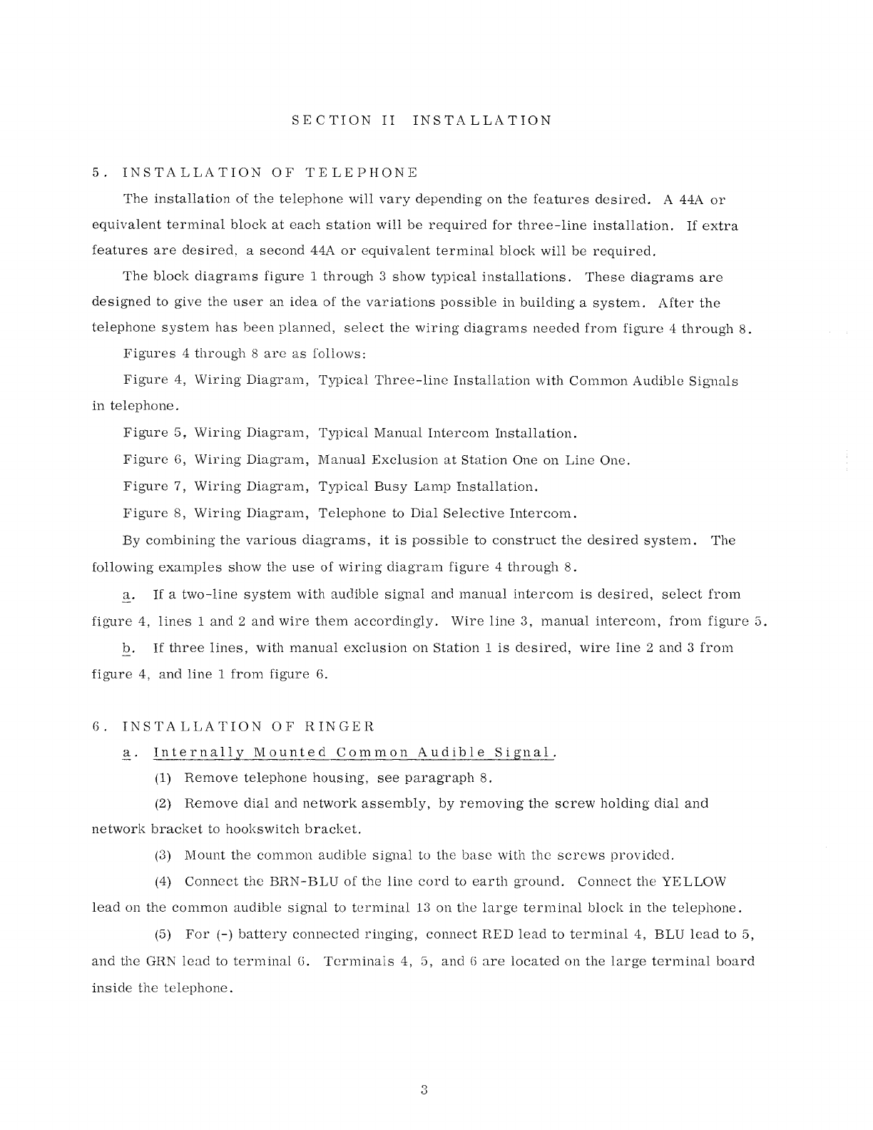
5.
INSTALLATION
OF
TELEPHONE
The
installation
of
the
telephone
will
vary
depending
on
the
features
desired.
A 44A
or
equivalent
terminal
block
at
each
station
will
be
required
for
three-line
installation.
If
extra
features
are
desired,
a
second
44A
or
equivalent
terminal
block
will
be
required.
The
block
diagrams
figure
1
through
3
show
typical
installations.
These
diagrams
are
designed
to
give
the
user
an
idea
of
the
variations
possible
in
building
a
system.
After
the
telephone
system
has
been
planned,
select
the
wiring
diagrams
needed
from
figure
4
through
8.
Figures
4
through
8
are
as
follows:
Figure
4,
Wiring
Diagram,
Typical
Three-line
Installation
with
Common
Audible
Signals
in
telephone.
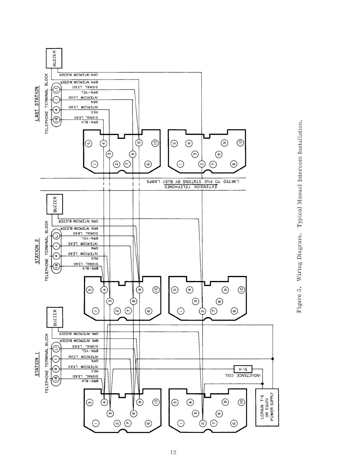
Figure
5,
Wiring
Diagram,
Typical
Manual
Intercom
Installation.
Figure
6,
Wiring
Diagram,
Manual
Exclusion
at
Station
One
on
Line
One.
Figure
7,
Wiring
Diagram,
Typical
Busy
Lamp
Installation.
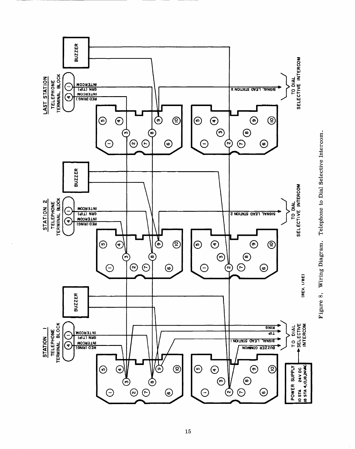
Figure
8,
Wiring
Diagram,
Telephone
to
Dial
Selective
Intercom.
By
combining
the
various
diagrams,
it
is
possible
to
construct
the
desired
system.
The
following
examples
show
the
use
of
wiring
diagram
figure
4
through
8.
a.
If
a
two-line
system
with
audible
signal
and
manual
intercom
is
desired,
select
from
figure
4,
lines
1
and
2
and
wire
them
accordingly.
Wire
line
3,
manual
intercom,
from
figure
5.
b.
If
three
lines,
with
manual
exclusion
on
Station
1
is
desired,
wire
line
2
and
3
from
figure
4,
and
line
1
from
figure
6.
6.
INSTALLATION
OF
RINGER
a.
Internally
Mounted
Common
Audible
Signal.
(1)
Remove
telephone
housing,
see
paragraph
8.
(2)
Remove
dial
and
network
assembly,
by
removing
the
screw
holding
dial
and
network
bracket
to
hookswitch
bracket.
(3)
Mount
the
common
audible
signal
to
the
base
with
the
screws
provided.
(4)
Connect
the
BRN-BLU
of
the
line
cord
to
earth
ground.
Connect
the
YELLOW
lead
on
the
common
audible
signal
to
terminal
13
on
the
large
terminal
block
in
the
telephone.
(5)
For
(-)
battery
connected
ringing,
connect
RED
lead
to
terminal
4,
BLU
lead
to
5,
and
the
GRN
lead
to
terminal
6.
Terminals
4,
5,
and
6
are
located
on
the
large
terminal
board
inside
the
telephone.
3
TCI Library: www.telephonecollectors.info
(G)
For
ground
connected
ringing,
connect
RED
lead
to
terminal
1,
BLU
lead
to
term-
inal
2,
and
the
GRN
lead
to
terminal
3.
Terminals
1, 2
and
3
are
located
on
the
large
terminal
board
inside
the
telephone.
Connect
a
strap
between
terminals
1
and
3
and
2
and
5
on
the
common
audible
signal
as
shown
on
wiring
diagram,
figure
9.
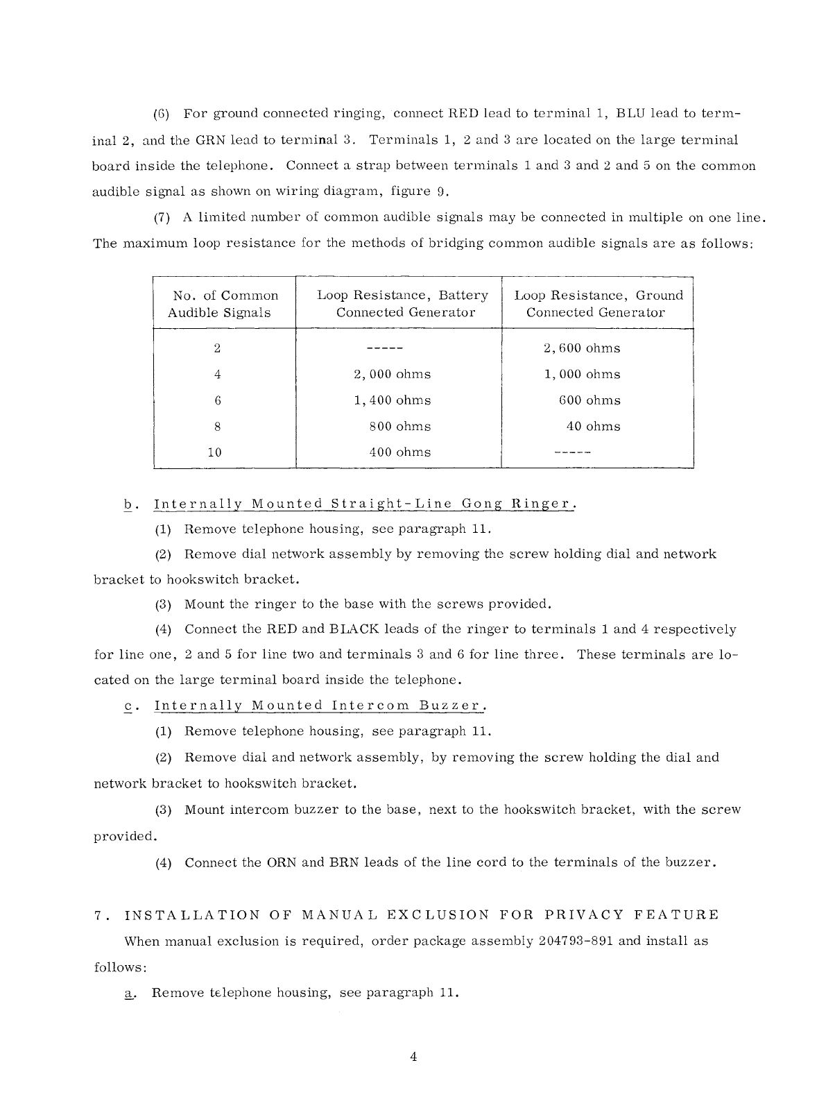
(7) A
limited
number
of
common
audible
signals
may
be
connected
in
multiple
on
one
line.
The
maximum
loop
resistance
for
the
methods
of
bridging
common
audible
signals
are
as
follows:
No.
of
Comn10n
Loop
Resistance,
Battery
Loop
Resistance,
Ground
Audible
Signals
Connected
Generator
Connected
Generator
2
-----
2, 600
ohms
4
2,
000
ohms
1, 000
ohms
G
1,
400
ohms
GOO
ohms
8
800
ohms
40
ohms
10
400
ohms
-----
b.
Internally
Mounted
Straight-Line
Gong
Ringer.
(1)
Remove
telephone
housing,
see
paragraph
11.
(2)
Remove
dial
network
assembly
by
removing
the
screw
holding
dial
and
network
bracket
to
hookswitch
bracket.
(3)
Mount
the
ringer
to
the
base
with
the
screws
provided.
(4)
Connect
the
RED
and
BLACK
leads
of
the
ringer
to
terminals
1
and
4
respectively
for
line
one,
2
and
5
for
line
two
and
terminals
3
and
6
for
line
three.
These
terminals
are
lo-
cated
on
the
large
terminal
board
inside
the
telephone.
c.
Internally
Mounted
Intercom
Buzzer.
(1)
Remove
telephone
housing,
see
paragraph
11.
(2)
Remove
dial
and
network
assembly,
by
removing
the
screw
holding
the
dial
and
network
bracket
to
hookswitch
bracket.
(3)
Mount
intercom
buzzer
to
the
base,
next
to
the
hookswitch
bracket,
with
the
screw
provided.
(4)
Connect
the
ORN
and
BRN
leads
of
the
line
cord
to
the
terminals
of
the
buzzer.
7.
INSTALLATION
OF
MANUAL
EXCLUSION
FOR
PRIVACY
FEATURE
When
manual
exclusion
is
required,
order
package
assembly
204793-891
and
install
as
follows:
~·
Remove
telephone
housing,
see
paragraph
11.
4
TCI Library: www.telephonecollectors.info
b.
Mount
the
exclusion
switch
to
the
telephone
base
(lower
left-corner)
using
the
screws
provided.
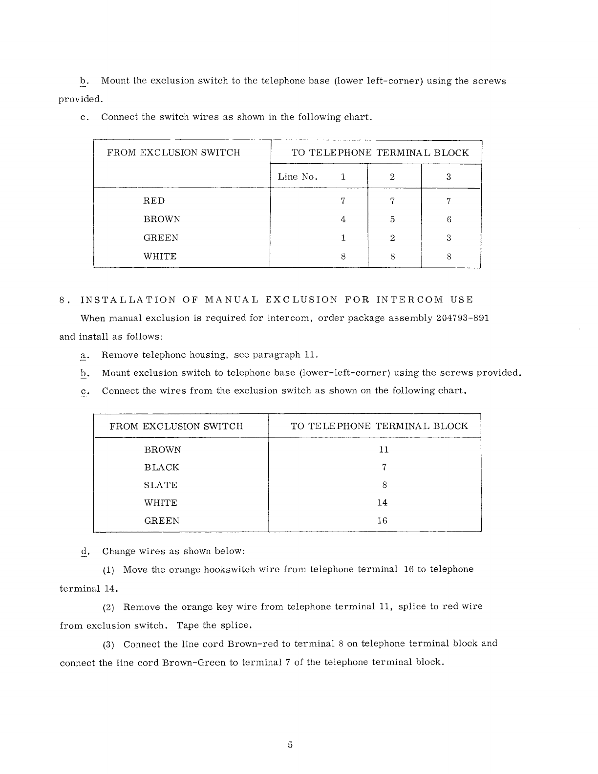
c.
Connect
the
switch
wires
as
shown
in
the
following
chart.
FROM
EXCLUSION
SWITCH
TO
TELEPHONE
TERMINAL
BLOCK
Line
No.
1 2 3
RED
7 7 7
BROWN 4 5 6
GREEN
1 2 3
WHITE
8 8 8
8.
INSTALLATION
OF
MANUAL
EXCLUSION
FOR
INTERCOM
USE
When
manual
exclusion
is
required
for
intercom,
order
package
assembly
204793-891
and
install
as
follows:
a.
Remove
telephone
housing,
see
paragraph
11.
b.
Mount
exclusion
switch
to
telephone
base
(lower-left-corner)
using
the
screws
provided.
c.
Connect
the
wires
from
the
exclusion
switch
as
shown
on
the
following
chart.
FROM
EXCLUSION
SWITCH
TO
TELEPHONE
TERMINAL
BLOCK
BROWN 11
BLACK
7
SLATE
8
WHITE
14
GREEN
16
d.
Change
wires
as
shown
below:
(1)
Move
the
orange
hookswitch
wire
from
telephone
terminal
16
to
telephone
terminal
14.
(2)
Remove
the
orange
key
wire
from
telephone
terminal
11,
splice
to
red
wire
from
exclusion
switch.
Tape
the
splice.
(3)
Connect
the
line
cord
Brown-red
to
terminal
8
on
telephone
terminal
block
and
connect
the
line
cord
Brown-Green
to
terminal
7
of
the
telephone
terminal
block.
5
TCI Library: www.telephonecollectors.info
9.
BUSY
LINE
LAMP
INSTALLATION
a.
When
busy
lamp
indication
is
required,
order
(3)
three
lamps
211108-000
and
trans-
former
power
supply
202897-642.
b.
Remove
bezel,
face
plate
and
face
mat
assembly.
With
care
first
lift
the
bezel
from
the
top
of
the
housing,
then
raise
upward
and
lift
out.
c.
Remove
the
lamp
shield.
d.
Insert
the
busy
lamps
into
the
sockets.
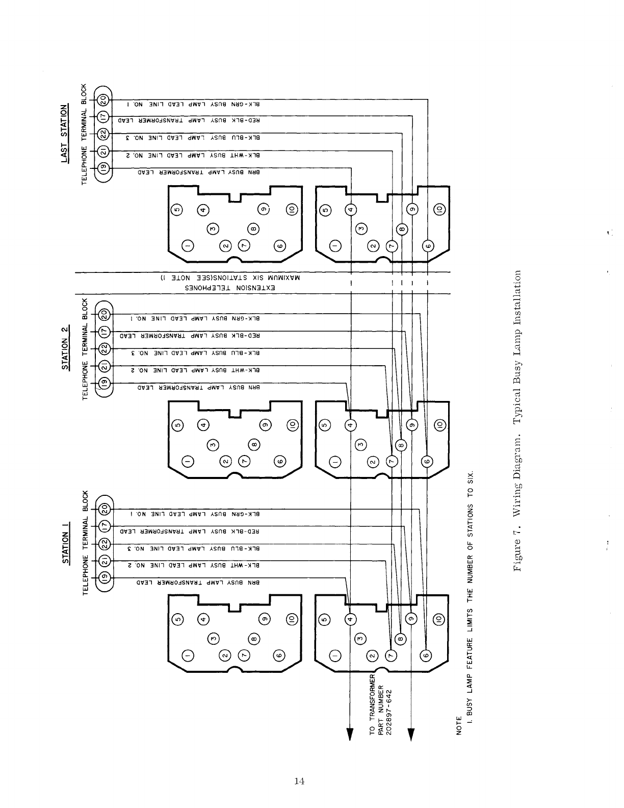
e.
Connect
lamp
leads
and
transformer
leads
as
shown
in
figure
7.
6
TCI Library: www.telephonecollectors.info
SECTION
III
TELEPHONE
MAINTENANCE
10.
GENERAL
Make
a
visual
inspection
of
the
exterior
and
interior
of
the
telephone.
Look
for
obvious
defects
such
as
worn,
loose
or
broken
parts;
obstruction
of
moving
parts;
or
the
presence
of
foreign
matter
that
could
interfere
with
proper
operation.
11.
HOUSING
To
remove
the
housing,
first
remove
the
bezed,
face
mat
and
face
plate
by
lifting
the
bezel
from
the
top
of
the
housing
first,
then
raise
upward
and
lift
out.
Loosen
the
two
housing
screws
at
the
rear
of
the
telephone
housing,
and
lift
housing
up
and
forward.
12.
HOOKSWITCH
a.
Tension
Spring
Adjustment.
To
check
spring
tension,
remove
the
housing,
paragraphll.
Replace
the
handset
on
the
cradle.
The
hookswitch
lever
should
rest
on
the
mounting
bracket.
To
increase
the
tension
of
the
spring,
bend
the
adjustment
arm
forward
slightly.
To
decrease
the
tension,
bend
the
arm
back-
ward
slightly.
b.
Contact
Spring
Adjustment.
The
hookswitch
consists
of
three
sets
of
twin-contact
springs.
Sequence
of
"W"
contact
operation
is
not
important;
"X"
contact
must
operate
before
"Y"
contact.
The
springs
have
a
slight
curve
and
the
upper
springs
of
the
combination
should
have
a
slight
follow
when
operating.
In
adjusting
these
springs,
be
sure
that
the
bar
contacts
on
the
lower
spring
of
the
combination,
simultaneously
engage
the
bar
contacts
of
the
upper
springs.
c.
Hookswitch
Replacement.
To
replace
the
hookswitch
assembly,
part
number
200128-609,
proceed
as
follows:
(1)
Remove
telephone
housing,
paragraph
8.
(2)
Disconnect
hookswitch
leads.
(3)
Remove
the
screw
in
the
upper
left-hand
corner
of
the
dial
bracket
and
slide
the
dial
bracket
back
to
disengage
from
base.
(4)
Remove
the
hookswitch
tension
spring;
and
slide
the
shaft
out.
(5)
Remove
the
two
screws
holding
the
hookswitch
bracket
to
the
base.
(6)
Replace
with
new
hookswitch
assembly
and
assemble
by
reversing
the
above
procedure.
7
TCI Library: www.telephonecollectors.info
13.
DIALS
To
replace
the
dial,
part
number
202145-511,
proceed
as
follows:
a.
Remove
the
telephone
housing,
paragraph
11.
b.
Disconnect
the
dial
leads.
c.
Remove
the
screw
in
the
upper
left
hand
corner
of
the
dial
bracket
and
slide
the
dial
bracket
back
to
disengage
from
base.
d.
Remove
the
two
screws
holding
the
dial
to
the
dial
bracket.
e.
Replace
with
new
dial
and
assemble
by
reversing
the
above
procedure.
f.
For
maintenance,
repair
and
adjustment
of
dial,
see
Section
III
of
this
manual.
14.
SIGNAL
AND
RECALL
KEY
ASSEMBLY
REPLACEMENT
To
replace
the
signal
and
recall
key
assembly,
part
number
206011-511,
proceed
as
follows:
a.
Remove
the
telephone
housing,
paragraph
11.
b.
Remove
the
two
screws
holding
the
signal
and
recall
assembly
plate
to
the
dial
assembly.
c.
Disconnect
the
two
leads
to
both
switches.
d.
Replace
with
new
assembly
and
assemble
by
reversing
the
above
procedure.
15.
KEY
ASSEMBLY
REPLACEMENT
To
replace
key
assembly,
part
number
206011-501,
proceed
as
follows:
a.
Remove
the
telephone
housing,
paragraph
11.
b.
Disconnect
key
assembly
leads,
by
removing
plug
at
rear
of
set.
c.
Remove
the
two
screws
holding
the
key
assembly
to
the
key
mounting
bracket.
d.
Slide
the
short
connecting
rod
from
the
hold
return
cam.
e.
Replace
with
new
key
assembly
and
assemble
by
reversing
the
above
procedure.
16.
LINE
HOLD
RELEASE
ADJUSTMENT
The
hold
key
is
mechanically
restored
to
normal
by
the
operation
of
the
hookswitch
to
the
"on-hook"
position.
If
the
hold
key
does
not
release,
adjust
as
follows:
a.
Remove
the
telephone
housing,
paragraph
11.
b.
Loosen
the
connecting
plate
screw,
upper
right-hand
corner
of
telephone
base.
c.
With
the
handset
removed,
manually
depress
the
hookswitch
so
that
the
long
connecting
rod
moves
the
connecting
plate
to
the
right
slightly.
d.
Tighten
the
connecting
plate
screw
securely.
e.
Depress
at
least
two
hold
keys
and
replace
the
handset.
Pressure
of
the
handset
should
restore
the
hold
keys
to
normal.
f.
If
keys
still
do
not
operate
properly,
repeat
steps
Q
through~·
8
TCI Library: www.telephonecollectors.info

17.
NEON
LAMP
REPLACEMENT
To
replace
the
neon
line-indicating
lamp,
use
part
number
200162-299,
and
proceed
as
follows:
a.
Remove
the
bezel,
face
plate
and
mat
assembly
by
lifting
up
and
forward.
b.
Remove
the
lamp
shield.
c.
Remove
the
lamps
by
clipping
the
neon
lamp
leads
as
close
to
the
socket
as
possible.
d.
Insert
the
new
lamp
into
the
socket.
The
replacement
lamp
is
socket
based
and
made
for
this
application.
e.
Replace
the
lamp
shield
and
bezel
assembly.
,.....
0
,.....
I l
~
~
-)
~
,
.....
f-
c
'-'-
,
.....
H
[).-.
~r-~
c.._
[).-.
=
l'-'J -I
'--"
'-'
r
I -" -"
I z z
I
:::;
::;
::::;
:::;
I
~-N~~
~XS_.l~l~N
_
O~_Tl_2_N
~
~
H!J
4
z
Z0
~(ii
~w
H!J
o"
~
u~
INTERCOM
~
10
STATION
OLJ
DIAL
SELECTOR
O INTERCOM
--OR-0
rn
1
!L
s~:~~~~R
§ INTERCOM
-OR-0
2-10
PX
0
INTERCOM 0
INTERCOM
0
-OR-0
4-
20
PX
0
INTERCOM 8 TO EXTENSION
TELEPHONES
~~
POWER
SUPPLY
10
VAC
BUSY
LAMPS
(SEE
NOTE
I)
-
NOTE
I_
POWER
SUPPLYS
NEEDED
10
STATION}24
VDC
18
STATION
4,
10, 18,
24
VAC
2-10
PBX}24VDC
4-20
PBX 3 ANO 6 AMP
>-
'-'-
'-
H
>-+->->-
H
-"
..
z z
:::;
:::;
EXTENSION TELEPHONES
-
~-,
'
-
-
--·
TO
ADDITIONAL
EXTENSIONS
Figure
1.
Three
Stations
with
Intercom
Extension,
Two
Outside
Lines,
Busy
Lamps,
Dial
Intercom
and
Ringer
or
Common
Audible
Sig1ial.
9
TCI Library: www.telephonecollectors.info
EXTENSION TELEPHONES
LINE I
LINE 2
Figure
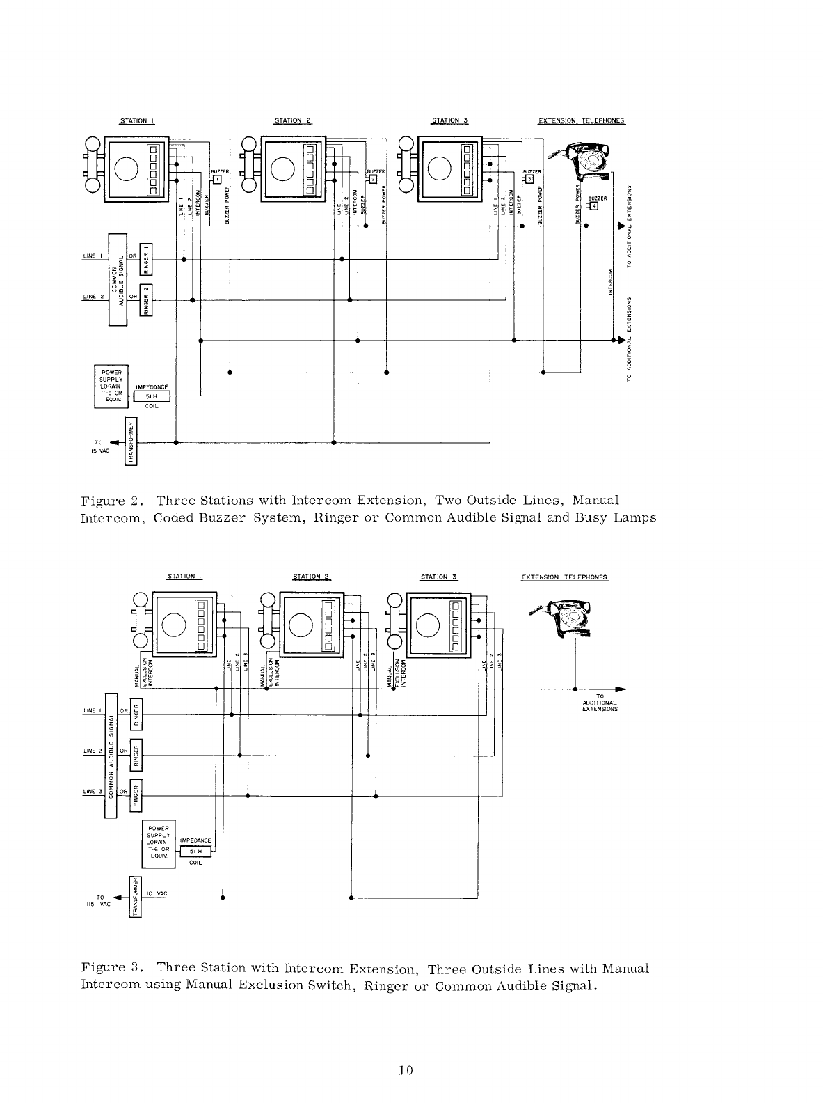
2.
Three
Stations
with
Intercom
Extension,
Two
Outside
Lines,
Manual
Intercom,
Coded
Buzzer
System,
Ringer
or
Common
Audible
Signal
and
Busy
Lamps
EXTENSION TELEPHONES
~
~
TO
ADDITIONAL
EXTENSIONS
Figure
3.
Three
Station
with
Intercom
Extension,
Three
Outside
Lines
with
Manual
Intercom
using
Manual
Exclusion
Switch,
Ringer
or
Common
Audible
Signal.
10
TCI Library: www.telephonecollectors.info

f-'
f-'
-
.....
·-··
TELEPHONE TERMINAL
BLOCK
I I
(
@(4)(~@(0(3)@)
-
"'
N N
"'
~:a
"'
"' "'
-
z z
"' "' "'
:IE
z
z
:::;
z z z
:IE
"
:::; :::;
0-
:::; :::;
:::;
u"'
8 a a
~
0: 0:
3"'
z
~
z
~
0::
a:
I-
E
;::
'P
~
I ©
I-
0
><
:::;
z 5
zo
I
:r
"'
..J
"'
0::
..J
0::
::>
;i::
a::
ID
>-
" ID ID
<l
RING
LINE I I I
©
...
RING
LINE 3 -
3 3
RING LINE 2 2 2
TIP
LINE
2 ) r )
TIP
LINE 3 0 0
8 8
0 -
TIP
LINE
I 6 6
@
'0
0
CD
© -
~
3 3
® ®
,0
0
© 0 ©
..
©
\ @ ©
NOTES
I.
FOR
DIAL
INTERCOM
ON
LINE 3
WIRE
LINE I
AND
LINE 2
FROM
THIS FIGURE
AND
LINE 3 INTERCOM
FROM
FIGURE 8
0
0
[
0
@
©
0
0
@
2.
FOR
MANUAL EXCLUSION OPTION
WIRE
MANUAL
EXCLUSION
SWITCH
FROM
FIGURE
6
3.
FOR
MANUAL INTERCOM
ON
LINE 3
WIRE
LINE I
AND
LINE 2
FROM
THIS
FIGURE:
WIRE
LINE 3
FROM
FIGURE 5
-.
'ATION 2 LAST STATION
TELEPHONE TERMINAL
BLOCK
TELEPHONE TERMINAL
BLOCK
-
-
-
..
I
(
C
6
)@(5)C~00@)
-
"'
z
:::;
8
z
a:
;::
:r
;i::
"'
N N
"'
-
~
ct
"' "'
"'
"' "'
:IE
z
z z z z
~
:IE
"
:::;
:::;
:::;
o-
:::;
..J
u"'
a a
~
0:
0:
~~
z z
a:
~
!:; E E
0
"'
..J
z
=>
zo
"'
..J
"'
0:: ..J a::::>
a::
ID
>-
" ID
ID
<l
-
"'
N N
"'
-z
0
"'
"'
"'
"'
"' "'
:IE
z z z z z
:IE
:::; :::;
:::;
z
:::; :::;
0
8 a a
:::;
u
z z z
0:
0: 0:
::>
a: a: a:
I- I-
E
..J
ID
;::
0
><
:i
z
::>
z
:r
"'
..J
"'
a::
..J
a::
;i::
a::
ID
>-
"
ID ID
-
iD
lJJ
I-
0
z 0
lJJ
lJJ
~
Cf) ©
lJJ
z
0 3
:c
c..
lJJ
_J
lJJ
I-
© @
4.
FOR
BUSY
LAMP FEATURE
WIRE
LINES
TO
THIS
FIGURE
AND
BUSY
LAMPS
FROM
FIGURE 7
5.
BUSY
LAMP FEATURE LIMITS THE NUMBER
OF
STATIONS
TO
SIX.
Figure
4.
Wiring
Diagram.
Typical
Three-Line
Installation
with
Common
Audible
Signals
in
telephone.
TCI Library: www.telephonecollectors.info
z
0
~
(/)
1-
(/)
<(
...I
N
z
0
~
(/)
z
0
~
1-
(/)
Ir
w
N
N
::::i
ID
Ir
w
N
N
::::i
ID
Ir
w
N
N
::::i
ID
!13ZZn8
WO:J!l3.LNI
N!l8
01131
111N91S
13A-
N!18
01131 WO:J!l3.LNI
N!I!>
01131 WO:J!l3.LNI
03!1
01131
111N91S
~18
-N!l8
G
!13Zzn8
WO:J!13.LNI
N!l8
01131
111NDIS
13A-N!18
01131
WO:J!13.LNI
N!ID
01131
WO:J!13.LNI
03!1
01131
111N91S
~18-N!l8
G
N!IO
N!l8
01131 111NDIS
13A-N!l8
01131
WO:J!13.LNI
N!lD
01131 WO:J!l3.LNI
03!1
01131
111NDIS
~18-N!l8
G
ee
ee
ee
® ®
G
SdWVl
ASn8
A8
SNOl.1'1.LS
3/\1.:1
0.1
03.llWll
S3NOHd313.l
NOISN3.1X3
® ®
G
H
19
110::>
3:JNV.l:JnoNI
® ®
G
12
TCI Library: www.telephonecollectors.info

LINE I
RING
© 0
0 ©
.....
w LINE I
TIP
6
CD
© 0
0 ©
©
STATION
I
TELEPHONE TERMINAL
BLOCK
z z
0 0
iii iii
::>
::>
--' --'
u u
x x
"' "'
--'
--'
<(
~
"'
::>
z
"'
z z
:::;
z
<( <(
:IE :IE
s
:::;
c z Ii:
"'
~
a:
E
z
I-
::>
a:
:I:
--'
m
3::
m
....._,
©
0
©
©
®
(@)
Figure
6.
,
© 0
0 ©
6
CD
© 0
0 ©
©
STATION 2
TELEPHONE TERMINAL
BLOCK
"'
"'
z
z
:::;
:::;
s
Ii: z
t:
a:
::>
j::
--'
:I:
m
3::
© I
©
®
@)
©
©
0
(@)
-
Cl)
z
0
s
Cl)
z
0
Cl)
z
IJ.J
I-
x
IJ.J
Manual
Exclusion
at
Station
One on
Line
One.
/_
© 0
0 ©
CD
© 0
0 ©
©
LAST STATION
TELEPHONE TERMINAL
BLOCK
"'
"'
z
z
:::;
--' s
Ii:
~
E
!!::
::>
I-
--'
:I:
m
3::
© I
©
0
@)
©
©
0
(@)
TCI Library: www.telephonecollectors.info
"'
u
0
.J
m I
"ON
3NJ1
01131
dl>ll111
Asn0
NIH>
->118
z
.J
0
<[
ti
z
01131
113WllO:ISNllll.l dl>lllll
Asn0
)118-0311
:ii
I-
a::
I/)
LL.I
£
"ON
3N11
01131
dl>lllll >.sn0
n10->110
1--
I-
LL.I
I/)
ct
z i
"ON
3N11
01131
dl>lllll
Asn0
.lHM->118
0
....I
::c
!l.
LL.I
01131 113WllO:ISNllll.l dl>lllll ASn8
Nll8
.J
LL.I
1--
e e e ® e
e e I i
8
ee
e 8
~
(I
3.lON
33SlSNOl.111.1S XIS wnJNIXlfL'l 0
"'°"
S3NOHd313.1 NOISN3.1X3
.....,
c:l
-
"'
-
u
c:l
0
.....,
.J
UJ
m I
"ON
3Nll
01131
dWlll
Asn0
Nll9->118
~
.J
>-<
N
<[
0..
z 01131 113WllO:ISNllll.l
dr-llll
Asn0
)118-0311
z :ii s
0
a::
c:l
~
LL.I
dr-lll1
Asn0
n10->110
H
1--
£
"ON
3Nll
01131
I-
LL.I
:>-,
I/)
z i
"ON
3Nll
01131
d1>11111
Asn0
.lHM-)118
UJ
0
;j
::c
!l.
~
LL.I
01131 113WllO:ISNllll.l dl>lllll ASn8
Nll8
.J
-
LL.I
c:l
1--
<:)
"'°"
~
e e e ® e
E--<
e e s
Cl!
8
88
e 8 H
bJJ
Cl!
~
"'°"
Q
en
bJJ
"'
0
~
u
1--
"'°"
9 H
en
"'°"
m z
~
.J
I ·oN
3Nll
01131 dl>lllll >.sn0
Nll9->118
0
<[
1--
z
i=!
z
:ii
01131
113WllO:ISNllll.l
dWlll
Asn0
)118-0311
en
t--
0
a::
(])
~
LL.I
LL.
1--
£
"ON
3Nll
01131 dl>lllll
Asn0
n18-ll18
0 H
I-
LL.I
a::
51
I/)
z i
"ON
3Nll
01131
dl>lllll
Asn0
.lHM->118
LL.I
·..-<
0 m
µ..
::c
::;;
!l.
::::i
LL.I
01131 113Wl!O:ISNllll.l dl>lllll ASn8
Nll8
z
.J
LL.I LL.I
1--
::c
1--
en
G e G ® e
1--
:ii
.J
e e
LL.I
a::
8 e 8 e 8
::::i
!;:(
LL.I
LL.
a::
!l.
LL.I
::;;
::;;
a::
<[
0::
LL.IN
.J
f2
m..,.
>-
en
::;;
""
Z
::JI
en
<[
z
t--
::::i
a::
(J)
m
l--1--
a>
LL.I
0
a::~
1--
0
1--
i'i':N
z
14
TCI Library: www.telephonecollectors.info
.....
Cl
0)
©
0
©
©
®
0
0©
0®
®
© @
POWER
SUPPLY
10
STA
24V
DC
18
STA 4,10,18,24-...C
STATION
TELEPHONE
TERMINAL BLOCK
i::IEI~
0:8
~8
-
a= a=
cW
zW
~~
~~
~
~1!
~
~I
a=
w
~I~
~1~
~
TO
DIAL
SELECTIVE
INTERCOM
BUZZER
0)
®
STATION 2
TELEPHONE
TERMINAL
BLOCK
(;::E-;e
~
8
~
ts
!!;a=-a=
cwzw
wl-a=l-
a=~llll!:
BUZZER
C0
©
0
LAST STATION
TELEPHONE
TERMINAL BLOCK
BUZZER
r===
I I I I I
l31----+--~
!REV.
I/BEi
®
0
© @
©
C0
@0
0©
®
© ®
N
~
!ii
ti)
c
~
...J
c
z
"
u;
~
TO
DIAL
SELECTIVE
INTERCOM
©
0
© @
0 ©
@©
@
Figure
8.
Wiring
Diagram.
Telephone
to
Dial
Selective
Intercom.
x
~
~
Iii
~
...J
cl
z
"
iii
~
TO
DIAL
SELECTIVE INTERCOM
TCI Library: www.telephonecollectors.info
Table of contents
Other Stromberg-Carlson Telephone manuals


