Strong Flow AG Series Manual
OPERATING AND MAINTENANCE
INSTRUCTIONS
28.9.2018
StrongFlow Oy
Domicile: Kaarina
Ahokylänkatu 3
Business ID: 2024125-8
FI-20780 Kaarina
VAT no: FI25511181
StrongFlow Oy
Ahokylänkatu 3
20780 Kaarina
Y-Tunnus 2024125-8
www.strongflow.fi
+358 20 730 1820
AG-250/330
Water softeners

Operating and maintenance manual
AG-CAB1035 Water softner
Sivu 2/22
StrongFlow Oy
Tel. +358 20 730 1820
Domicile: Kaarina
Ahokylänkatu 3
www.strongflow.fi
Business ID: 2024125-8
FI-20780 Kaarina
VAT no: FI25511181
1. GENERAL INFORMATION........................................................................................................ 3
2. INSTALLATION ........................................................................................................................ 4
2.1 Location selection.................................................................................................. 4
2.2 Filling resin to pressure vessel............................................................................... 5
2.3 Water line connections.......................................................................................... 5
2.4 Brine tank and tube connection ............................................................................ 6
3GENERAL CONTROLLER INSTRUCTION .................................................................................... 7
3.1 Controller display................................................................................................... 7
3.2 Controller buttons ................................................................................................. 8
4. PROGRAMMING CONTROLLER............................................................................................... 9
4.1 Initial power-up/ Re-initialization (reset) .............................................................. 9
4.2 Default settings.................................................................................................... 10
4.3 Additional settings (P9-P19) ................................................................................ 14
4.4 Cycle time programming...................................................................................... 15
4.4.1 Regeneration modes.................................................................................... 15
4.4.2 Manual regeneration ................................................................................... 15
5. START-UP OF THE FILTER AND VALVE................................................................................... 16
6. MAINTENANCE AND TROUBLESHOOTING ........................................................................... 17
6.1 Cleaning the automatic valve filter screen/net ................................................... 17
6.2 Changing the resin ............................................................................................... 17
6.3 Possible problems and causes ............................................................................. 18
7. ATTACHMENTS..................................................................................................................... 19
Attachment 1: Automatic valve configuration .......................................................... 19
Attachment 2: Exploded view and spare part list...................................................... 19

Operating and maintenance manual
AG-CAB1035 Water softner
Sivu 3/22
StrongFlow Oy
Tel. +358 20 730 1820
Domicile: Kaarina
Ahokylänkatu 3
www.strongflow.fi
Business ID: 2024125-8
FI-20780 Kaarina
VAT no: FI25511181
1. GENERAL INFORMATION
AG-CAB filter can be used for water softening and filtration of iron and manganese. Filters have fully
automatic operation principle and only regular refill of salt is needed. More detailed technical
information can be found from table 1.
Table 1. Technical information
The content of the delivery:
•Pressure vessel, diffusor with tube, automatic valve, drain tube, resin
•Brine tank, salt suction pipe, salt suction hose, regeneration salt
•Manual
250 330
Connections (filter)
DN
Flow rate l/min 32,7 57
Capacity
m3/°dH 120 200
Resin l 38 65
Rinse water l/rinse 350 470
Pressure index
bar
Working pressure, min/max.
bar
Water temperature, min/max.
°C
Ambient temperature, min/max.
°C
Electrical connections
V/Hz
Need for electric power
W
Height / diameter (filter)
mm 257 x 1385 334 x 1370
Widht / depth / height (brine tank)
mm
Brine tank volume
l85 85
AG
n. 4,8
380 x 380 x 790
20 / 10 (drain line)
10
2 / 6
2 / 38
5 / 40
230 / 50

Operating and maintenance manual
AG-CAB1035 Water softner
Sivu 4/22
StrongFlow Oy
Tel. +358 20 730 1820
Domicile: Kaarina
Ahokylänkatu 3
www.strongflow.fi
Business ID: 2024125-8
FI-20780 Kaarina
VAT no: FI25511181
2. INSTALLATION
2.1 Location selection
1. Install the filter to even surface and dry place that is equipped with large enough
drainage to handle the backwash water. Please note that the filter creates 700-
1300 litres of backwash water each time it regenerates.
2. For electrical connections there must be grounded power outlet 230V / 50Hz. Use
only the power AC adapter that is supplied.
3. Make sure there is enough room around the filter for possible maintenance.
4. Do not use filter or piping at temperatures above 40 °C. Filter should be protected
from freezing.
5. Please note that it’s on customers duty to install non-return valve to line of filtrated
water.
6. Filter may not be exposed to direct spray of water.
Operating and maintenance manual
AG-CAB1035 Water softner
Sivu 5/22
StrongFlow Oy
Tel. +358 20 730 1820
Domicile: Kaarina
Ahokylänkatu 3
www.strongflow.fi
Business ID: 2024125-8
FI-20780 Kaarina
VAT no: FI25511181
2.2 Filling resin to pressure vessel
Pressure vessel is filled with resin so that the threaded automatic valve is turned open. Diffusor tube
is detached from valve and left in its place inside the vessel. Upper end of diffusor tube is sealed
with suitable cap or tape and after that resin can be poured into the vessel. Seal from diffusor tube
is removed and automatic valve is turned in place. All pipe connections need to be checked before
filter is started.
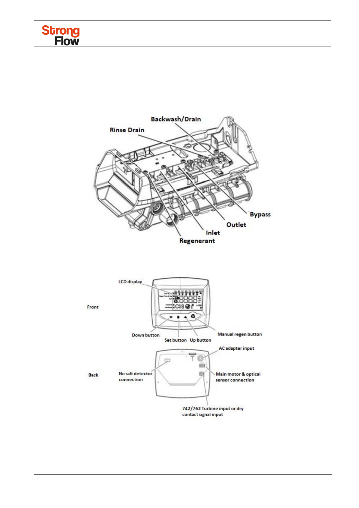
2.3 Water line connections
Filters inlet and outlet fittings are ¾” internal thread. Outlet fitting is marked with arrow. Drain line
fitting for 12,7 mm tube is pre-installed to valves drain line connection by supplier.
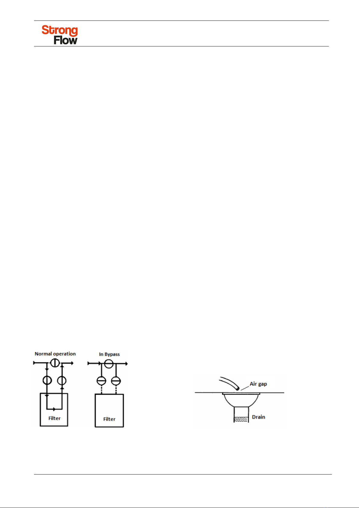
Its recommended that bypass line is installed between inlet and outlet lines to allow detaching of
filter for maintenance without interruptions in water supply (picture 1.).
Attach drain tube to fitting and run to drain so that siphon is avoided (picture 2). In ideal installation
the drain tube sets all the way to drain. If this is not possible, drain tube can be lifted to maximum
height of 1,8 meters if the tube length doesn’t exceed 4,6 meters. In this case the inlet water
pressure to filter needs to be over 2,8 bars.
Picture 1. Valve Bypass System Picture 2. Drain line connection
Operating and maintenance manual
AG-CAB1035 Water softner
Sivu 6/22
StrongFlow Oy
Tel. +358 20 730 1820
Domicile: Kaarina
Ahokylänkatu 3
www.strongflow.fi
Business ID: 2024125-8
FI-20780 Kaarina
VAT no: FI25511181
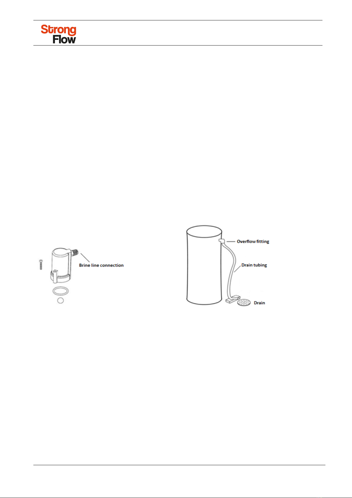
2.4 Brine tank and tube connection
Brine tank should be installed to even platform. Connect brine tanks suction tube (picture 3) to air checks
regenerant line connection. Before starting the filter that all connections are well prepared, and tubes /
piping have no places for leakage. Possible leakage in brine suction line can cause premature closure of
floating ball valve and excess brine left to bottom of brine tank.
Drain tube must be installed between brine tank and drain to further damages in possible overflow
situation of brine tank. Attach tube to overflow fitting and run to drain (picture 4).
Picture 3. Air check Picture 4. Overflow line connection
Operating and maintenance manual
AG-CAB1035 Water softner
Sivu 7/22
StrongFlow Oy
Tel. +358 20 730 1820
Domicile: Kaarina
Ahokylänkatu 3
www.strongflow.fi
Business ID: 2024125-8
FI-20780 Kaarina
VAT no: FI25511181
3 GENERAL CONTROLLER INSTRUCTION
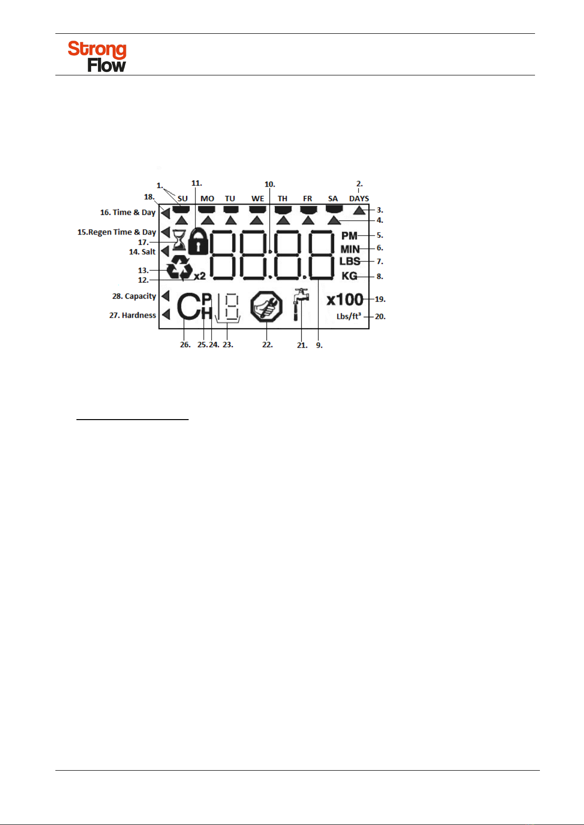
3.1 Controller display
Picture 5. Display icons
Description of Symbols
1. Day of week when regeneration takes place
2. Check (see chapter 3.2).
3. Shows interval for regeneration in days
4. Shows the days for regeneration
5. Not in use
6. Not in use
7. Shows how many grams of salt is used for each litre
of brine.
8. Not is use.
9. Shows the set values (e.g. current time, time for
regeneration etc.)
10. Separator for hours and minutes.
11. Shows if value is locked. When shown its not possible
to change the value in case.
12. Filter makes two regenerations in a row.
13. Regeneration process is running.
14. Not in use.
15. Time and date for regeneration when controller is in
normal mode and under programming.
16. Current time and date when controller is in normal
mode and under programming.
17. Shown when cam-axel is turning into new position
and new stage begins.
18. Status of the screen
19. Not in use.
20. Not in use.
21. Not in use.
22. Not in use.
23. Regeneration stage status
24. Not in use
25. Programming mode on.
26. Regeneration stage (together with 23.)
27. Not in use.
28. Capasity.

Operating and maintenance
instructions
AG-250/330 water softeners
Sivu 8/22
StrongFlow Oy
Tel. +358 20 730 1820
Domicile: Kaarina
Ahokylänkatu 3
www.strongflow.fi
Business ID: 2024125-8
FI-20780 Kaarina
VAT no: FI25511181
3.2 Controller buttons
Controller is operated with following buttons (picture 6).
Picture 6. Controller buttons
1. DOWN arrow. Generally used to scroll down or increment through a group of choices.
2. SET. Used to accept a setting that normally becomes stored in memory. Also used together with
the arrow buttons.
3. UP arrow. Generally used to scroll up or increment through a group of choices.
4. REGENERATE. Used to command the controller to regenerate. Also used to change the lock
mode.
Controller will return to initial/home mode in 30 seconds if none of the buttons are pushed.

Operating and maintenance
instructions
AG-250/330 water softeners
Sivu 9/22
StrongFlow Oy
Tel. +358 20 730 1820
Domicile: Kaarina
Ahokylänkatu 3
www.strongflow.fi
Business ID: 2024125-8
FI-20780 Kaarina
VAT no: FI25511181
4. PROGRAMMING CONTROLLER
4.1 Initial power-up/ Re-initialization (reset)
When filter is installed to water supply the start-up can begin. However, do not open the inlet water
valve yet.
1) Connect AC adapter to power source (picture 7). Make sure that the electric cord doesn’t tangle
around the camshaft.
Picture 7. Controller identification
2) Select right valve type from table 2.
•Select your valve type using UP and DOWN buttons. Accept selected valve type with SET
button.
3) Select system size (resin volume in tank) from table 2.
•Select the nearest volume to your actual system size by using UP and DOWN buttons.
Accepted selected resin volume with SET button.

Operating and maintenance
instructions
AG-250/330 water softeners
Sivu 10/22
StrongFlow Oy
Tel. +358 20 730 1820
Domicile: Kaarina
Ahokylänkatu 3
www.strongflow.fi
Business ID: 2024125-8
FI-20780 Kaarina
VAT no: FI25511181
Table 2. Filters valve types and resin volumes
4.2 Default settings
Use UP ( ) and DOWN ( ) buttons to increment through the available selections. Press
SET ( ) button to accept selected value or type.
1) Set time of day
•Press DOWN
•Set the correct time of day and press SET
2) Set Day of week
•Press DOWN
•Set the correct day of week. (1=Sunday, 2=Monday, 3=Tuesday etc.)
•Press SET
Filter Valve type Resin volume
AG-250 255 40
AG-330 255 65
AG-370 278 90
AG-410 278 105
AG-470 278 160

Operating and maintenance
instructions
AG-250/330 water softeners
Sivu 11/22
StrongFlow Oy
Tel. +358 20 730 1820
Domicile: Kaarina
Ahokylänkatu 3
www.strongflow.fi
Business ID: 2024125-8
FI-20780 Kaarina
VAT no: FI25511181
3) Set time of regeneration
•Press DOWN
•Choose time of regeneration
•Press SET
4) Set days to regenerate
OPTION 1
•Press DOWN
•Set number of days between time-clock regeneration (regen frequency)
•Default value is “3”
•Press SET

Operating and maintenance
instructions
AG-250/330 water softeners
Sivu 12/22
StrongFlow Oy
Tel. +358 20 730 1820
Domicile: Kaarina
Ahokylänkatu 3
www.strongflow.fi
Business ID: 2024125-8
FI-20780 Kaarina
VAT no: FI25511181
OPTION 2:
Specific day of week regeneration:
•Press DOWN
•To change the controller to regenerate on specific days, set the number of days between
regeneration to zero “0”.
•Press the SET button and the display will show a flashing cursor at the top under Sunday. The
day of week can be selected when the cursor is below it.
•To toggle the day on/off, the triangular cursor must be below that day and flashing.
•Press SET
5) Set salt amount
•Press DOWN
•Recommended salt amount is 110-150 mg/l
•Set salt amount and press SET

Operating and maintenance
instructions
AG-250/330 water softeners
Sivu 13/22
StrongFlow Oy
Tel. +358 20 730 1820
Domicile: Kaarina
Ahokylänkatu 3
www.strongflow.fi
Business ID: 2024125-8
FI-20780 Kaarina
VAT no: FI25511181
6) Set capacity
•Press DOWN
•Automatic valve will count filter capacity automatically by systems resin volume and salt
amount. Don´t chance settings
•Press SET

Operating and maintenance
instructions
AG-250/330 water softeners
Sivu 14/22
StrongFlow Oy
Tel. +358 20 730 1820
Domicile: Kaarina
Ahokylänkatu 3
www.strongflow.fi
Business ID: 2024125-8
FI-20780 Kaarina
VAT no: FI25511181
4.3 Additional settings (P9-P19)
Additional settings (see table 3) are accessible by pressing and holding the UP and DOWN buttons until the
control displays a “P” value.
Table 3. Additional settings
Use UP ( ) and DOWN ( ) buttons to increment through the available selections. Press
SET ( ) button to accept selected value or type.
Recommended settings:
P9 1
P10 1
P13 0
P16 Not used
P17 Not used
P18 Not used
P-value Parameter descriptopm Units Notes
P9 Unit of measure - 0=english, 1 =metric
0 = 12h
1 = 24h
P11 Service interval months
P12 Remote regen sw. Delay s -
0 = none
1 = salt check only
2 = generate chlorine and check salt
P14 Refill rate gpmx100 -
P15 Brine type gpmx100 -
0 = variable reserve, delay regen
1 = fixed reserve, delay regen
2 = variable reserve, immediate regeneration
3 = fixed reserve, immediate regeneration
P17 Reserve percentage for fixed reserves %
0 = internal turbine, Magnum IT NHWB
1 = 1" autotrol turbine
2 = 2" autotrol turbine
3 = user defined K factor
4 = user defined pulse equivalent
5 = MagnumIT HWB
pulses/liter (P18 = 3 ja P9 = 1)
liters/pulse (P18 = 4 ja P9 = 1)
K factor or pulse equivalent
-
-
P16
P19
Flow sensor select
P18
-
-
Reserve type
-
P13
Chlorine generator
Clock mode
P10
Operating and maintenance
instructions
AG-250/330 water softeners
Sivu 15/22
StrongFlow Oy
Tel. +358 20 730 1820
Domicile: Kaarina
Ahokylänkatu 3
www.strongflow.fi
Business ID: 2024125-8
FI-20780 Kaarina
VAT no: FI25511181
4.4 Cycle time programming
Automatic valve will select right regeneration cycle times automatically based on filters system
size. Do not chance any settings.
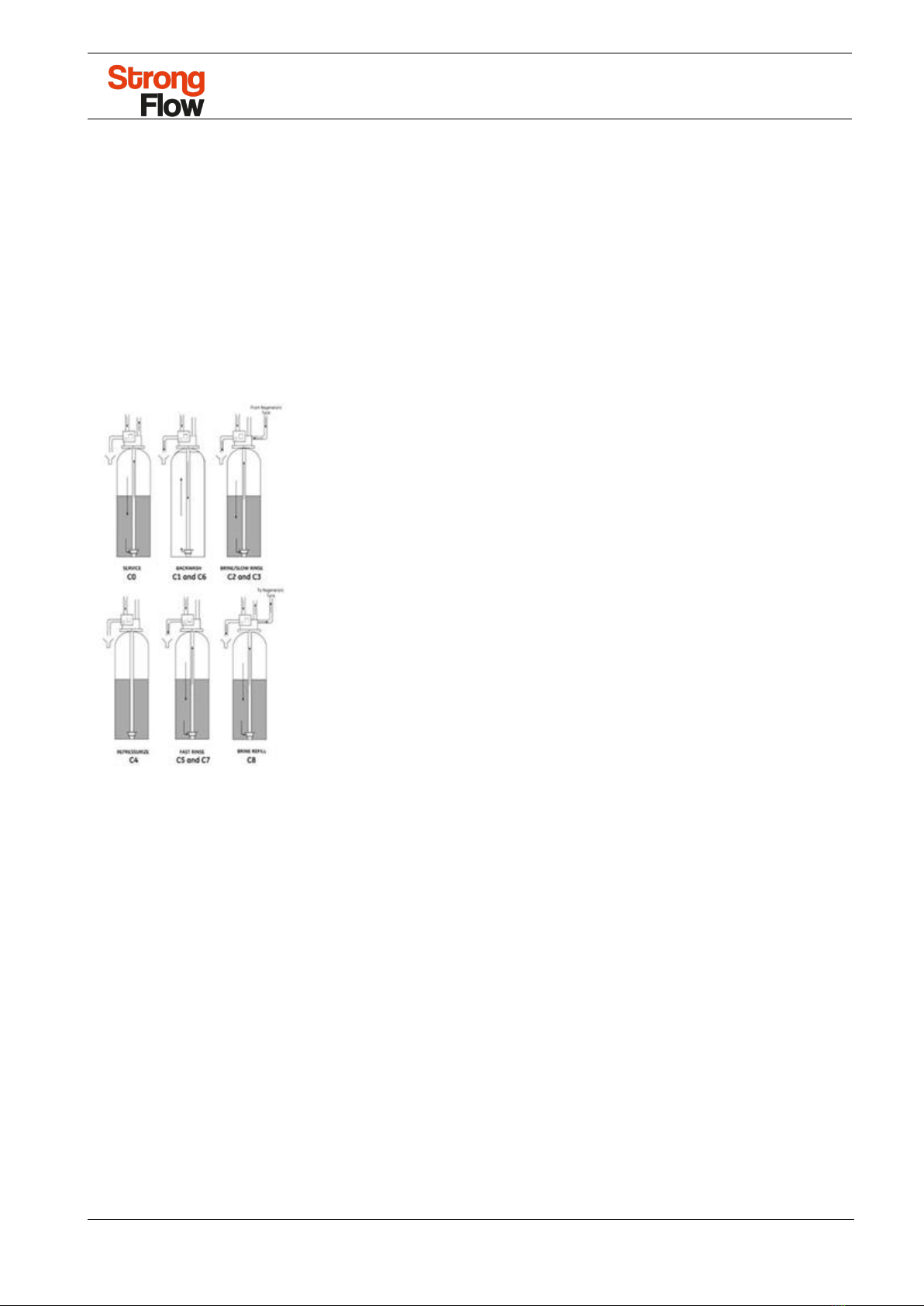
4.4.1 Regeneration modes
Below is described the regeneration cycles of automatic valve that is used in AG-CAB filters.
C0 = Normal filtering stage (not shown)
C1 = Regeneration back wash
C2 = Suction of the brine
C3 = Slow flushing
C4 = Pressurizing / prepared
C5 = Quick flushing
C6 = Backwash 2 (only in valve 255)
C7= Quick flush 2 (only in valve 255)
C8= Fill of brine tank with water
Picture 8. regeneration cycles
4.4.2 Manual regeneration
Manual regeneration can be done with two ways:
Option 1. Press the REGENERATE button shortly. Regeneration symbol starts blinking on the
screen. Valve executes additional regeneration cycle on the pre-set time (2:00 as standard).
Option 2. Press the REGENERATE button for five seconds and the regeneration cycle starts
immediately.

Operating and maintenance
instructions
AG-250/330 water softeners
Sivu 16/22
StrongFlow Oy
Tel. +358 20 730 1820
Domicile: Kaarina
Ahokylänkatu 3
www.strongflow.fi
Business ID: 2024125-8
FI-20780 Kaarina
VAT no: FI25511181
5. START-UP OF THE FILTER AND VALVE
The actual start-up of filter can be made after filter is in place and controller is programmed. Please
see the following instructions.
1. Remove the cover of valve.
2. Make sure that water inlet and outlet valves (and by-pass valve if exists) are closed
3. Press the Regenerate-button for five seconds to start the regeneration manually –camshaft
now turns to regeneration position C1.
4. Remove the air from filter. When filter is in stage C1 open the inlet valve partially. Do not
open the inlet valve fully to prevent that filtering resin goes to automatic valve.
5. When the filter is full of water the water starts to flow slowly to drain. Inlet valve can now
be fully opened. Let the water flow to drain until it becomes clear.
6. Fill the brine tank (start-up fill). First the brine tank is filled with water about 10 cm from the
bottom of the brine tank. Then insert about 50-75 kg of clean regeneration salt to brine tank.
There needs to be enough salt that the brine becomes saturated (salt is filled at least 30 cm
from bottom of the tank). Then fill some 15 l of additional water to brine tank.
7. Make sure that the water inlet valve is now fully open.
8. Press the SET and arrow UP buttons at the same time to set the valve to next stage C2. Press
the SET and arrow UP buttons again at the same time to set the valve to next stage C3.
Repeat this until valve is in stage C8.
9. Let the water to flow to brine tank.
10. Press once more SET and UP arrow buttons at the same time to set the system to C0 stage
(C0 not shown in the controller screen).

Operating and maintenance
instructions
AG-250/330 water softeners
Sivu 17/22
StrongFlow Oy
Tel. +358 20 730 1820
Domicile: Kaarina
Ahokylänkatu 3
www.strongflow.fi
Business ID: 2024125-8
FI-20780 Kaarina
VAT no: FI25511181
6. MAINTENANCE AND TROUBLESHOOTING
6.1 Cleaning the automatic valve filter screen/net
Within normal use it is enough if automatic valves filter screen/net is cleaned once or twice a year.
Screen/net is located on the left side of the valve.
6.2 Changing the resin
Please see following instruction for changing the filtering resin.
1. Close the inlet and outlet valves.
2. Start the regeneration cycle manually (see chapter 4.4.2, page 15) and wait until valve is in
backwash stage C1 - the filter is now unpressurized.
3. Remover the electric power plug from valve and open/remove the filters water line
connections.
4. Remove the automatic valve (twist the valve - right handed thread) and plug the diffusor
upper end of tube.
5. Hose water inside the tank so the resin starts to flow out together with water. Remove the
diffusor tube and continue until all resin is removed from the tank. Take care of the
disposal of used resin according to your local instructions (e.g. polymer-based can be
treated like other plastic waste).
6. Fill the tank with new resin as instructed in chapter 2.2 (page 5).
Operating and maintenance
instructions
AG-250/330 water softeners
Sivu 18/22
StrongFlow Oy
Tel. +358 20 730 1820
Domicile: Kaarina
Ahokylänkatu 3
www.strongflow.fi
Business ID: 2024125-8
FI-20780 Kaarina
VAT no: FI25511181
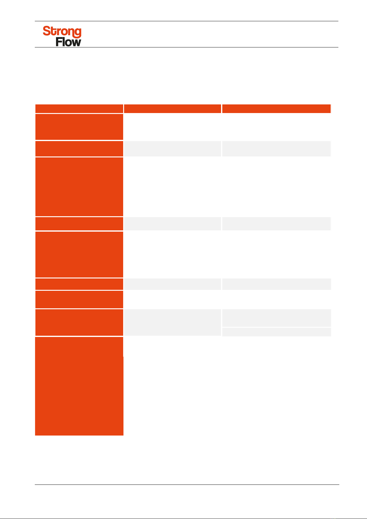
6.3 Possible problems and causes
Problem Possible cause Solution
a. Uncontrolled brine refill flow rate a. Remove brine control to clean ball and seat
b. Air leak in brine to air check b. Check al connections in brine line for leaks.
Refer to instructions.
c. Drain controlclogged with resin or other debris c. Clean drain control
Flowing or dripping water at a. Valve stem return spring weak a. Replace spring. (Contact dealer)
drain or brine line after regeneration b. Debris preventing valve disc from closing b. Remove debris
a. Low water pressure a. Make correct setting according to instructions.
b. Restricted drain line b. Remove restriction.
c. Injector plugged c. Clean injector and screen.
d. Injector defective d. Replace injector and cap. (Contact dealer)
e. Valve disc 2 and/or 3 not closed. e. Remove foreign matter from disc and check
disc for closing by pushing in on stem.
Replace if needed. (Contact dealer)
f. Air check valve prematurely closed f. Put control momentarily into brine refill, C8.
Replace or repair air check if needed
a. AC adapter or motor not connected a. Connect power
b. Defective adapter or motor b. Replace adapter/motor. (Connect dealer.)
Brine tank overflow
Control will not draw brine
Control will not regenerate automatically
a. Improper regeneration a. Repeat regeneration after making certain
correct salt dosage was set.
b. No salt in regenerant tank b. Add salt
No conditioned water after c. Injector or screen plugged c. Clean injector and screen.
regeneration d. Air check valve closes prematurely d. Put control momentarily in brine/slow rinse, C2
Replace or repair air check if needed
(Contact dealer.)
Water taste salty Regeneration does not work normally Check brine draw and time of regeneration.
Control power has been connected and the
controlis not sure of the estate of the operation.
Disconnect and reconnect the power. If problem
persists, obtain the appropriate controller or AC
adapter for either 50 or 60 Hz power.
a. Controller does not know the position of the a. Wait for two minutes fot the controller to return to
camshaft. Camshaft should be rotating to find home position. The hourglass should be flashing on
home position. the display indicating the motor is running.
b. Check that motor and optical sensor is connected.
Verify that motor wire harness is connected to motor
and controller module. Verify that motor gear has
engaged can gear. If everything is connected try
replacing in this order:
wire harness, motor, optical sensot, controller.
c. Camshaft is turning for more than five c. Verify that optical sensor is in place and connected
minutes to find position to wire. Verify that camshaft is connected appropriately.
Verify that no dirt or rubbish is clogging any of the cam
slots. If motor continues to rotate indefinitely, replace
the following components in this order:
wire harness, motor, optical sensot, controller.
ERR 2 is displayed
b. Camshaft is not turning during ERR3 display.
ERR 3 is displayed
Control power does not match 50 or 60 Hz
Press the UP arrow and the control should reset.
ERR 1 is displayed
Operating and maintenance
instructions
AG-250/330 water softeners
Sivu 19/22
StrongFlow Oy
Tel. +358 20 730 1820
Domicile: Kaarina
Ahokylänkatu 3
www.strongflow.fi
Business ID: 2024125-8
FI-20780 Kaarina
VAT no: FI25511181
7. ATTACHMENTS
Attachment 1: Automatic valve configuration
Operating and maintenance
instructions
AG-250/330 water softeners
Sivu 20/22
StrongFlow Oy
Tel. +358 20 730 1820
Domicile: Kaarina
Ahokylänkatu 3
www.strongflow.fi
Business ID: 2024125-8
FI-20780 Kaarina
VAT no: FI25511181
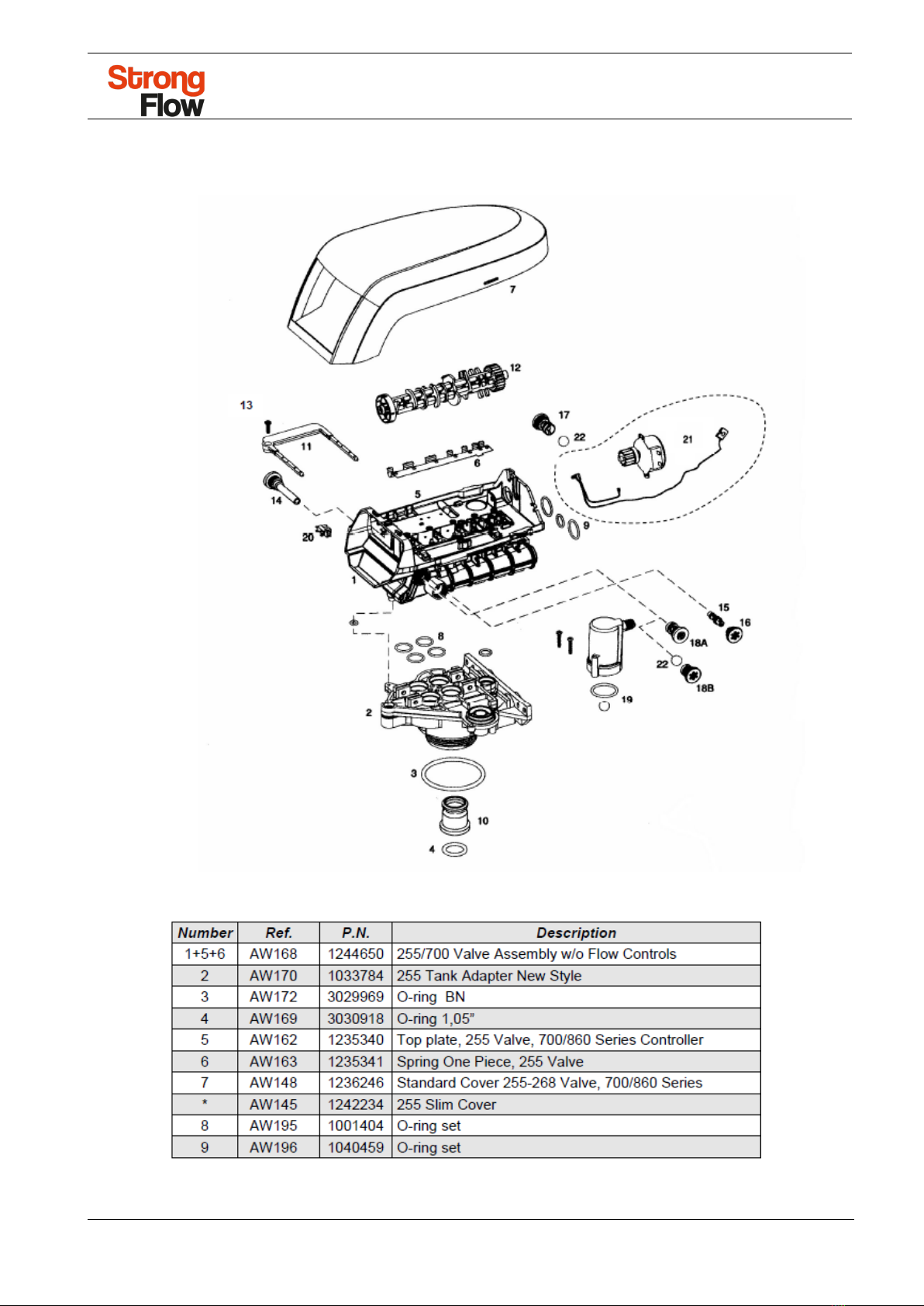
Attachment 2: Exploded view and spare part list
This manual suits for next models
2
Table of contents
Popular Water Dispenser manuals by other brands

Whirlpool
Whirlpool WHES48 Installation and operation manual

Asset
Asset ATLANTIS 60 Installation, user and maintenance manual

Pentair
Pentair FLECK 5600SXT Service manual

Rain Tree
Rain Tree BioSand Filter user manual

Oster
Oster Chill & Filter Powered Water Dispenser instruction manual

Puretec
Puretec SOL-2CI Series user guide

Hague
Hague MAXIMIZER 7180 Owner's manual and installation guide

H2O
H2O H2O-56SE-R-32 quick start guide

Water Depot
Water Depot ECONO Series owner's manual

Canature WaterGroup
Canature WaterGroup 85HE owner's manual

Bradley
Bradley Terreon TDB3108 Installation

Follett
Follett Symphony Plus installation instructions


