Strongman Tools Telford User manual
Version 1
1
INSTALLATION MANUAL& OPERATION
INSTRUCTIONS
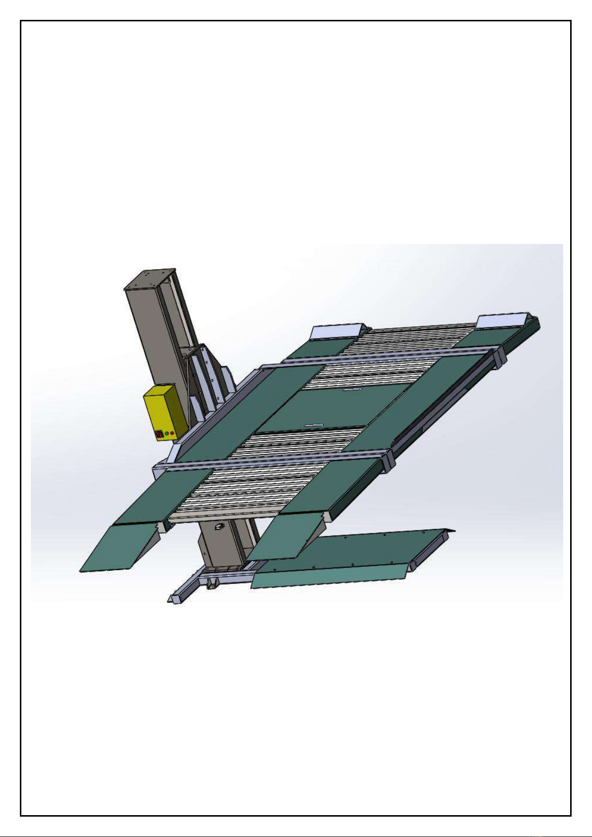
SINGLE POST CAR PARKING LIFT

Version 1
2
Date: 5/06/2018
TABLE OF CONTENTS
CHAPTER 1: USER’S RECORD 3
CHAPTER 2: INTRODUCTION 4
CHAPTER 3: SAFETY INSTRUCTIONS 5
CHAPTER 4: DESCRIPTION AND TECHNICAL DATA 9
CHAPTER 5: INSTALLATION INSTRUCTIONS 12
CHAPTER 6: INSTALLATION STEPS 17
CHAPTER 7: OPERATION INSTRUCTIONS 30
CHAPTER 8: MAINTENANCE 34
CHAPTER 9: ELECTRIC & HYDRAULIC DIAGRAMS 36
CHAPTER 10: TROUBLE SHOOTING 41
CHAPTER 11: LIMITED WARRANTY 43
NOTES 44

Version 1
3
CHAPTER 1: USER’S RECORD
RECORD BELOW INFORMATION WHICH LOCATED ON THE NAME PLATE
MODEL NO ____________________________
SERIAL NO ____________________________
CUSTOMER ____________________________
DATE OF INSTALLATION _________________
WE HEREBY DECLARED THAT THE ABOVE MENTIONED MACHINE HAS BEEN INSTALLED
CORRECTLY. ALL FUNCTIONS HAVE BEEN CHECKED AS WELL AS CORRECT OPERATING
OF ALL SAFETY DEVICES. WE CONSIDER THEREFORE THE MACHINE WORK IN GOOD
CONDITION.
Date of Installation The authorized technician
---------------------------- ------------------------------------
The customer
---------------------------------
(READ THIS MANUAL COMPLETELY AND PAY MORE ATTENTION TO THE INSTRUCTIONS BEFORE INSTALLING)

Version 1
4
CHAPTER
2:
INTRODUCTION
This
Manual
has
been
made
to
supply
the
owner
as
well
the
user
with
the
basic
instructions
for
installation
and
a
correct
use
of
the
Single
post
car
parking
lift
.
Read this guide carefully before using the lift and follow the instructions given by this guide to grant
it a correct function, efficiency and a long service life.
Single
post
car
parking
lift is
dependant
parking
type
where
it
requires
valet
to
remove
lower
car
away
before
lowering
the
platform.
This lift is suitable for residential parking purposes. The platform moves only vertically, so that the
users have to clear the ground level to get the higher level car down. It is hydraulic driven Type that
lifted directly by cylinder with chain connected to carriage.
This is electro-hydraulic lift used ONLY for motor vehicle parking.
The product designed according to the EN 1493:2010 and EN 14010:2003+A1:2009.
Reference of Directive Machine: 2006/42/EC.
Working Principle:
1. When operating the unit and pushing UP Button, the hydraulic power unit will be electrically
activated to pump hydraulic oil from tank to hydraulic oil cylinder.
2. The hydraulic cylinder will pull upwards the steel chain which is connected to the carriage.
3. The carriage will lift the platform as both of them are connected with bolts.
4. Once reaching pr-determined lifting height, the carriage will touch the limit switch and stop
the hydraulic motor.
5. The ground floor under the platform is free for parking lower car.

Version 1
5
CHAPTER 3: SAFETY INSTRUCTIONS
1. Read and understand all safety warning procedures before operating the parking lift.
2. Do not install the parking lift on any asphalt surface.
3. This parking lift is designed for parking motor vehicles that weighs within its max lifting
capacity.
4. Exceeding the maximum lifting weight will cause grave damage to the lift and DANGEROUS
INJURIES for the persons.
5. This parking lift, in its standard version, is not designed for outdoor use.
6. This parking lift is not designed to be used as car service lift to do any maintenance for the
car on platform.
7. The manufacturer doesn’t bear any responsibility for any accidents or damage might
happen to the cars or/and persons due to misuse of the lift.
8. Keep hands and feet away from any moving parts. Keep feet clear of parking lift when
lowering.
9. The parking lift MUST only be used by qualified staff, properly trained for such work.
10.During installation, do not wear unfit clothes, large cloves, ties, etc, which could get caught
by moving parts of the machine.
11. The parking lift surrounding area must be free from people or objects which could be a
danger for lifting operations.
12.Use suitable handling and lifting tools/equipment such as crane, forklift, and pallet lift during
off-loading of the packages and during installation of different parts.
13.Always insure the safety devices are engaged before any attempt to work on or near
vehicle.

Version 1
6
14.The parking lift is only designed to park the entire body of vehicle, having maximum weight
not more than the lift capacity.
15.The vehicle must be centered and positioned in a stable correct way with respect to the
platform and following the instructions given by manufacturer.
16.Make sure that the lift and its devices are working correctly, according to the specific
instructions for maintenance.
17.Do not modify the parking lift without manufacturer’s written approval.
18.If the parking lift will not be used for a long period, proceed as follows:
a. Disconnect the energy source.
b. Empty the oil from the Hydraulic unit tank.
c. Grease the moving parts which might be damaged by dust or drying out.
19.Only Authorized personnel are allowed to operate the control box. Only person with
qualification for repairing electrical appliances could open control box.
20.Control box is allowed to open only after power is cut off.
21.Installation technicians should be healthy, well trained and qualified to carry on the
installation with experience for both mechanical &electrical work.
22.The car must be parked at the right direction.(See below Fig.1)

Version 1
7
WARNING SIGNS

Version 1
8
Fig.2
Fig.3

Version 1
9
CHAPTER 4: DESCRIPTION AND TECHNICAL DATA
4.1 OVERALL DESCRIPTION
1
. Unit Base
2. Cover of base
3. Carriage
4. Post
5. Support beam
6. Platform (3 pcs)
7. Ramp
8. Wave plate
9. Stopper
10. Hydraulic power unit
motor
11. Oil Tank
12. Stand of control
box
13. Control
box(could be
fixed on the post)
Version 1
10
4.2 TECHNICAL DATA
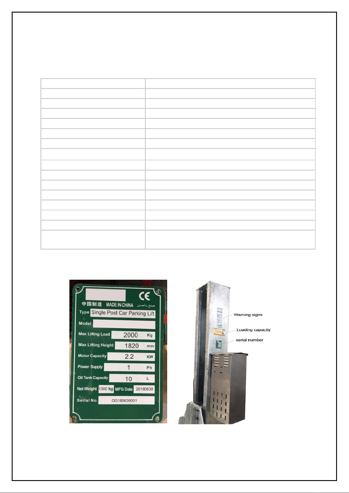
4.3 Identification Plate with Serial Number:
Fig.4 Fig.5
Manufacturer Strongman Tools Ltd
Machine Type Single Post Car Parking Lift – Hydraulic driven
Model NO. Telford - Single Post
Max Lifting Capacity 2000 Kg
Max Lifting Height 1820mm
Max dimension of vehicle 5000*1850*1550mm
Max weight of vehicle 2000 Kg
Lock Release Type Electric lock release
Outline Dimension 3945x 2631x 2479 mm
Unit Weight 1300 Kg
Parking Width 2000mm
Rise/Drop Time 60 S/50 S
Power Supply/Motor Capacity 220V/ 1Ph/ 50Hz. - 2.2 KW
Run Way & Ramps Diamond Steel Plates
Noise Level ≤85dB
Platform – Middle Diamond Steel Plates and removable Corrugated
Galvanized Steel Plates
Version 1
11
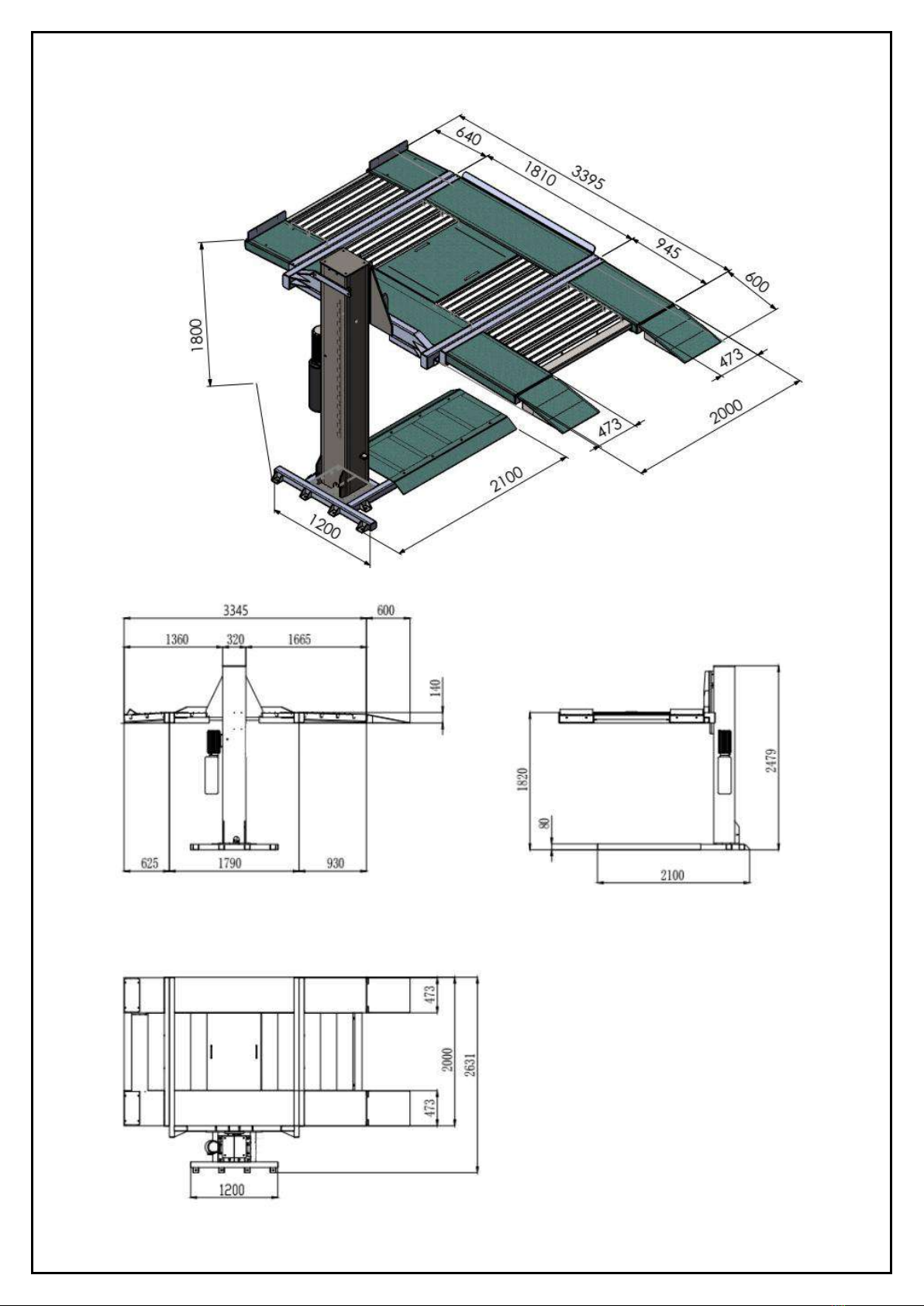
4.4 LiftDimensions
12
Version
1
CHAPTER
5:
INSTALLATION
INSTRUCTIONS
Strongman Tools Ltd Equipment,
ensuring
our
customers’
safety
is
our
primary
concern. Our
car
parking
lift
was
designed
and
built
with
safety.
However,
safety
relies
on
proper
installation
and
training.
Prepare
for
a
successful
installation
by
making
sure
your
floor
meets
specific
requirements.
Installation
technicians
should
be
healthy,
well
trained
and
qualified
to
carry
on
the
installation
with
experience
for
both
mechanical
&electrical
work.
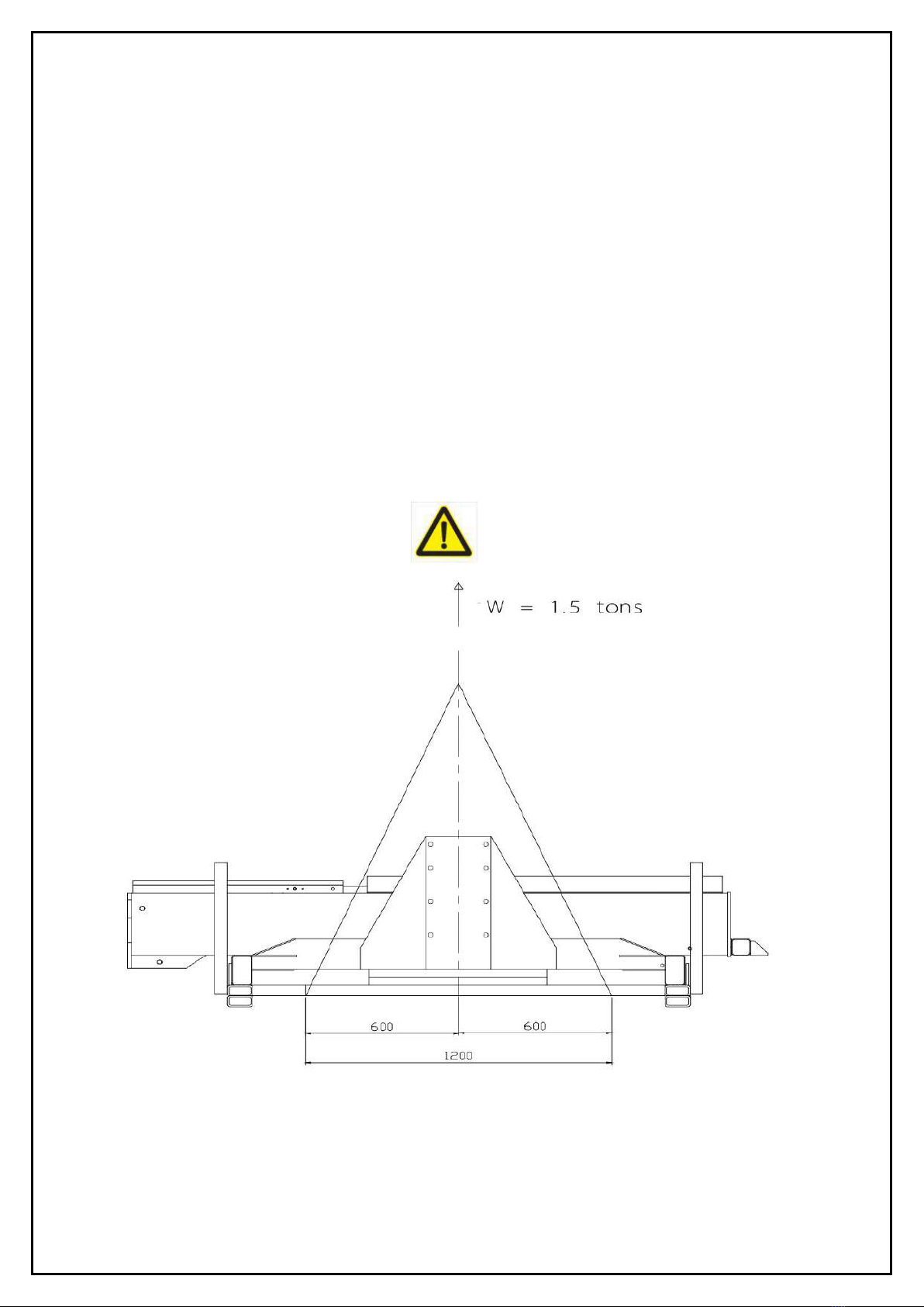
Use
hoist
/
crane
with
suitable
steel
chain
or
woven
belt
to
lift
he
package
to
the
place
you
need
to
install.
The
lifting
capacity
of
the
hoist
must
be
more
than
1.5
Ton.
Fig.6
Version 1
13
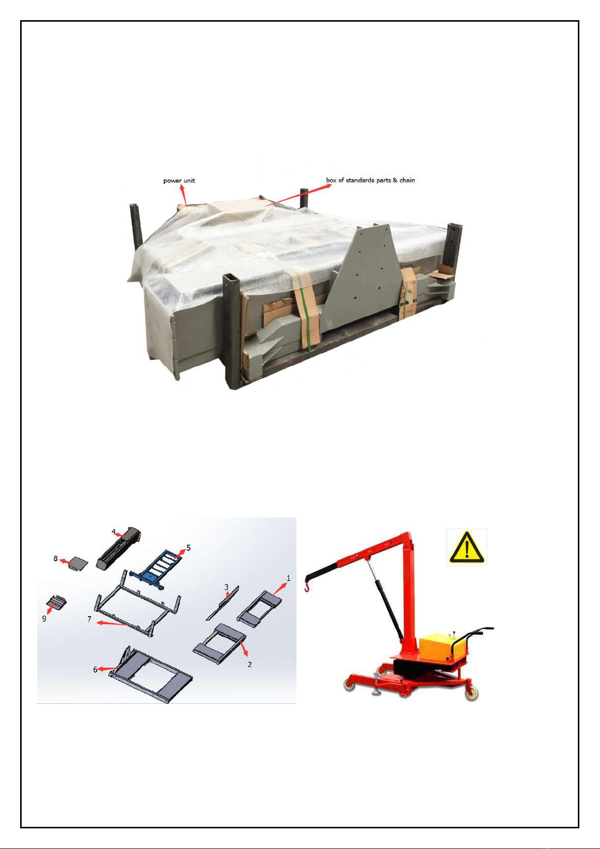
5.1 Unpacking the package
Check the package and off-load the contents near the installation place.
Fig. 7
The hydraulic power unit box and standard parts & chains box are light, could be carried by hand.
Then take out steel parts one by one using suitable lifting hoist (Fig. 9 is an example of hoist).
Fig. 8 Fig. 9

Version 1
14
Parts need crane or hoist to carry during off-loading the package for installing the lift
Description Weight (kg) Carrying Method
1 Runway platform (at stopper side) 85
By Crane or hoist
2 Runway platform (at ramp side) 105
3 Cover of base 48
4 Post and Carriage 325
5 Base 103
6 Mid platform 364
7 Steel plate for packaging 128
Parts with weight less than 20kg
8 ramps
Human handling
9 Power unit
10 chains
11 Standard parts
5.2 SITE SELECTION:
Before installing your car parking lift, check the following:
Lift Location: Always use architect’s plans when available.
Check layout dimension against floor plan requirements making sure adequate space is
available. Your lift requires a 220v, 30amp, single phase, grounded electrical source. There
should be room enough to operate the lift in a safe manner and without restrictions.
Space Required: Please refer to the drawing for detailed installation size.
Overhead Area: The area where the lift will be located should be free of overhead obstructions
such as heaters, building supports, electrical lines, doors, lights, etc.
Floor Area: Visually inspect the site where the lift is to be installed and check for cracked or
defective concrete.

Version 1
15
5.3 FLOOR REQUIREMENTS:
A leveled floor is strongly suggested for proper installation and balance lifting. Small differences
in floor slopes may be compensated by proper shims. If a floor is of questionable slope,
consider the possibility of pouring a new level concrete slab.
DO NOT install car lift on any asphalt surface or any surface other than concrete.
DO NOT install car lift on expansion seams or on cracked or defective concrete.
DO NOT install car lift on a second/elevated floor without consulting building architect first.
DO NOT install car lift outdoor as it’s not designed for outdoor conditions.
New concrete must be adequately cured for at least 30 days.
All models MUST be installed on 3,000 PSI reinforced concrete slab only.
New Poured Concrete slab Specifications: Minimum 200 mm thickness.
Old ,unleveled or damaged Concrete slab Specifications:
In this case you can cut out a 1m x 1m square form the old slab, and pour new concrete to a depth
of about 300mm. You can then tie this new section of slab back into the existing slab with Rotary
Hammer Drill drilled in. Do it under all car lift posts.
Specifications of concrete must be adhered to. Failure to do so could cause car lift failure resulting
in personal injury or death. The floor strength should be suitable to carry the weight of the car lift
plus 2 cars, one on the ground floor and one on the platform.
5.4 Other environment requirements
Temperature required: -30 ºC to 45 ºC
Air humidity:≤80%
Altitude: ≤2000 m
5.5 TOOLS AND EQUIPMENT NEEDED:
Appropriate lifting equipment such as forklift or Hoist.
Rando HD 46 or other good quality garage hydraulic oil.
Chalk line and measure tape.
Rotary Hammer Drill with 3/4’’ drill bit.
Sockets and Open wrench set.
Vise Grips.
Lithium lubricating grease

Version 1
16
5.6 PARTS LIST:
Main Parts list
Item Size (mm) Qty Item Size Qty
Stop plate 470*100*40 2 Oil Tank 10 L 1
Base cover 1420*830 1 Steel wire rope 1
Post 230*290*320 1 Chain Lh12461 1
Ramp 600*470 2 Base plate 1
Gusset plate 1040*745 1 Hydraulic Cylinder 1
Wave plate 1040*224 8 Steel wire rope 1
Middle platform
runway
1650*473 2 carriage 1
Platform Runway (At
Stop plate side)
555*473 2 Hydraulic Power
Unit
1
Platform Runway (At
Ramp side)
860*473 2 Operation Panel 1
Oil Hose 1
Standard Parts List
Item Size Qty Item Size Qty
Hex bolt, flat washer ,
spring washer
M8*30 4 Nut M12 1
Hex bolt, flat washer,
spring washer
M18*45 18 Chain wheel Φ110 1
Bolt M5*15 4 Roller on carriage 4
Bolt M6*20 1 Oil bearing 42*38*50 5
Hex bolt, flat washer,
spring washer
M12*35 4 Limit switch 1
Bolt M6*25 1 Limit switch cable 2*0.5 1.5 m
Countersunk bolt M6*15 1 Flat washer 16 2
Countersunk bolt M10*10 1 Split cotter 2.5 4
Hex bolt ,flat washer ,
spring washer
M14*30 4 Elastic cylindrical
pin
φ3*20 2
Hex bolt M5*30 4 Flat washer 12 1
Countersunk bolt M10*15 6 Sliding block 8
Anchor Bolt M18*220 12 Electromagnetic 1
Bolt M4*20 4 Cable 1
Expansion Anchor
Bolt
M20*180 8 Hose 2-JIC1/2 1
Elbow ZG1/4-JIC1/2 1

Version 1
17
5.7
BEFORE
INSTALLATION
1.Identify
the
packaging
components
and
check
for
missing
parts.
Contact
Strongman
if
shortage
discovered.
2.Installation,
adjusting
and
testing
operations
are
to
be
performed
by
qualified
staff
only.
3.The
lift
must
be
installed
on
a
leveled
concrete
floor,
having
minimum
thickness
of
150
mm
and
an
extension
of
at
least
1500
mm
from
anchoring
points.
4.The
lift
installation
concrete
surface
must
be
relatively
smooth,
leveled
in
all
directions
5.After
unloading
the
package,
place
it
near
the
intended
installation
location.
6.Dismantle
the
steel
parts
of
the
lift
from
the
package.
7.Remove
the
packing
materials
(steel
brackets,
cartoons,
etc)
from
the
installation
site.
CHAPTER 6: INSTALLATION STEPS
6.1 : DETERMINE LOCATION AND MARK WITH CHALK ON THE FLOOR
1.Determine the location for installing the parking unit considering all safety instructions.
2.Place the base on the floor and confirm its location before fixing to the floor.
3.Mark base outline with chalk on floor to ensure no displacement occurs during installation.
Fig 10

Version 1
18
6.2 INSTALL THE BASE ON THE FLOOR.
Before this step, carry the base by crane or hoist to installation site as it is heavy.
1. Drill each anchor hole in the concrete using a rotary hammer drill. To assure full holding power, do
not oversize the hole or allow drill to wobble. (Fig.11)
3. After drilling, remove dust thoroughly from each hole and make certain that the base remains
aligned with the chalk line during this process.
4. If shimming is required, insert the shims with selected thickness as necessary under the base plate
anchor bolts so that when the anchor bolts are tightened, the base will be horizontal. (Fig12).
5. With the shims and anchor bolts in place, tighten by securing the nut to the base then turning2-3 full
turns clockwise. DO NOT use an impact wrench for this procedure.

Version 1
19
Fig.11
Fig.12
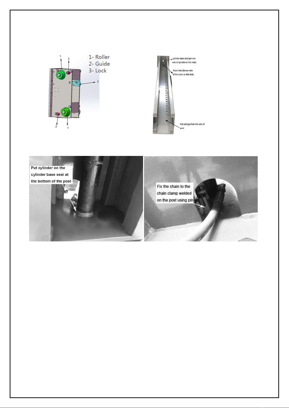
6.3: INSTALLATION OF CARRIAGE, CYLINDER & CHAIN INSIDE THE COLUMN (POST):
Carry carriage and post by
1. Insert the carriage (Fig 13) into the post from the top of the post (Fig 14).
2. Insert the chain pulley hole to the head of the cylinder.
3. Put the cylinder on the cylinder base seat at the bottom of the post (Fig 15).
4. Insert the chain inside the chain pulley and fix one side of the chain on the clamp behind the
cylinder base at the bottom of the post (Fig 16).
5. Fix the other side of the chain to the carriage using threaded connection rod M20 (Fig 17 & Fig 18).
6. Fix the cover on the top of the post using bolts M18 x 45.
Version 1
20
Fig.13 Fig.14
Fig15 Fig16
Table of contents


