Struers Discotom-6 User manual

Discotom-6
Instruction Manual
Manual No.: 15677001
Date of Release 09.09.2013

Discotom-6
Instruction Manual
Table of Contents Page
User’s Guide...............................................................1
Reference Guide.......................................................18
Quick Reference.......................................................31
Always state
Serial No and Voltage/frequency if you have technical questions or when ordering spare parts.
You will find the Ser
ial No. and Voltage on the type plate of the machine itself. We may also need the Date
and
Article No of the manual. This information is found on the front cover.
The following restrictions should be observed, as violation of the restrictions may cause ca
ncellation of
Struers legal obligations:
Instruction Manuals:
Struers Instruction Manual may only be used in connection with Struers equipment
covered by the Instruction Manual.
Service Manuals:
Struers Service Manual may only be used by a trained technician authorised by Struers.
The Service Manual may only be used in connection with Struers equipment covered by the Service Manual.
Struers assumes no responsibility for errors in the manual text/illustrations. The information in this manual is
subject to
change without notice. The manual may mention accessories or parts not included in the present
version of the equipment.
Original Instructions.
The contents of this manual are the property of Struers. Reproduction of any part of
this manual without the w
ritten permission of Struers is not allowed.
All rights reserved. © Struers
2013.
Struers A/S
Pederstrupvej 84
DK
-2750 Ballerup
Denmark
Telephone +45 44 600 800
Fax +45 44 600 801

Discotom-6
Instruction Manual
Discotom-6
Safety Precaution Sheet
To be read carefully
before use
1. The operator(s) should be fully instructed in the use of the machine and
its cut-off wheels according to the Instruction Manual and the
instructions for the cut-off wheels.
2. The machine must be placed on a safe and stable support table. All
safety functions and guards of the machine must be in working order.
3. Use only intact cut-off wheels. The cut-off wheels must be approved for
min. 50 m/s.
4. Observe the current safety regulations for handling, mixing, filling,
emptying and disposal of the additive for cooling fluid.
5. The workpiece must be securely fixed in the quick-clamping device or
similar. Large or sharp workpieces must be handled in a safe way.
6. The cutting handle should be lowered slowly and carefully, in order to
avoid breaking the cut-off wheel.
7. Struers recommends the use of an exhaust system as the materials
being cut may emit harmful gasses or dust.
8. The rubber curtains on the left hand side make it possible to cut long
workpieces with a height of up to 80mm.
9. Do not put your hand through the rubber curtain during operation of the
machine.
10. Use of safety goggles is recommended when using the flushing gun.
The equipment should only be used for its intended purpose and as detailed in the Instruction Manual.
The equipment is designed for use with consumables supplied by Struers. If subjected to misuse, improper
installation, alteration, neglect, accident or improper repair, Struers will accept no responsibility for
damage(s) to the user or the equipment.
Dismantling of any part of the equipment, during service or repair, should always be performed by a qualified
technician (electromechanical, electronic, mechanical, pneumatic, etc.)


Discotom-6
Instruction Manual
1
User’s Guide
Table of Contents Page
1.Getting Started
Checking the Contents.......................................................................2
Getting Acquainted with Discotom-6..................................................3
Discotom-6 Rear View..............................................................4
Noise Level ........................................................................................4
Power Supply.....................................................................................4
Direction of the Cut-off Wheel...................................................4
Connecting a Recirculation Cooling Unit............................................5
Connection to an External Exhaust System.......................................6
2.Basic Operations
Using the Controls..............................................................................7
Front Panel Controls of Discotom-6..........................................7
Front Panel Controls..........................................................................8
Cooling Valve Positions .....................................................................9
Cutting Position.........................................................................9
Cleaning Position......................................................................9
Light Diode and Beep Signals..........................................................10
Fitting or Changing the Cut-off Wheel..............................................11
Clamping the Workpiece..................................................................11
Starting/Stopping the Cutting Process.............................................12
Automatic Cutting (AUTO mode)............................................12
Manual Cutting........................................................................14
Combining Manual and Auto Operation...........................................15
Cleaning...........................................................................................15
Flushing the Cutting Chamber................................................15
3.Routine Maintenance
Daily Service ....................................................................................16
Weekly Service ................................................................................16
Monthly service ................................................................................16
Cleaning the Flushing Gun .....................................................16
Replacing the Cooling Water..................................................16
Yearly Service..................................................................................17
Inspection of Guard.................................................................17

Discotom-6
Instruction Manual
2
1. Getting Started
In the packing box you should find the following parts:
1 Fork spanner (24mm), for changing the cut-off wheel
1 Connector pipe for water outlet
3 Elbow pipes for water outlet
1 Outlet hose, 2 m
3 Hose clamps
1 Grease for Y-table spindle
1 Oil for maintenance of cutting table
1 Set of Instruction Manuals
Remove the screws underneath the pallet to free the Discotom-6.
Discotom-6 should be placed on a table that is able to carry a weight
of min. 140 kg.
Checking the Contents
Unpacking Discotom-6
Placing Discotom-6

Discotom-6
Instruction Manual
3
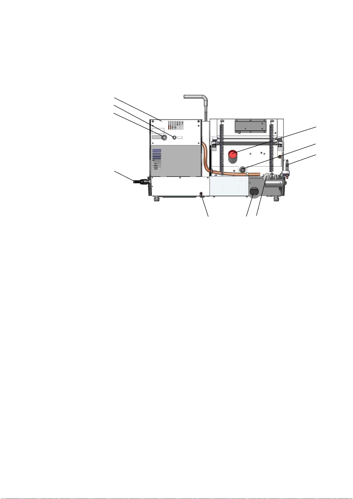
Take a moment to familiarise yourself with the location and names of
the Discotom-6 components.
Cutting handle
Protection guard, with window
Instrument panel
Emergency Stop
Flushing Gun
Cooling valve
Cutting table
Main power switch
Hours counter
Cut-off wheel locking handle
Getting Acquainted
with Discotom-6
(Right side view)
Discotom-6
Instruction Manual
4
Upper back plate
Cooli Unit connection
Electrical cable for power supply
Cut-off wheel locking handle
Exhaust hose
Water outlet to Flushing Gun
Flushing Gun
Drainage hose
Water outlet
Water inlet
Approx. 67 dB (A) measured at idle running, at a distance of
1.0 m/39.4” from the machine.
First check that the mains voltage corresponds to the voltage
stated on the type plate on the side of the machine.
Discotom-6 is factory mounted with an electric cable. Mount a
plug on the cable:
Black and brown = phase
Yellow/green = earth
Check that when the power is turned on, the cut-off wheel rotates in
the direction indicated by the moulded arrow in the guard of
Discotom-6. If the direction of rotation is incorrect, switch the two
phases.
Discotom-6 Rear View
Noise Level
Power Supply
Direction of the Cut-off Wheel
Discotom-6
Instruction Manual
5
To ensure optimal cooling, Discotom-6 can be fitted with a Cooli unit.
Cooling System 5 is a Cooli configuration designed for use with
Discotom.
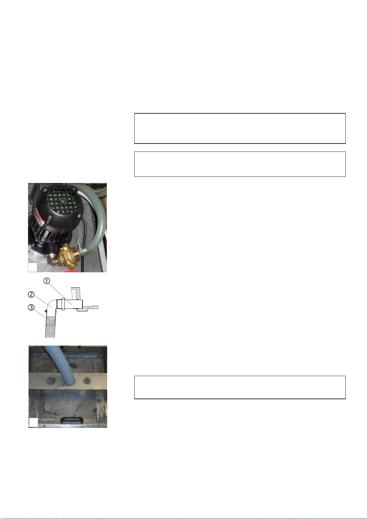
To connect the Discotom-6 to a Recirculation Cooling Unit:
Plug the Cooli control unit’s communication cable into the
Discotom’s control socket.
Connect the water inlet hose to the Cooli pump using the quick
coupling (A).
Connect the other end of the hose to the quick coupling of the
Discotom water inlet.
Insert the drain pipe in the water outlet on the back of
Discotom and mount the 90° elbow pipe . Lubricate the sealing
ring with grease or soap to facilitate insertion. (Use the other
elbow pipe if more suitable).
Strip the steel spring from approx. 3 cm of the outlet hose and
cut. Bend the cut end towards the centre of the hose. Mount the
outlet hose onto the elbow pipe and clamp the stripped
section using a hose clamp.
Check that the outlet hose slopes downwards when connected. If
necessary adjust the length of the hose.
Insert the open end of the hose into mounting hole in the bracket
on top of the Cooli filter unit (B).
Connect the cooling unit to the mains power supply.
Place the drainage hose in the tank of the Cooling Unit or lead to
drain.
Connecting a Recirculation
Cooling Unit
Note:
Cooling System 5 includes a static filter.
For intensive use, and for materials generating a lot of swarf, a bandfilter
such as Coolimat-200 is recommended.
Note
Before connecting the cooling unit to the Discotom, follow the instructions in
the Cooling Units Instruction Manual to prepare it for use.
IMPORTANT
Before connecting, check that the mains voltage corresponds to the voltage
stated on the type plate on the side of the machine.
Drainage Hose
A
B

Discotom-6
Instruction Manual
6
Struers recommends the use of an exhaust as workpieces may emit
harmful gasses or dust when cut. The exhaust system will also
reduce the level of water condensation on the sides of the protection
guard.
On the back of Discotom-6 you will find a joint for a 50 mm
(approx. 2") dia. exhaust hose.
Mount an exhaust hose from your local exhaust system onto the
joint.
Connection to an External
Exhaust System
Discotom-6
Instruction Manual
7
2. Basic Operations
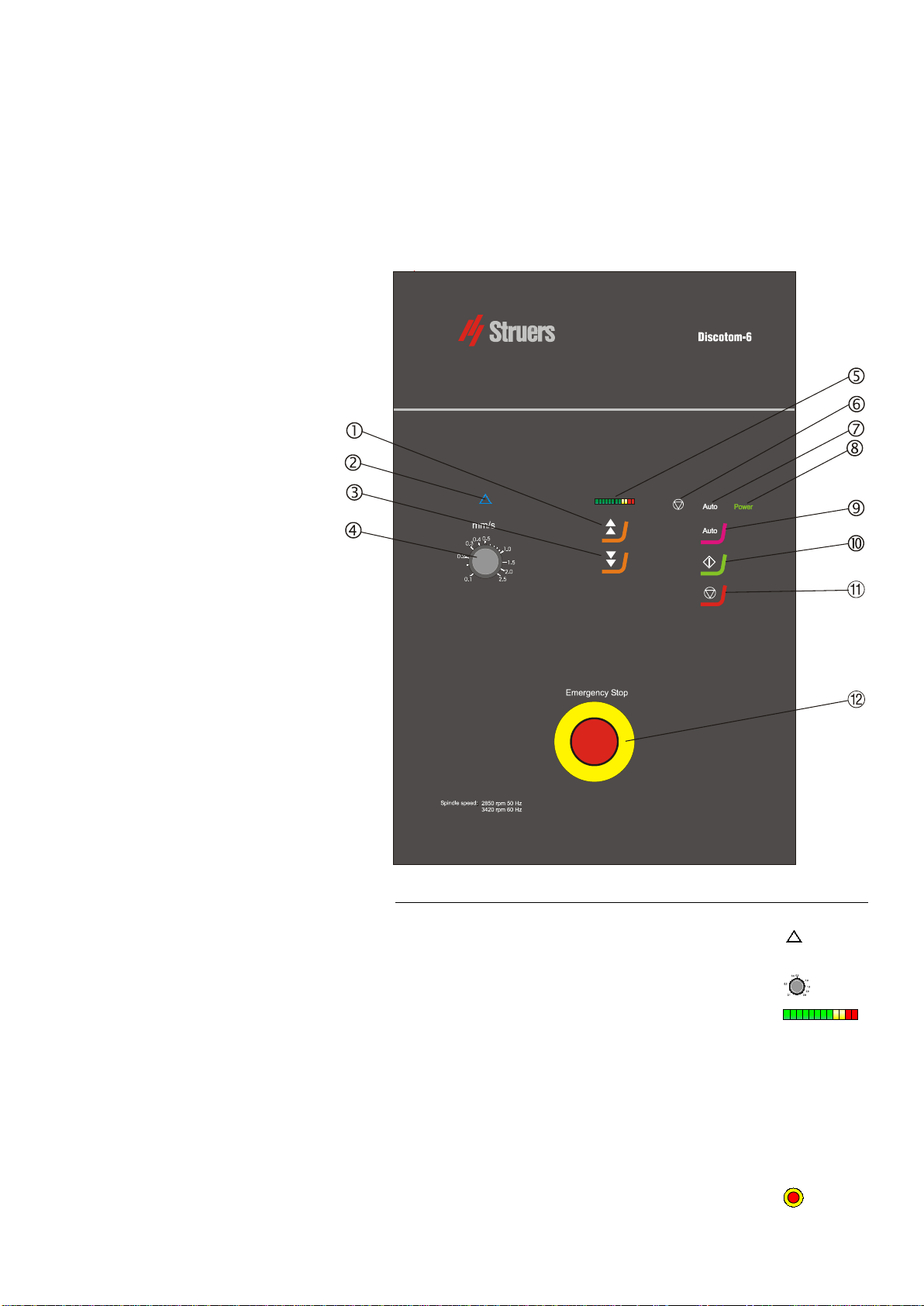
Control name Symbol
Forwards button................................................................
Feed Speed Reduced indicator light.................................
Backwards button.............................................................
Feed Speed potentiometer...............................................
Load bar...........................................................................
Emergency stop/overload
indicator light ....................................................................
Auto mode indicator light..................................................Auto
Power indicator light.........................................................Power
Auto key ...........................................................................Auto
Start key ..........................................................................
Stop key ...........................................................................
Emergency stop button.....................................................
Using the Controls
Front Panel Controls
of Discotom-6
Discotom-6
Instruction Manual
8
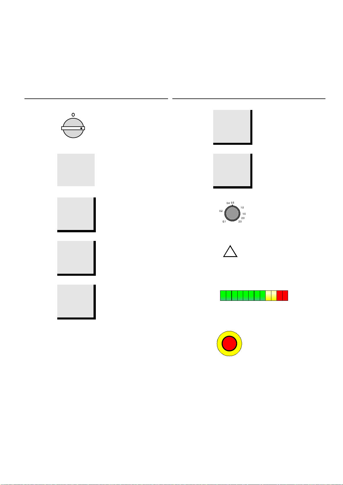
Name Key Function
Name Key Function
MAIN
SWITCH
The main power switch is
located on the right hand
side of Discotom-6. Turn
clockwise to switch on the
power.
FORWARDS Moves cutting table forward.
POWER
INDICATOR
Power Lights when main power is
switched on.
BACKWARDS Moves cutting table
backwards.
START Starts the machine. The cut-
off wheel starts rotating and
the cooling water is turned
on.
FEED SPEED
Regulates the feed speed of
the cutting table. The speed
can be set from 0.1-2.5
mm/sec.
STOP Stops the machine. The cut-
off wheel stops rotating and
the cooling water is turned
off.
FEED SPEED
REDUCED
Lights when the feed speed
has been set too high and is
reduced by the machine.
AUTO
Auto Select or deselect automatic
cutting mode
LOAD BAR
Reflects the present motor load status.
AUTO
INDICATOR
Auto
Lights when automatic
cutting mode selected.
EMERGENCY
STOP
Push the red button to stop.
Pull the red button to release.
EMERG. STOP
OVERLOAD
Lights when emergency stop
has been pressed or the
cutting motor is overloaded.
Front Panel Controls
Discotom-6
Instruction Manual
9
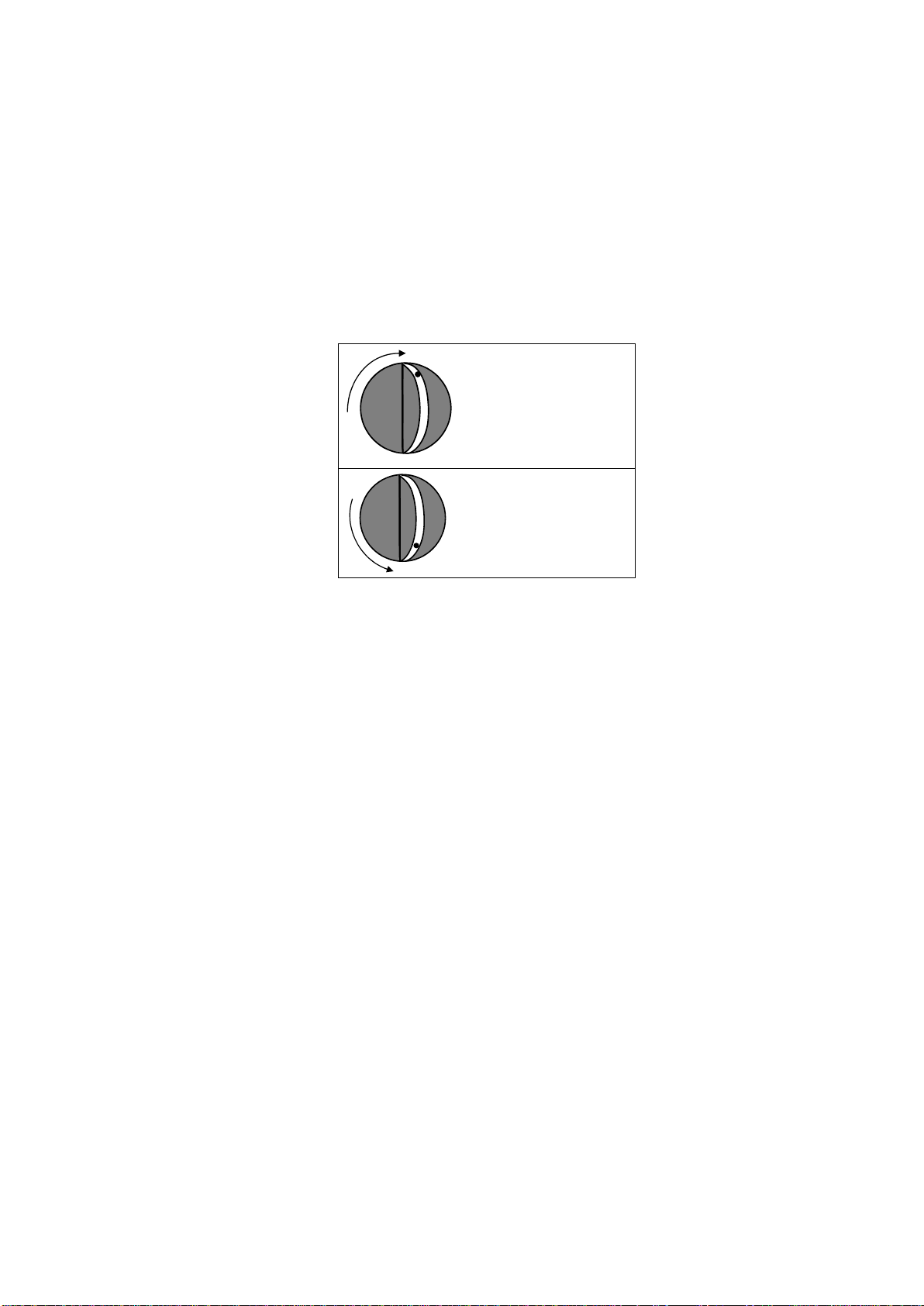
The flushing gun, and a valve for cooling and cleaning, are located
on the left hand side of the cutting machine.
During cutting the valve is turned clockwise (mark at the top) and the
water is directed to cool the cut-off wheel. For cleaning the valve is
turned counter-clockwise (mark at the bottom) to flush the cutting
chamber.
Cooling Valve Positions
Turn the knob clockwise
to vertical position to
cool the cut-off wheel.
Turn the knob counter-
clockwise to vertical
position for flushing the
cutting chamber.
Cutting Position
Cleaning Position
Discotom-6
Instruction Manual
10
Discotom-6 is provided with various light diodes indicating the status
of the machine. Beep signals will sound if a key is pressed when the
function cannot be activated.
Status
Indication
Comments
Green POWER indicator on The main power switch has been
turned on.
White AUTO indicator on
AUTO mode is active.
Beep signal You pressed AUTO, START ,
FORWARDS or BACKWARDS
while the motor was running.
2 long Beep signals You pressed START while the
protection guard was open.
3 long Beep signals You pressed START for cutting
while cooling valve isn’t in cutting
position.
Turn cooling valve to cutting position.
Red
indicator on The emergency stop has been
pressed. Release the emergency stop to shut off
the indicator.
Red
indicator on and
beep signal The emergency stop has been
pressed and you tried to press
another key.
Yellow FEED SPEED
REDUCED indicator blinking
In AUTO mode: the feed speed is
too high. The machine automatically turns the feed
speed down.
An AUTO cut has finished. Feed
speed reduced.
Turn the feed speed down or press any
key.
Red
and yellow FEED
SPEED REDUCED indicators
blinking
Cutting in AUTO mode not possible
as the cutting table does not move. Press any key to stop the indicators.
Material may be too hard for the cut-off
wheel chosen or cutting table may be
jammed. See Trouble Shooting section at
back of manual.
Red
indicator and 1 red
cell on LOAD BAR Pump motor overloaded. Stop the machine. Push the red button on
the back of the machine to reset the
safety cut-out.
Red
indicator and 2 red
cells on LOAD BAR
Main motor overloaded. Process
halted. The indicators will disappear when the
motor has cooled down.
Red
indicator, 2 red cells
on LOAD BAR and beep
signal
You tried to press a key before the motor
had cooled down.
Light Diode and Beep Signals

Discotom-6
Instruction Manual
11
Note: The spindle for Discotom-6 is left-hand threaded. If Discotom-6
has been used for manual cutting, fasten the cutting handle with the
black handle at the right hand side of the machine before changing
the cut-off wheel.
Press and hold down the black locking knob on the right-hand
side of the cut-off wheel, turning the cut-off wheel until the
spindle lock clicks.
Remove the nut with a fork spanner. Remove the flange and the
old cut-off wheel.
Mount the new cut-off wheel.
Mount the flange and the nut. Tighten carefully and release the
locking knob.
Place the workpiece between the quick clamping devices and
the back stops.
Push the clamps towards the workpiece and lock the quick-
clamping devices with the locking handle.
Carefully close the protection guard.
Fitting or Changing the
Cut-off Wheel
IMPORTANT
Conventional cut-off wheels based on Al2O3/SiC abrasives should be placed
between two cardboard washers, to protect the cut-off wheel.
For maximum precision with diamond or CBN cut-off wheels, do not use
cardboard washers.
Clamping the Workpiece
IMPORTANT
The workpiece must be firmly held in the quick-clamping devices.

Discotom-6
Instruction Manual
12
When the machine is used in AUTO mode the cut-off wheel is
stationary and the cutting table moves. In MANUAL mode the cutting
table is stationary and the operator moves the cut-off wheel.
Clamp the workpiece.
Loosen the black handle situated on the right hand side of the
cutting chamber.
Lower the cut-off wheel by drawing the cutting handle
downwards until the cut-off wheel is positioned ready to cut the
workpiece. Fasten the black handle again.
Press FORWARDS to position the cutting table and the
workpiece just in front of the cut-off wheel.
Close the protection guard.
Set the desired feed speed
Press the AUTO mode key to select AUTO mode.
Press START to start the machine. The cut-off wheel starts
rotating and the cooling water is turned on. The cutting table
moves forward toward the cut-off wheel at the pre-set feed
speed.
If the machine has been stopped with the STOP key, the
cutting table will stay in position. To return the cutting table to its
start position press BACKWARDS once. Struers recommends
manually lifting the cut-off wheel away before the cutting table is
moved back. Please note that the protection guard has to be
closed in order to carry out this operation. If the protection guard
has been opened press and hold the BACKWARDS key to
move the cutting table to its start position.
If the cutting table reaches the back of the cutting chamber
during the cutting process, the cut-off wheel automatically stops
and the cutting table returns to its start position.
Starting/Stopping
the Cutting Process
Automatic Cutting
(AUTO mode)

Discotom-6
Instruction Manual
13
To set another stop position:
−Press FORWARDS to move the cutting table to the desired
position.
−Press and hold the STOP key and then press once on
FORWARDS to set this position as stop position Then
release the STOP key.
When the cutting table now reaches this position during
cutting, the cut-off wheel will stop and the cutting table will
return to its start position.
The set stop position will be cancelled when the power is
switched off.
Note: the cutting table can be positioned with FORWARDS and
BACKWARDS . When the keys are held down, the cutting table
moves with increased speed of 20 mm / sec.
If the feed speed is set too high, the yellow FEED SPEED
REDUCED indicator ( ) above the feed speed control flashes and
the feed speed is automatically reduced by 10%. Discotom-6 can
repeat this reduction up to 5 times.
Once the workpiece has been cut, the operator can reduce the feed
speed using the feed speed control until the overload indicator stops
flashing. Discotom-6 will then be able to cut another similar
workpiece without feed speed reduction.
Reduced Feed Speed

Discotom-6
Instruction Manual
14
Clamp the workpiece.
Loosen the small black handle on the right side of the cutting
chamber. The cutting handle is now easily moved up and down.
Position the cutting table and the workpiece under the cut-off
wheel with the FORWARDS and BACKWARDS keys
Close the protection guard.
Make sure that AUTO MODE is de-selected.
Press START to start the machine. The cut-off wheel starts
rotating and the cooling water is turned on.
Pull down the cutting handle and let the cut-off wheel work itself
into the workpiece. Increase the pressure and begin cutting.
When the cut-off wheel has almost cut through the workpiece
reduce the pressure.
When the cut-off wheel has cut through the workpiece push the
cutting handle back to its top position.
Press the STOP key to stop the machine
Manual Cutting
Remember
When cutting manually, the motor load bar should be used to monitor the
force on the workpiece. Try to keep the motor load in the green or the
beginning of the yellow area.

Discotom-6
Instruction Manual
15
Manual and Automatic cutting mode may be used in combination.
You may start in manual mode and cut into the workpiece. If you lock
this position you can continue in automatic mode, and the workpiece
will move towards the cut-off wheel.
To ensure a longer lifetime for your Discotom-6, Struers strongly
recommends that you clean the cutting chamber with the flushing
gun every day.
Press STOP to stop the cut-off wheel and cooling water.
Open the protection guard and release the workpiece from the
quick-clamping devices.
Take the flushing gun from the left hand side of the cutting
machine and point it towards the bottom of the cutting chamber.
Turn the cooling valve to cleaning position (see sketch at left)
Clean the cutting chamber thoroughly.
Turn the cooling valve to cooling position.
Leave the protection guard open to let the cutting chamber dry
completely.
Combining Manual and
Auto Operation
Cleaning
Flushing the Cutting Chamber
Cooling Valve
The cooling valve for cooling/cleaning
is located on the left hand side of
Discotom-6.
Turn the knob
clockwise to
vertical position
to cool the cut-
off wheel.
Turn the knob
counter-
clockwise to
vertical position
to flush the
cutting
chamber.
Note:
Do not clean the protection guard with the flushing gun;
use a damp cloth instead.
AVOID RUST!
Leave the protection guard open to let the cutting chamber dry completely.

Discotom-6
Instruction Manual
16
3. Routine Maintenance
Accumulated dirt and swarf can restrict or cause damage to the
movement of the cutting table. To ensure a longer lifetime for your
Discotom Struers strongly recommends daily cleaning of the cutting
chamber.
Clean the cutting chamber thoroughly if the Discotom is not to be
used for a longer period of time.
For Maintenance of the Recirculation Cooling Unit please refer to the
Cooli Instruction Manual.
Clean the cutting chamber, especially the cutting table with the
T-slots.
Clean the protection guard window with a damp cloth. Do not use
the flushing gun.
Do not clean the lamp glass with alcohol. Use a damp cloth.
Clean the cutting chamber thoroughly:
Move the cutting table forwards and backwards to access the
whole of the cutting chamber.
Clean along the length of the guide shafts with the flushing gun
and a brush to remove accumulated swarf.
Clean under the cutting table with the flushing gun and a brush
to remove accumulated swarf.
Check the level of the cooling water after 8 hours use or at least
every week.
Remove flushing gun from the hose by squeezing the clamp.
Soak in warm soapy water to loosen dirt and residue.
Press the handle and clean the barrel with compressed air or a
pipe cleaner. (The nozzle can be removed for better access).
Replace the cooling water in the Recirculation Cooling Unit at
least once a month.
Recirculation Cooling Unit
Daily Service
Weekly Service
Cooling Unit
Monthly service
Cleaning the Flushing Gun
Replacing the Cooling Water
Table of contents
Languages:
Other Struers Lathe manuals


