Pro-Cut X9D User manual


P ·800.543.6618
F ·603.298.8404
www.procutusa.com
TECHNICAL MANUAL
DC ROTOR MATCHING SYSTEM

PG / 6800.543.6618
CONTENTS
*NOTE: When service or replacement parts are required, please contact your local
Pro-Cut Representative through either the SuperTech app or through our website:
www.procutusa.com
Limited Warranty
Lathe Overview / Components
Brake Lathe Specifications
List of Standard Accessories
Acceptance from Carrier
Safety Information
Operations Procedures
Vehicle Preparation
Lathe Preparation
Helpful Hints for Rotor Cutting
Machining Rotors
9
10-11
12
13
14
14-18
19
20/21
22
23
24-32
Machine Care
Troubleshooting / Assuring a Smooth Finish
Machining Mode from Home Screen
Set-up Mode
Statistics Mode
Adjustment for 50-1650 Slide Plate
Lateral Run-out Adjustment / Calibration
Adapters
Diagrams
Maintenance Schedule
33
34
36
37
38
39
40
42
44
54

WWW.PROCUTUSA.COM PG / 7
OUR MISSION
Pro-Cut International is dedicated to providing our customers with the most advanced, precise,
and profitable tools for brake repair. We have worked with, learned from and solved problems
for people at all levels of the brake repair business - from the largest auto manufacturers and
national service chains to one-bay, one-man operations. It is a business our entire staff lives,
eats, and breathes. We welcome you to our table and look forward to working with you to im-
prove your brake service business.

PG / 8800.543.6618
You have just purchased what we feel is the finest on-car brake lathe in the world. Your Pro-Cut X9D is a high
quality, precision engineered product designed to give you years of trouble free service. To familiarize yourself with
all its features, please take the time to read this owner’s manual carefully and store this manual in a safe place for
future reference.
Our job is not done until you feel your technician team is trained properly and received all the information needed
to operate the X9D efficiently, accurately, and above all, SAFELY.
Your warranty will begin once you sign off that you are happy with the training.
For Records and Information:
CONGRATULATIONS!
DATE TRAINED
SERIAL No.
PRO-CUT REP NAME
REP. CONTACT No.
FOUND ON BACK OF LATHE

WWW.PROCUTUSA.COM PG / 9
What Your Warranty Does Not Cover
This warranty does not apply to damage due directly to misuse, abuse, negligence or lack of maintenance.
Limited Warranty
This warranty extends to the original owner of the equipment. Pro-Cut International warranties this equip-
ment against defects in materials or workmanship as follows.
Labor
For the period of two (2) years from the original date of purchase, if we determine that the equipment
is defective subject to the limitations of this warranty, we will replace it at no charge for labor. Pro-Cut
International warrants any such work done against defects in materials or workmanship for the remaining
portion of the original warranty period.
Parts
For the period of two (2) years from the original date of purchase, we will supply, at no charge, new or
rebuilt replacement parts in exchange for parts we determine are defective subject to the limitations of
this warranty. Pro-Cut International warranties any such replacement parts against defects in materials or
workmanship for the remaining portion of the original warranty period.

1
2
3
4
5
7
8
9
11
13 12
14
6
10
PG / 10 800.543.6618
Lathe Overview

WWW.PROCUTUSA.COM PG / 11
1. Spindle Speed Select Knob
2. Motor
3. Emergency Stop
4. Spindle Start/Stop
5. Adjustment Solenoid
6. Belt Cover
7. LED Task Lamp
COMPONENTS
8. Performance Plus Cutting Head
9. Microswitch
10. Disc Lock Lever
11. Feed Clutch (Not Shown)
12. Draw Bar Knob
13. DC Power Supply
14. Chip Tray

PG / 12 800.543.6618
SPECIFICATIONS
· 90-264VAC 50/60Hz 1ph Input
· Maximum rotor diameter 15.75” [400mm]
· Maximum width of friction surface 3.62” [92mm]
· Maximum thickness 2.00” [50.8mm]
· Variable Spindle Speed
· Feed per Spindle Revolution: (.005”)
· Motor: 1.0 HP DC, up to 1kW
· Lathe Weight: 110 lbs. [50 kg]
· Lathe Shipping Weight: 200 lbs. [91 kg]
· Trolley Net Weight: 75 lbs. [34 kg]
· Trolley Shipping Weight: 90 lbs. [41 kg]
WWW.PROCUTUSA.COM PG / 13
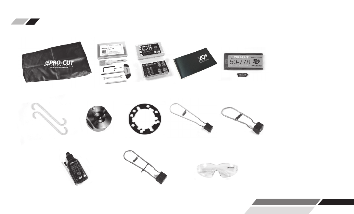
1 50-752 Lathe Cover
1 50-660 Tool Kit
1 50-179 Lug Nut Kit
1 50-763 Owners Manual
2 37-034 Caliper S-Hooks
1 50-046 Nose Cone Extension
1 30-791 Spacer Ring
1 50-703 Chip Deflector
1 50-778 Cutting Tips
1 50-744 Large Chip Deflector
1 50-376 Way Oil
1 50-754 Chip Deflector
1 37-1900 Safety Glasses
*IMAGES NOT TO SCALE
STANDARD ACCESSORIES INCLUDED WITH THE X9D BENCH LATHE
50-752 50-660 50-179
37-034 50-046 30-791 50-703
50-763 50-778
50-744
50-376 37-190050-754

PG / 14 800.543.6618
Carefully inspect all items received in this shipment. If there is damage or evidence of mishandling in transit, determine
the extent of damage and notify the transit company as well as Pro-Cut or your local Pro-Cut rep immediately. Although we
are not responsible for damage incurred in transit, we will assist in the preparation and filing of claims.
SAFETY INFORMATION
This manual has been prepared for the operator and those responsible for the maintenance of the brake lathe. Its purpose,
aside from proper maintenance and operations, is to promote safety through the use of accepted practice. READ AND
UNDERSTAND THE SAFETY AND OPERATING INSTRUCTIONS COMPLETELY BEFORE OPERATING THE MACHINE.
In order to obtain maximum life expectancy and efficiency from your brake lathe; follow the operating instructions and
maintenance manual carefully. The specifications put forth in this manual were in effect at the time of publication. How-
ever, owing to Pro-Cut’s policy of continuous improvement, changes to the specifications may be made at any time without
obligation on the part of Pro-Cut International, LLC.
ACCEPTANCE FROM TRANSPORTATION CARRIER

WWW.PROCUTUSA.COM PG / 15
Read, understand and follow the safety and operating instructions found in this manual. Know the limitation and hazards
associated with operating the machine.
SAFETY INSTRUCTIONS
1.
SPECIAL PRECAUTIONS: The Pro-Cut X9D brake lathe was designed to machine the portions of the brake disc that come
in contact with the friction material. When used according to the instructions herein, this lathe will perform satisfactorily
within the work piece size range designed for this model. During the machining operation, the work piece rotates. Be espe-
cially cautious of rotating spokes and mounted accessories. During machining, material removal may cause a sharp edge
to be generated, where a chamfer or radius previously existed. Use care in handling machined parts.
GROUNDING THE MACHINE: In the event of a malfunction or breakdown, grounding provides a path of least resistance for
electric current to reduce the risk of electric shock. The lathe is equipped with an electric cord having an equipment-
grounding conductor and a grounding plug. The plug must be plugged into a match outlet that is properly installed and
grounded in accordance with all local codes and ordinances. Do not modify the plug provided. If the plug will not fit the
outlet, have the proper outlet installed by a qualified electrician. If repair or replacement of the electric cord or plug is nec-
essary, do not connect the to a live outlet until repairs are performed. Check with a qualified electrician or service personal
if the grounding instructions are not completely understood, or if in doubt as to whether the lathe is properly grounded.
EXPLOSION RISK: This machine generates internal sparks. Do not use at less than 18” [0.46m] above grade level, and never
use below grade level. Work area should be well ventilated and free of explosive funes.
2.
3.
4.

PG / 16 800.543.6618
USE PROPER EXTENSION CORD: Use only 3-wire extension cords that have 3-prong grounding plugs and 3-pole recep-
tacles that accept the lathe’s plug. Repair or replace damaged or worn cord immediately. Make sure your extension
cord is in good condition. When using an extension cord, be sure to use one that is 15’ or less and 14ga or heavier (i.e.
12ga). An undersized cord can cause a drop in line voltage resulting in a loss of power and overheating.
EYE SAFETY: Wear an approved safety face shield, goggles, or safety glasses. (Ordinary eyeglasses are not safety glasses
and do not provide the degree of protection necessary.)
RESPIRATORY SAFETY: If the operation or area is dusty a face or dust mask should be used.
PERSONAL PROTECTION: Before operating the machine, remove tie, rings,watches and other jewelry, and roll up sleeves
above the elbow. Remove all outer loose clothing and confine long hair. Protective type footwear must be worn. Hearing
protectors must be used where noise exceeds the level of exposure allowed in Section 1910.95 of the OSHA Regula-
tions. DO NOT WEAR GLOVES.
DO NOT USE LATHE IN DANGEROUS ENVIRONMENT: Don’t use the lathe in damp or wet locations, or expose the lathe to
rain. Keep the work area well lighted.
DO NOT OVERREACH: Maintain a balanced stance and keep your body under control at all times.
SAFETY INSTRUCTIONS (continued)
5.
6.
7.
8.
9.
10.

WWW.PROCUTUSA.COM PG / 17
HAND SAFETY: Keep hands away from moving parts when the machine is under power. Never clear chips or debris when
the machine is under power and never use your hands to clear the chips. Never use compressed air to clean machine;
use only a soft bristle brush or vacuum cleaner.
MACHINING PREPARATION: Tighten all appropriate locks before operating the lathe. Be sure work piece is secured.
Remove adjusting keys and wrenches. Be sure to check to see that all adjusting wrenches are removed from the lathe
before turning the machine on.
CHECK DAMAGED PARTS: Before further use of the lathe, a guard or other part that is damaged should be carefully
checked to determine if it will operate properly and perform its intended function. Check for alignment of moving parts,
binding of moving parts, breakage of parts, mounting, & any other conditions that may affect the lathe’s operation. A
guard or other part that is damaged should be properly repaired or replaced.
MAINTAIN TOOLS WITH CARE: Keep tools sharp and clean for best and safest performance. Follow instructions for lubri-
cating and changing accessories.
NEVER STAND ON LATHE: Serious injury could occur if the lathe is tipped or if the cutting tool is unintentionally con-
tacted.
SAFETY INSTRUCTIONS (continued)
11.
12.
13.
14.
15.

PG / 18 800.543.6618
MACHINE CAPACITY: Do not attempt to use the machine for other than car or truck discs, or for operations for which the
machine was not intended.
CARELESS ACTS: Give the work you are doing your undivided attention!
Disconnect Electrical Power before performing any service, maintenance, or changing of accessories or adapters.
JOB COMPLETION: If the operator leaves the machine area for any reason,the machine should be turned off, and the
spindle brought to a complete stop before the operator departs. In addition if the operation is complete, the operator
should clean the machine and work area. NEVER CLEAN THE MACHINE WITH THE POWER ON.
REPLACEMENT PARTS: Use only Pro-Cut replacement parts and accessories, risk of injury may result in accessories other
than those recommended are used.
MISUSE: Do not use the machine for other than its intended use. If used for other purposes, Pro-Cut International, LLC,
disclaims any expressed or implied warranty, and holds itself harmless for any injury or loss that may result.
SAFETY INSTRUCTIONS
16.
17.
18.
19.
20.
21.

WWW.PROCUTUSA.COM PG / 19
The X9D Multi-Speed Lathe has a feed rate of .005” [.127mm] per revolution and a variable spindle speed.
Choose spindle speed based on the size of the work piece, slower for larger diameter parts.
75-80% power may also give a better surface finish. For some trucks with speed-sensitive locking axles, you may
need to reduce the speed to 50% to stay below lock-up rpm.
No guarantee can be made for inserts not purchased from Pro-Cut, as insert corner radius, relief angle, material
composition and edge preparation can have a strong effect on cutting quality, insert lift, and tendency of the work
piece to vibrate. Always use Genuine Pro-Cut 50-778 inserts for best results.
The maximum recommended depth of cut is 0.012” / 0.3mm per insert.
X9D MULTI-SPEED BRAKE LATHE OPERATION PROCEDURES OPERATION

PG / 20 800.543.6618
VEHICLE PREPARATION
Before lifting the vehicle, the front wheels should be straight and the parking brake should be off, with the
transmission in neutral, and the traction control turned off.
NOTE: Remember to index mark rotors before removing them so you
can be sure they are returned to the same positions on the hub.
1. Raise the vehicle according to the lift manufacturer’s instructions. Raise until the wheel hub is about belt level.
2. Check wheel bearings for damage or excessive play. If this or any other wheel service is required, it should be performed
before match-machining the rotors as loose or damaged bearings will keep the lathe from doing the most accurate job possible.
3. Remove the wheels. Remove the brake calipers and suspend them out of the way of moving parts such as half shafts and
CV joints using the yellow S-hooks provided (pn 37-034). Be sure to remove all wheels that may turn when the lathe is
turned on.
4. Use Pro-Cut part number 37-996 or 37-997 wheel hub cleaning kit, or other suitable wheel hub cleaning tool to remove rust
or debris. Clean all material from the mounting area.
5. The rotor on the side of the vehicle that is not to be machined should be marked and removed if it is free on the hub or
secured with at least 2 lug nuts. Match marking the rotors to the hub is very important.
6. Use a micrometer to measure rotor thickness and determine how much material may be removed from the rotor by com-
paring to brake spec. Visually inspect for deep rust or grooves. This inspection will help determine the depth of the cut.
Table of contents
Other Pro-Cut Lathe manuals


Popular Lathe manuals by other brands

Axminster Craft
Axminster Craft AC355WL Original instructions

YANGZHOU SUPER MACHINE TOOL
YANGZHOU SUPER MACHINE TOOL CD6240 Instruction manual and parts list

Jet
Jet EVS-1440B Operating instructions and parts manual

Laguna Tools
Laguna Tools Platinum 18/47 Series manual

WilTec
WilTec 61591 Operation manual

HPC
HPC AUTOMATE 6666HQT manual


