STS Instruments Siloxane User manual

STS Instruments Ltd,
Service & Maintenance
Manual
201
8
SILOXANE MONITOR MAN AL
STS INSTR MENTS COPYRIGHT 2018
STS INSTR MENTS LTD
|
www.siloxanemonitoring.com

1
16/08/2017, STS Instruments Ltd, Service & Maintenance Manual
TABLE OF CONTENTS
2.0 Manual Guide ..................................................................................................... 2
2.1 Document Version ............................................................................................ 2
2.2 Symbols sed .................................................................................................. 2
3.0 Safety Information ............................................................................................... 3
3.1 Environmental parameters .................................................................................. 3
3.2 Instrumentation Safety Symbols ............................................................................ 4
4.0 Service Schedule ................................................................................................. 5
5.0 Maintenance -Weekly .......................................................................................... 10
5.1 Fittings & cables ............................................................................................. 10
5.2 Automated Water Trap ..................................................................................... 10
5.3 Coalescing Filter ............................................................................................. 10
5.4 Instrument Air intake fan ................................................................................... 10
5.5 Instrument Exhaust Fan ..................................................................................... 10
5.6 Kiosk Exhaust Fan ............................................................................................ 10
6.0 Maintenance –Annually ........................................................................................ 10
6.1 Coalescing Filter ............................................................................................. 10
6.2 Flame Arrestor ............................................................................................... 10
6.3 Biogas regulator pressure set .............................................................................. 10
6.4 Heated line .................................................................................................... 11
7.0 Maintenance Menu .............................................................................................. 11
7.1 Access to menu ............................................................................................... 11
8.0 Fault Identification ............................................................................................. 14
8.1 Instrument Error codes ..................................................................................... 14
8.2
4-20mA Remote Data Error codes ................................................................... 14
9.0 Flow Diagrams ................................................................................................... 15

2
16/08/2017, STS Instruments Ltd, Service & Maintenance Manual
2.0 MAN AL G IDE
2.1 DOC MENT VERSION
Issued by
Author
Issue Date
Revision Number
STS
Jim Ward
18/10
/2016
1.0
STS
Jim Ward
20/10/2016
1.1 Final
STS
Jim Ward
06/02/2017
1.2
Amends P6.
STS
Jim Ward
26/05/2017
1.3 4
-
20mA error codes P14
STS
Jim Ward
16/08/2017
1.4 Added kiosk schematic and gas flow through kiosk P18
2.2 SYMBOLS SED
Safety Warning
Identifies potential
hazards to either
the user or the
installation.
Failure to follow this
information may result in
physical injury that in some
cases could be fatal, cause
irrevocable damage to the
instrument or damage to the
envi
ronment.
Electrical Hazard
Identifies specific
electrical hazards
to the user.
Failure to follow this
information may result in
physical injury that in some
cases could be fatal or may
cause irrevocable damage to
the instrument.
Notes
Identifies
areas
where clarification
may be required.
Should at any point you require additional help or information on the use or installation
of the system please contact STS directly at: sales@safetrainingsystems.com or +44 (0) 1344
483563

3
16/08/2017, STS Instruments Ltd, Service & Maintenance Manual
3.0 SAFETY INFORMATION
3.1 ENVIRONMENTAL PARAMETERS
•The Siloxane Monitor is not weatherproof and must be housed in a suitable kiosk or cabinet
if sited outside of a building
•If siting inside a building consideration should be given to the local conditions as regards to
dust, moisture and ventilation the Monitor is available supplied in a 19” rack case suitable
for indoor use with inbuilt thermostatically controlled extraction fans.
The STS Siloxane Monitor operates from a 110V mains supply, the instrument case
should not therefore be opened without having first isolated the power supply and disconnected
the kettle lead form the rear of the instrument. The high voltage section of the instrument is
protected by clear cover – this should not be removed unless necessary- having followed the above
instructions. FAIL RE TO ISOLATE THE S PPLY MAY RES LT IN ELECTRIC SHOCK.
It is the responsibility of the owner of the instrument to complete a risk assessment on its
installation, operation and servicing before being commissioned for use.
Inhalation of gases may be harmful to health, it is the responsibility of the operator to ensure they
have adequate training in the safety aspects of handling biogas/landfill gas and that they follow
appropriate procedures at all times. The vent/exhaust form the instrument must be piped to an
area designated safe to discharge to atmosphere- a flame arrestor may be required to be fitted.
Installation and Maintenance of the unit should only be carried out by suitably trained personnel
according to the applicable code of practice.
Maintenance should be carried out only using STS approved replacement parts and components –
use of substitutes will invalidate the warranty and may be hazardous to both operator and
instrument.
No alterations should be made to the instrument or its ancillary components.
Failure to comply with the instructions in this manual could result in injury to the user.
The instrument captures fuel gas any work associated with the instrument must be carried out by a
class of person competent and certified to do so.
Should at any point you require additional help or information on the safe installation or
use of the system please contact STS immediately at: sales@safetrainingsystems.com or +44
(0) 1344 483563
4
16/08/2017, STS Instruments Ltd, Service & Maintenance Manual
•The monitor is suitable for use between 5C and 45C without additional cooling/heating
required.
•Gas supply to the instrument should be at a minimum of 200mbar
•Adequate ventilation/air passage around the instrument should be provided.
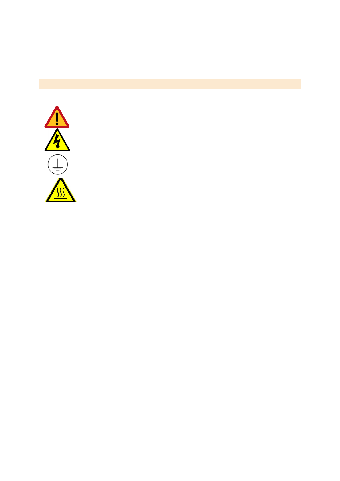
3.2 INSTR MENTATION SAFETY SYMBOLS
Caution
Electrical Hazard
Earth Point
Hot Surface

5
16/08/2017, STS Instruments Ltd, Service & Maintenance Manual
4.0 SERVICE SCHED LE
External
Area Instructions
Nitrogen Cylinder
and Piping
Make sure Nitrogen Cylinder is secured safely. Record cylinder size/type. Check
for leaks at Regulator using Snoop, redo connection if leaks present. Record
cylinder and regulator pressure. Make sure regulator is set to 1Bar. Piping to
instru ent should be fastened with no da age or degradation. If da age is
present, replace the whole Nitrogen line.
Sa ple Line Piping
Check there are no leaks at sa ple supply, redo connection if a leak is present.
Pipe work to the instru ent should be fastened securely,
insulated/weatherproofed with the heated line installed. Check the visible
piping for da age or degradation. If da age is present, atte pt to replace the
da aged section.
Heated Line and
Weatherproofing
Check whether the heated line has been installed correctly. Record the set
te perature and easure the te perature inside the insulation using a
te perate probe. Check the insulation for da age and degradation. If da age
is present, atte pt to repair that section.

6
16/08/2017, STS Instruments Ltd, Service & Maintenance Manual
Vent and Drain
Piping
Check that the Vent and Drain Piping are fastened securely and have no
da age or degradation. If da age is present, replace the whole line. Visibly
check the vent/drain line for any blockages. If a blockage is suspected, confir
this by connection the Nitrogen to the vent/drain line and pressuring the line.
These lines are open to at osphere and should not retain any pressure.
Confir that the vent/drain line is venting into a suitable location. If the vent
has a fla e arrestor installed, re ove the arrestor and purge it with Nitrogen at
1Bar.
Leak Check
Run a leak check on the Nitrogen lines. The leak check shall be perfor ed with
the nitrogen cylinders connected but closed. The service engineer shall verify
no discernible pressure drop over 30 inutes.
Any checks on the biogas syste shall be perfor ed in accordance with the
Installation Manual.
Kiosk
Area Instructions
General Kiosk
Clear any debris, check weatherproofing. Fasten any loose cables
and piping. Record the general state of kiosk and any da aged
parts.
Fla e Arrestor
Disconnect then purge the Fla e arrestor with 1Bar Nitrogen,
venting onto a sheet of white paper. Record any residue found. If
excessive residue is found replace fla e arrestor.
Coalescing Filter Note any Discolouration and Moisture. Replace with New Filter.

7
16/08/2017, STS Instruments Ltd, Service & Maintenance Manual
Water Trap
Record any visible water or oisture inside the water trap.
Record any visible corrosion to the fittings, if so replace Water
Trap.
Fans
Record the previously set ther ostat te perature. Ther ostat
should be set to 25degC. Clear any debris around the fans, filters
and cowls. Check the kiosk fans operate when ther ostat is
triggered by changing the threshold te perature. If they don't,
check the with a ulti- eter to confir the ther ostat is
powering the fan. If it is, replace the Fan, else replace the
ther ostat and repeat to confir the fan is working.
Instru ent Intake and Exhaust Clear any debris. Record any da age to the join/seal to the
instru ent and to the kiosk.
Mains and Electrical Visually inspect and record any da age and degradation. If any
da age, disconnect the supply and speak to the anufacture.
Instrument
Area Instructions
General Instru ent
Record the general condition of Instru ent casing, bulkhead gas
fittings and ains cable. Clear any internal debris.
Particle Filters
Re ove two particle filters and blow through with 1Bar Nitrogen
venting onto a sheet of white paper. Record any residue found. If
excessive residue is found replace particle filter.
Fans
Check whether instru ent intake and exhaust fans start up upon
powering the instru ent. If they do not, using a ulti- eter,
easure the voltage to the fans. If they aren't getting power,
return instru ent to the anufacturer.

8
16/08/2017, STS Instruments Ltd, Service & Maintenance Manual
PCB, LCD and keypad.
Check LCD and keypad are fully operational by navigating the
enus of the instru ent. Record any da age and degradation.
Check LCD and keypad are fully operational.
Pipe work
Check the internal piping is fastened, and there is no da age or
degradation. Replace any da aged sections.
Leak Check
Via View Stats in the Maintenance enu. Pressurise with N2 in
Phase 0, close N2 supply, allow 10 ins for stabilisation. Then
start recoding the te perature and if after 5 ins there has been
a 20% drop, check all the connections and repeat. If there is still
a leak, this line will need detailed inspection with the potential
for so e or all of the piping to need replacing. Then pressurise
with N2 in Phase 6 with the vent closed, close N2 supply, likewise
repeat the above step recording the pressure drop.
Pu p and Relief Valve
Via View Stats in the Maintenance enu, set to phase 2 and
record the pu p pressure. If the pressure is less than
approxi ate 15PSI, adjust relief valve and repeat. If the pressure
does not change, check for leaks.
Nitrogen Regulator
Via View Stats in the Maintenance enu, set to phase 0. Record
the nitrogen pressure. If the pressure is not approxi ately 10PSI,
adjust the regulator. If the pressure doesn't change, check the
cylinder is at 1Bar and check the internal piping for gas leaks. If
the issue still is there, replace the regulator.
Heaters
Via View Stats in the Maintenance enu, set to phase 1. Record
the Concentrator te perature. It should stabilise around
240degC. If it doesn't, return instru ent to anufacturer. To
check the Per eation heater, run a calibration cycle with a
te perature probe in the per eation oven. This probe should
stabilise around 80degC. If it doesn't return instru ent to
anufacture.

9
16/08/2017, STS Instruments Ltd, Service & Maintenance Manual
Flow Measure ent
Via View Stats in the Maintenance enu, in phase 6, record the
internal flow easure ent and co pare it with an external flow
easure ent on the vent line. If these differ by ore than 20%
return instru ent to anufacture.
Te perature, Pressure and CH4
sensors
Via View Stats in the Maintenance enu, in phase 1, record the
te peratures, pressures and CH4 values.
Solenoids
Via View Stats in the Maintenance enu. In Phase 0, if Solenoid
2 is operational the pu p pressure should be approxi ately
zero. In phase 3, if solenoid 4 is operational the pu p pressure
should be greater than 1PSI but less than 14PSI. To test Solenoid
1 and 3, run calibration cycle with a D5 sa ple and if the correct
ass is present the solenoid is operational.
Calibration
Via Maintenance Menu, run a calibration cycle. Leave the first
cycle blank, then use 20ul of 1 g/ l D5. Attach Calibration
Report. Adjust the Calibration coefficient to achieve a reading of
20ug. Replace per eation oven seal once finished.
Other manuals for Siloxane
4
Table of contents


