Stuart Turner Mainsboost Charger MBC 12 Guide

- 1 –
Read this manual carefully before commencing installation.
This manual covers all wall mounted Mainsboost Charger units.
Mainsboost Charger Pump MBC 12 & Bypass Kit – Wall Mounted
Mainsboost Charger Installation,
Operation & Maintenance Instructions
Please leave this instruction booklet with the home owner as it contains
important warranty, maintenance and safety information
MAINSBOOST
CE compliant product
5
WARRANTY

- 2 –
PRODUCT DESCRIPTION
Mainsboost Charger MBC 12 pump assembly, consists of case, pump and connecting
hoses.
APPLICATION
Mainsboost Charger MBC 12 is designed to offer stored clean, potable cold water
under pressure for all domestic or small commercial applications where mains water is
insufficient to offer consistent and reliable water services.
Installation parameters must not exceed the values given in the technical
specifications.
STORAGE
If this product is not to be installed immediately on receipt, ensure that it is stored in a
dry, frost and vibration free location in its original packaging.
CONTENTS Page
Checklist ...........................................................5
Introduction .........................................................6
Important Facts – read before commencing installation ......................7
Location ............................................................8
Terminology .........................................................9
Installation ..........................................................10
Electrical ...........................................................12
Commissioning ......................................................14
Technical Specification ................................................17
Trouble Shooting .....................................................18
Warranty ...........................................................19

- 3 –
WARNINGS:
zMainsboost Charger MBC12 must not be used for any
other application without the written consent of
Stuart Turner Limited and in particular, must not be
connected directly to the mains water supply.
zThis appliance can be used by children aged from
8 years and above and persons with reduced
physical, sensory or mental capabilities or lack of
experience and knowledge if they have been given
supervision or instruction concerning use of the
appliance in a safe way and understand the hazards
involved.
zChildren shall not play with the appliance.
zCleaning and user maintenance shall not be made by
children without supervision.
zMaximum head (closed valve) 43 metres.
zThe motor casing can become very hot under normal
operating conditions. Care must be taken to ensure it
cannot be touched during operation.
zThe electrical installation must be carried out
in accordance with the current national electrical
regulations.
zThe electrical installation must be installed by a
qualified person.
zIn the interests of electrical safety a 30 mA residual
current device (R.C.D. not supplied) should be
installed in the supply circuit. This may be part of a
consumer unit or a separate unit.
zBefore starting work on the electrical supply ensure
power supply is isolated.
zDO NOT allow the supply cord to contact hot
surfaces, including the motor shell, pump body or
pipework. The cord should be safely routed and
secured by cable clips.

- 4 –
zThis appliance must be earthed via the supply cord,
which must be correctly connected to the earth
point located in the terminal box.
zThe supply cord and internal wiring within the
terminal box are routed and secured to ensure
compliance with the electrical standard
EN 60335–1. It is essential that prior to any
disturbance of this internal wiring, all cable routing
and securing details are carefully noted to ensure
re-assembly to the same factory pattern is always
maintained.
zIf the supply cord is to be changed or is damaged, it
must be replaced with a special cord assembly
available from Stuart Turner or one of their approved
repairers.
Please read installation details carefully as they are intended to ensure this product
provides long, trouble free service. Failure to install the unit in accordance with the
installation instructions will lead to invalidation of the warranty. These instructions
must be left with the product.

- 5 –
CHECKLIST
Item Description Qty Item Description Qty
Package
1
1 Mounting tray 1
Package
1 cont..
4Hose washers 2
2 Pump assembly 1 4 Fixing screws 4
3 Hoses 2 4 Wall plugs 4
4Ball valve 2Package
2
1Ball valve 1
2Single check valve 1
Your product may vary slightly from the picture above.
IMPORTANT: Your Mainsboost Charger MBC 12 system will be delivered in two
boxes. Please check the contents within 24 hours of receipt and if any component is
damaged, please contact Stuart Turner Ltd immediately.
Package 1
Fig. 1
2
1
3
4
Package 2
Fig. 2
Image not to scale
Image not to scale
12

- 6 –
1 INTRODUCTION
1.1 Congratulations on buying a Mainsboost Charger MBC 12 system, designed to
offer consistent and reliable water services throughout the property.
1.2 Trademarks & Trade Names:
‘Mainsboost’ ‘Mainsboost Plus’ and ‘Mainsboost Charger’ are registered
Trademarks of Stuart Turner Ltd.
1.3 How the Mainsboost Charger MBC 12 System works:
The Mainsboost vessel stores water from the rising main in a sealed
water chamber, separated from the air space by a rubber diaphragm and
pressurised to an optimum setting. When water is drawn off by downstream
services, the water from the mains is supplemented by the water from the
Mainsboost unit to provide a balanced supply at consistent pressure to
downstream services.
On occasions where the static pressure is less than 2 bar, a charger pump unit
can be used to ensure sufficient pressure is available for the Mainsboost
system to continue to function correctly.
The Mainsboost Charger MBC 12 pipework manifold incorporates a unique
‘green energy’ bypass. If the incoming mains water supply delivers
more than 12 l/min this bypass should be left open to allow any
additional flow rate to pass directly into the Mainsboost vessel via the integral
non-return valve. If the incoming flow rate is less that 12 l/min the bypass
valve should be left closed in order to ensure optimum efficiency of the
Charger pump.

- 7 –
2 IMPORTANT FACTS READ BEFORE COMMENCING INSTALLATION
A Commissioning
2.11 Ensure the pump is primed as described in the priming section before
starting, damage to the shaft seal will result otherwise. See Section 8.16 –
Commissioning.
B Water temperature
This unit is designed for cold water applications only which should not exceed the
following values:
2.12 The maximum allowable water temperature is 35 oC.
2.13 The minimum allowable water temperature is 4 oC.
C Pipework – General
2.14 Secure pipework: Ensure pipework to and from the Mainsboost Charger
MBC 12 is independently supported & clipped to prevent forces being
transferred to inlet and outlet branches of pump. Flexible hoses supplied
must be used.
2.15 Flux: Solder joints must be completed and flux residues removed prior to
pump installation (flux damage will void any warranty).
2.16 Pipework design: Care should be taken in the design of pipework runs to
minimize the risk of air locks e.g. use drawn bends rather than 90obends.
D Plumbing Installation Regulations
2.17 The plumbing installation must comply with the current water and building
regulations.
2.18 The plumbing installation must be installed by a qualified person.
- 8 –
3 LOCATION GENERAL
3.11 Access: For emergencies and maintenance the Mainsboost
Charger MBC 12 must be easily accessible.
3.12Protection: The system must be located in a dry position, and
protected from freezing. Avoid environments which have a high
ambient temperature, high humidity or excessive condensation
and salt damage, etc.
3.13 Ventilation: Ensure an adequate air flow to cool the pump.
Separate the pump from other appliances that generate heat.
3.14 Safety: The motor casing can become very hot under normal
operating conditions. Care must be taken to ensure it cannot be
touched during operation.
3.15Water retention: Site the pump in a location where in the unlikely
event of a water leak, any spillage is contained or routed to avoid
electrics or areas sensitive to water damage.
3.16 Static inlet pressure: Ensure the static inlet head at the pump does not
exceed the values shown in the table under point 7.13.
3.17 Incoming mains water pressure: The incoming water pressure of at least
0.1 bar is required.
3.18 Ensure that location of the unit allows adequate space to give reasonable
access to all parts to accommodate service/commissioning.
3.19 Ambient temperature: The pump must be sited in a location where the
maximum ambient temperature does not exceed 40 oC.
3.20 Pipework: Pipework should be sized to ensure optimum performance of the
system.
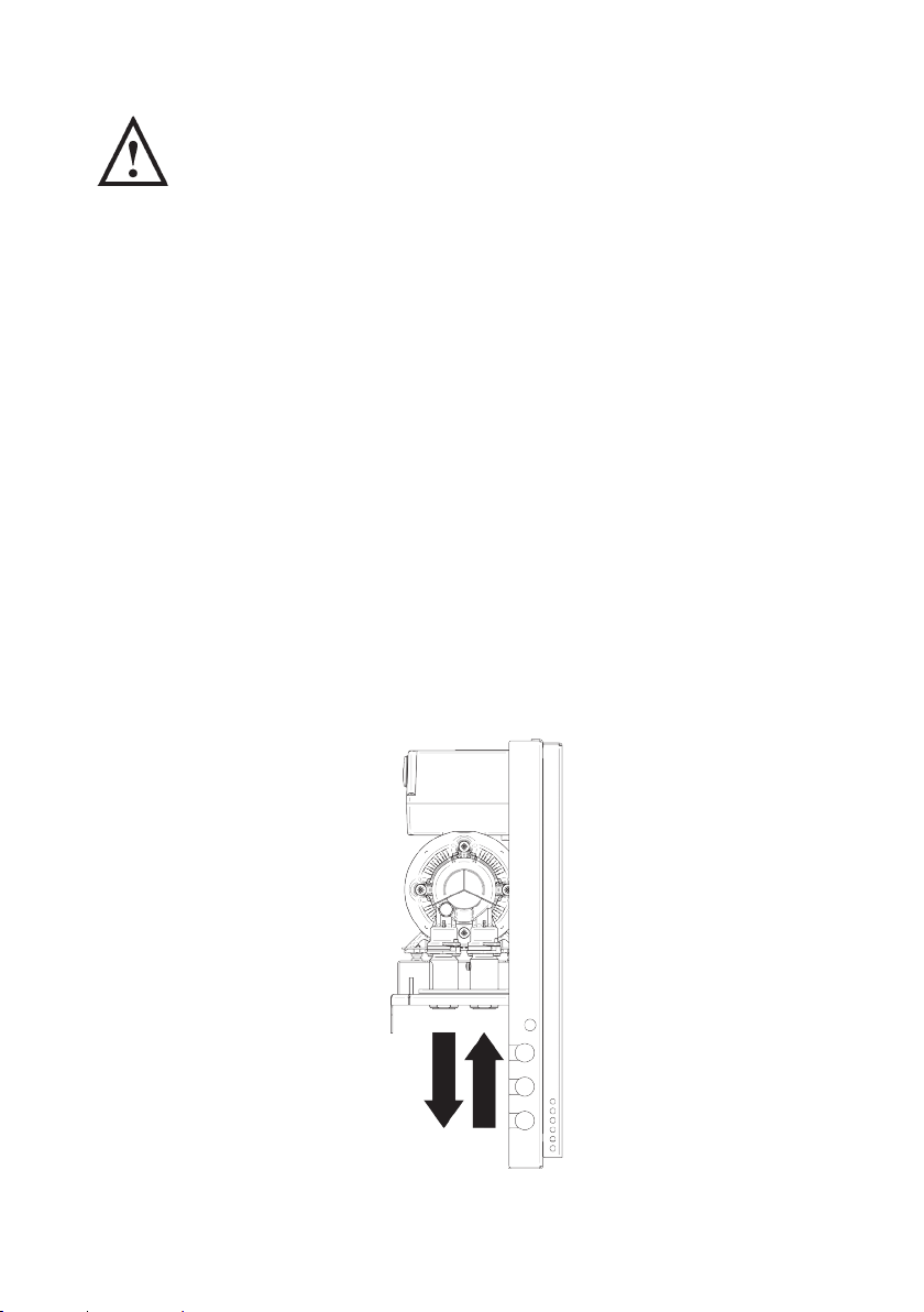
3.21 Direction of flow: See Fig. 2 to identify the suction and discharge
connections.
Fig. 2
Inlet
Outlet
- 9 –
4 TERMINOLOGY
4.11 Upstream Line-in Kits (ULK)
Monobloc upstream line-in kit:
The Mainsboost Monobloc is a patent pending mains regulating device
and should be installed on the rising main between the stopcock and the
Mainsboost vessel. The Monobloc unit is used on 22mm or 28mm upstream
line in kits.
Upstream line-in kits:
Upstream line-in kits for 35mm, 42mm & 54mm installations use separate
regulating components and should be installed on the rising main between
the stopcock and the Mainsboost vessel.
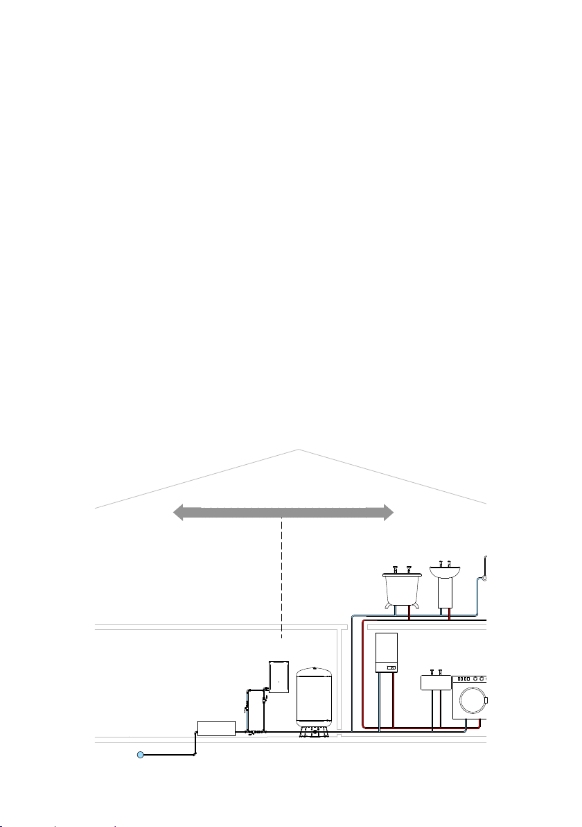
4.12 System Designation
It is important to understand what upstream and downstream refers to before
starting the installation.
Upstream
The term ‘Upstream’ refers to the system configuration from the consumer’s
stopcock to the point where the supply reaches the inlet port of the
Mainsboost vessel.
Downstream
The term ‘Downstream’ refers to the system configuration from the outlet
tapping on the Mainsboost vessel, along the distribution header (if configured
in this way) and into the distribution pipework and outlets. This includes hot
and cold services where both are present (see Fig. 3).
UPSTREAM DOWNSTREAM
UPSTREAM
LINE-IN KIT
Fig. 3 System designation

- 10 –
5 INSTALLATION
Select best position to mount Charger pump unit (Fig. 4).
1) Fit mounting plate onto wall ensuring level (Fig. 5).
2) Hook pump assembly onto mounting plate and secure in place using M6 set
screw (Fig. 5).
Fig. 5
Fig. 4
Mounting plate
Pump assembly
M6 set screw
Selected position
Mains supply ULK kit
(supplied
with vessel)

- 11 –
3) Your charger will have been supplied with either a green energy lever valve
and check valve to suit the main water supply size of (22, 28 or 35 mm).
Having ensured the stopcock is turned off and (if installing on an existing
Mainsboost system) drained it, remove a section of pipe to allow fitting
of 2 tee pieces (not supplied), the lever valve and check valve (Fig. 6).
4) The Charger unit has been designed to allow pipework connections to be
made in the most convenient way, select the best route.
5) Care should be taken not to kink the hoses or bend them through an angle
greater than 30 degrees.
6) Route 15 mm feed and return from the tees inserted in the main, passing
through the isolating valves supplied (Fig. 6).
7) Ensure grommets are fitted correctly in all case apertures to ensure the
pipework does not vibrate against the case (Fig. 6).
8) Install the supplied ULK kit as per the instructions supplied with it and in the
location shown in figure 6.
Fig. 6
Supplied with MBC 12
Isolating
valve
Stopcock
Check valve
Mains supply
Bypass kit
Isolating
valves
Direction
of flow
ULK kit
(supplied
with vessel)

- 12 –
6 ELECTRICAL
6.11 Regulations: The electrical installation must be carried out in
accordance with the current local regulations by a qualified person.
6.12 Safety: In the interests of electrical safety a 30 mA residual current
device (R.C.D. not supplied) should be installed in the supply
circuit. This may be part of a consumer unit or a separate unit.
6.13 Before starting work on the electrical supply ensure power supply
is isolated.
6.14 DO NOT allow the supply cord to contact hot surfaces, including
the motor shell, pump body or pipework. The cord should be
safely routed and secured by cable clips.
6.15 Earthing: This appliance must be earthed via the supply cord, which must be
correctly connected to the earth point located in the terminal box.
6.16 Connections: The pump must be permanently connected to the fixed wiring
of the mains supply using the factory fitted supply cord, via a dedicated
double pole switched fused spur off the ring main.
6.17 Wiring of connection unit:
WARNING: This appliance must be earthed.
The wires in the mains lead (supply cord) are coloured in accordance with the
following code:
Green and Yellow: Earth
Blue: Neutral
Brown: Live
As the colours of the wires in the mains lead of this appliance may not
correspond with the coloured markings identifying the terminals in your
connection unit proceed as follows:
zThe wire which is coloured green and yellow must be connected to the
terminal in the connection unit which is marked with the letter E or by the
earth symbol: or coloured green or green and yellow.
zThe wire which is coloured blue must be connected to the terminal which
is marked with the letter N or coloured black.
zThe wire which is coloured brown must be connected to the terminal
which is marked with the letter L or coloured red.
- 13 –
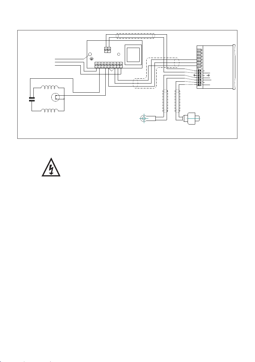
6.18 Wiring diagram:
6.19 Fuse: All models should be protected by a 3 Amp fuse.
6.20 Supply cord replacement:
The internal wiring within the terminal box is routed and
secured to ensure compliance with the electrical standard
EN 60335–1. It is essential that prior to any disturbance of
this internal wiring, all cable routing and securing details
are carefully noted to ensure re-assembly to the same
factory pattern is always maintained.
6.21 If the supply cord is to be changed or damaged, it must be replaced by a
special cord available from Stuart Turner or one of its approved repairers.
MAIN WINDING
THERMOTRIP
CAPACITOR
START WINDING
BLUE
BLACK
L
E
N
230 VAC/1PH/50Hz
SUPPLY
GREEN/YELLOW
BROWN
BLUE
1
2
3
4
5
6
CONTROLLER
BLUE (LINK WIRE)
BROWN
BROWN
TEMPERATURE
SENSOR PRESSURE
SENSOR
BLUE
BROWN
BROWN
BLUE
BLACK
BLUE
BLACK
BROWN
BROWN
BLUE
BROWN
BLUE
BLUE
BROWN
BLUE
BROWN
N N1 N2 L5 L4 L3 L2 L1 L
12 VAC
7
8
9
10
12 -VE
13 +VE
BLUE
BLUE (LINK WIRE)
NOT USED NOT USED
11
Fig. 7

- 14 –
7 COMMISSIONING
7.11 System check: Ensure that the electrical supply to the pump is switched off
before opening the mains water supply stopcock and checking for leaks.
7.12 Check mains static pressure:
zNow close outlets and check pressure gauge after ‘Y’ strainer – for static
mains pressure and note it.
zTurn stopcock off and leave outlet taps open.
7.13 Check the chart below for the correct pump pressure setting against the
static mains pressure recorded.
Warning: NOTE PRV setting must not exceed 5.0 bar.
Refer to the Mainsboost instruction manual for the correct commissioning of
the vessels.
MBC 12 pump max.
set pressure
Static mains
pressure
Set vessel
pre-charge
pressure to
Differential Set PRV maximum
setting to
bar bar bar bar
3 bar 1.0 1.2 1.8 1.0
3 bar 1.5 1.2 1.8 1.5
3 bar 2.0 1.2 1.8 2.0
3.5 bar 2.5 1.7 1.8 2.5
3.5 bar 3.0 1.7 1.8 2.5
- 15 –
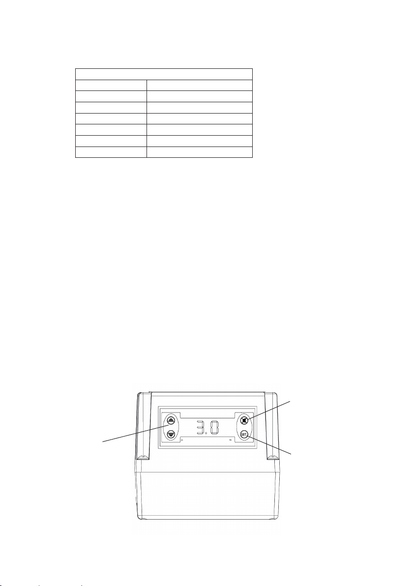
7.14 Control module:
The control module (Fig. 8) has been factory pre-set to the following
conditions.
Should the parameter need changing follow these steps.
zThe pump parameters are displayed in the following sequence:
Set point (SP),
Differential (DIFF),
Low pressure trip (LPR),
High pressure trip (HPR),
Pump run timer (PRT),
Pump Number (NPM),
Relay setting (CRE),
Number of alarms (NAL1/NAL2),
Hours run (HR1/HE2).
zPress and hold the set button for 5–7 seconds. (This gains access to the
pump parameters).
zPress the up/down arrows to change the selected parameter(s) to the
desired value.
zAfter changing the required parameter(s) press the set button twice in
quick succession to lock the new value into the controller memory.
zIt is possible to scroll through all the pump parameter values by simply
pressing the set button once after each parameter value has been
displayed.
Settings as per factory preset:
Set point SP: 3 bar
Diff pressure DIFF: 0.5 bar
Low pressure LPR: 0.2 bar
High pressure HPR: 4.5 bar
Pump run timer PRT: 180
Pump number NPM: 2 (do not tamper)
CRE setting 0
Fig. 8
Up/down arrows
allow changes to
pump parameter
values
Alarm mute button
Set button enables
access to pump
parameter values

- 16 –
7.15 On completion of the installation, follow the commissioning process below.
zLeave pump power switched off.
zLeave all outlet valves closed.
zTurn on stopcock and open inlet ballvalve, both pressure gauges on
inlet and PRV will start to show movement as the mains pressure fills the
system.
zCheck for leaks on all joints made.
zDependant on the incoming mains pressure the Mainsboost vessel will
start to fill with water.
zSwitch on the power to the pump, it will sense the pressure in the system
and if less than 3 bar will start to assist filling of the system.
zClose Mainsboost vessel isolation valve
zAllow the pump to continue running until air has been completely purged
from the system, all outlets will have to be opened and closed.
zAll outlets have been closed, open the Mainsboost vessel isolation valve.
zThe pump will continue to run to charge the system, this may take some
time dependant on size and number of Mainsboost vessels fitted.
Once the system is completely full the pump will stop and only start again
if the Mainsboost vessel pressure drops below set point minus the differential
of the pump control.
Green Energy
– Bypass
If the flowrate is greater than 12 l/min leave the isolation valve open.
If the flowrate is less than 12 l/min close the isolation valve.

- 17 –
8 TECHNICAL SPECIFICATION
Pump
Mainsboost Charger
MBC 12–22
44725
Mainsboost Charger
MBC 12–28
44726
General Warranty 5 years (fittings and ULK 2 years)
WRAS approval 1501305
Approvals WRAS, CE
Typical noise 60 dB(A)
Features Pump type Peripheral
Bypass kit 22 mm 28 mm
Mounting Wall
Flexible hoses 2
Dry run protection ü ü
Materials Pump body Brass
Impeller Brass
Mechanical seal EPDM / PTFE / Al. Oxide
Performance Maximum head – closed valve 4.3 bar (43 metres)
Maximum working pressure* 600 kPa (6 bar)
Maximum ambient air temperature 40 oC
Min / Max water temperature Min 4 oC / Max 35 oC
Connections Pump connections G ¾ male
Flexible hoses Connections 15 mm push-in x G ¾ female x 235 mm long
15 mm push-in x G ¾ female x 200 mm long
Motor Type Induction (thermal trip/auto reset)
Duty rating Continuous (S1)
Electrical Power supply (Vac/Ph/Hz) 230 V a.c. / 1 / 50 Hz
Power consumption – P1 398 Watts
Current – full load 1.8 Amps
Fuse rating 3 Amps
Power cable length 1.5 metres (pre-wired)
Physical Enclosure protection IPX4
Width 290 mm
Depth 180 mm
Height – excluding hoses 465 mm
Weight – including fittings 15.3 Kg
Stuart Turner reserve the right to amend the specification in line with its policy of
continuous development of its products.
*NOTE: The maximum pressure that can be applied to the pump under any
installation conditions.
8.11 Noise: The equivalent continuous A-weighted sound pressure level at a
distance of 1 metre from the pump does not exceed 70 dB(A).

- 18 –
9 TROUBLE SHOOTING GUIDE
9.11 Alarm
The ChargerTM controller has an internal alarm buzzer.
When the alarm is triggered the buzzer will sound and a related failure
message will appear on the display.
The alarm will sound when the following conditions occur:- when alarm
sounds investigate and rectify cause.
Then press alarm mute button, alarm will stop.
Remote alarm option
A remote alarm option is available, the ChargerTM unit would need to be
ordered in advance pre-wired for this option. Please consult Stuart Turner.
Attempting to change the ChargerTM MBC 12 wiring will invalidate the
guarantee.
9.12 Alarm fault codes
All alarms automatically reset except Prt and PF1.
Displayed message Fault description Action
AHnt
high temp cut out
Pump head overheating – head
temperature has exceeded the
set Hnt value
Allow pump to cool. Ensure the
ULK check valves and pump
bypass are clear of debris.
BHpr
Hi pressure cut out
The current pressure rises above
the Hpr value
Investigate the cause, then turn
power off and on to reset or
allow self reset.
CLpr
Low pressure cut out
The current pressure falls below
the set Lpr value
Investigate the cause, then turn
power off and on to reset or
allow self reset.
DPrt
pump run time
The pump has run longer than
the set Prt value
Investigate cause, then turn
power off and on. Contact Stuart
Turner if problem persists
EPF1 Pump failure Contact Stuart Turner.

- 19 –
10 YOUR WARRANTY
Congratulations on purchasing a Stuart Turner Mainsboost Charger MBC 12 Pump.
We are confident this product will give you many years of trouble free service as all
our products are manufactured to the very highest standard.
The Mainsboost Charger MBC 12 pump is covered by a five year warranty. The
Mainsboost Monobloc and other ULK/bypass components are warrantied for two
years.
Within the warranty period we will repair, free of charge, any defects in the
Mainsboost Charger MBC 12 resulting from faults in material or workmanship,
repairing or exchanging the part affected or whole unit as we may reasonably
decide.
Not covered by this warranty: Damage arising from incorrect installation, improper
use, unauthorised repair, normal wear and tear and defects which have a negligible
effect on the value or operation of the unit.
Reasonable evidence must be supplied that the product has been purchased within
the guarantee term prior to the date of claim (such as proof of purchase or the
product serial number).
This warranty is in addition to your statutory rights as a consumer. If you are in any
doubt as to these rights, please contact your local Trading Standards Department.
In the event of a claim please telephone ‘TechAssist’ customer support.
+44 (0) 800 31 969 80
You should obtain appropriate insurance cover for any loss or damage which is not
covered by Stuart Turner Ltd in this provision.
Please record here for your reference:
MODEL NO. SERIAL NO. DATE PURCHASED
Stuart Turner Ltd, Henley-on-Thames, Oxfordshire RG9 2AD ENGLAND
Tel: +44 (0) 1491 572655, Fax: +44 (0) 1491 573704
info@stuart-turner.co.uk www.stuart-turner.co.uk
DECLARATION OF CONFORMITY
Machinery Directive – 2006/42/EC
BS EN 12100, BS EN 809
Low Voltage Directive – 2014/35/EU
BS EN 60335–1, BS EN 60335–2–41
EMC Directive – 2014/30/EU
BS EN 55014–1, BS EN 55014–2, BS EN 61000–3–2, BS EN 61000–3–3,
BS EN 61000–4–2, BS EN 61000–4–3, BS EN 61000–4–4, BS EN 61000–4–5, BS EN 61000–4–6,
BS EN 61000–4–11
EMF Directive – 1999/519/EC
BS EN 62233
RoHs Directive – 2011/65/EU
WEEE Directive – 2012/19/EU
IT IS HEREBY CERTIFIED THAT THE STUART ELECTRIC MOTOR DRIVEN PUMP AS SERIAL
NUMBER BELOW, COMPLIES WITH THE ESSENTIAL REQUIREMENTS OF THE ABOVE E.E.C.
DIRECTIVES.
RESPONSIBLE PERSON
AND MANUFACTURER STUART TURNER LIMITED
HENLEY-ON-THAMES, OXFORDSHIRE
RG9 2AD ENGLAND.
Signed .............................................Engineering Manager
Stuart Turner are an approved company to BS EN ISO 9001:2015
Issue No. 3620/05–01 Pt. No. 20537
Table of contents


