Bassi MVD User manual
BATTERY CHARGER
BATTERY CHARGER
MVD
USER'S MANUAL
USER'S MANUAL

1. SAFETY PRECAUTIONS
1
2
3
4
5
6
7
8
9
10
11
12
Before to start using the MVD Charger, read these instructions carefully.
Installation and Service operations can be done by qualified personnel only.
To prevent the risk of electric shock, don't touch uninsulated portions of the MVD-
F Charger and the Battery.
Remove AC input before to disconnect the battery.
The charger is suitable for indoor installation, in ambients with abundant
ventilation.
Don't use the charger near flammable materials.
Don't obstruct the ventilation slots and leave sufficient free space around the unit.
Don't expose the charger to liquids or excessive dust.
Check the conditions of cables and accessories on a regular basis, and replace
them immediately if they get damaged.
Don't extend the battery cables. Replace them, if necessary, with cables of the
same type, length, section and insulation as the original ones.
During the installation of the charger, make sure to connect the EARTH conductor
properly, and respect all the applicable Safety Standards.
Don't modify any part of the charger. Any modification, applied without written
authorization of the manufacturer, may generate unsafe operating conditions and
will void the warranty.
2. DESCRIPTION
The MVD is a series of battery chargers that are based on a new “Hybrid” power
conversion system.
The two parts that are combined together to compose this “Hybrid” system are:
•Special isolation transformer, with line frequency multiplication system;
•High frequency switchmode converter, based on IGBT technology.
This system offers very high electrical efficiency, near unity power factor and very low
output current ripple, moreover it features a real universal charging capability: multi-
voltage, multi-current, multi-application.
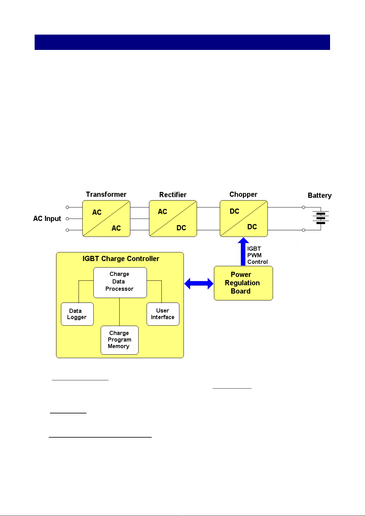
The electrical structure of the MVD charger is represented in the following block
diagram.
The TRANSFORMER reduces the AC input voltage and provides electrical insulation
between the input and the output of the charger. The RECTIFIER converts the AC output
of the transformer to an unregulated DC voltage.
The CHOPPER (operating at high frequency), regulates the output voltage and current to
the desired values. It generates a perfectly constant output current, with negligible ripple.
The IGBT CHARGE CONTROLLER is the main control unit of the MVD.
It's a microprocessor based electronic board, and it contains the USER INTERFACE
(Display, LEDs and Keyboard), the CHARGE PROGRAM MEMORY (where all the
programmed parameters are saved), the DATA LOGGER (where the charge history is
saved) and the CHARGE DATA PROCESSOR, which manages the entire charge
process.

Battery Charger MVD
User's Manual
The POWER REGULATION BOARD controls the operation of all the power components. It
receives command signals from the IGBT CHARGE CONTROLLER, and it generates the high
frequency PWM control signal that drives the IGBT regulator.
The control panel is complete and easy to use: four coloured LEDs indicate the state of the
charge, while a 2x20 character dot matrix display gives complete information and error
messages in plain text (multilingual).
A three button flat membrane keyboard is used for programming and data review.
(OPTIONAL)
For each battery, the user can program the TYPE (Flooded Lead Acid, GEL, AGM),
the CAPACITY (from 5Ah to 2500Ah), the number of Elements and the curve of charging.
The MVD start to charge the curve for the given parameters.
While the programming and operation of the MVD can be done using a simplified and automatic
form, expert users have the possibility to adjust the charge parameters and options without
limits (Temperature Limits, Temperature compensation, Maximum voltage, Cable length and
section for voltage drop cable, Language and much more).
The charging curve of the MVD charger is based on the parameters that the user entry in a
easy menu of a single curve, but instead of applying a defined charge curve to the battery, the
charger calculates all the parameters (Currents, Voltage Limits, Maximum Times) according
with the Battery Data and the User programming.
Moreover, the curve is dynamically adjusted while the charge is in progress, depending on the
real status of the battery.
(OPTIONAL)
It's equipped with a Real-Time Clock, which allows the user to program the desired start time of
the day, the full charge time window and to schedule the weekly equalize cycles.
(OPTIONAL)
The MVD Charger saves the results of the last 250 charge in the built-in data logger.
(OPTIONAL)
In addition, it's possible to connect the charger to the DoctorFleet.com Fleet Management
System, which allows to monitor the complete fleet through a WEB based interface, and to
send automatic messages/reports by email.
MVD-BASSI Page 4 of 34

Battery Charger MVD
User's Manual
3. INSTALLATION
Conditions of use:
•Temperature (operation): from 0°C to 50°C.
•Temperature (storage): from –20°C to 60°C.
•Relative Humidity: less than 75 %.
CONNECTION OF THE AC INPUT
The charger must be connected to the AC input using an adequate cable and plug, with
disconnect switch and fuses.
The AC input wires have to be connected to the AC INPUT TERMINAL BLOCK, that is located
on the internal panel, just under the AC input contactor.
Make sure to tighten the terminal block screws with the proper torque, and pull each wire
separately in order to verify that they are mounted properly.
MVD-BASSI Page 5 of 34

Battery Charger MVD
User's Manual
AC INPUT VOLTAGE SELECTION 208/240 or 480/600 VAC
The three-phase models may be configured for 208/240 VAC or 480 VAC nominal input
voltage.
This selection can be done using the apposite terminal block, that is located at the center of the
internal panel, between the terminal blocks for the AC input wires and the AC contactor.
In addition, it's necessary to adjust the AC input connection of the AUXILIARY
TRANSFORMER to the proper AC input voltage.
•Disconnect the charger from main supply and battery.
•Remove the plastic protection over the AC INPUT VOLTAGE PRESET BOARD
•Remove the three metal bars.
•Place the metal bars in the required position, with ref to the following pictures.
•Tighten the nuts with the proper torque.
•Apply the plastic protection.
•Connect the charger to main supply.
SELECTION BOARD
IN POSITION
208-240 VAC
SELECTION BOARD
IN POSITION
480 VAC
MVD-BASSI Page 6 of 34
ATTENTION!
Remember to set BOTH the three metal bars
AND the input wire on the Auxiliary Transformer.
If one of the two are not set properly, the charger may be damaged.

Battery Charger MVD
User's Manual
4. PROGRAMMING
PRELIMINARY CONTROLS
Before to proceed with the programming sequence and before to connect a battery, make sure
that the MVD charger has been installed by a qualified electrician, according with the
instructions reported in this manual.
Before to use the charger, it's necessary to control that the ventilation slots are not obstructed,
and that all the safety precautions reported in this manual are respected.
STARTUP SEQUENCE
Turn on the charger by moving the main switch to position “1”.
The charger will perform an automatic test of the control circuits, and will wait for a random
delay on start. (ONLY AFTER A BLACK/OUT HAPPENS)
The display will visualize the following messages.
MVD-BASSI Page 7 of 34
SYSTEM READY
MAX xxx V – xxx A
BASSI
CHARGER MVD
SYSTEM CHECK
PLEASE WAIT ...
XX.X V XXXX Ah
EL= XXX PROG.XX

Battery Charger MVD
User's Manual
USER PROGRAMMING MODE
HOW TO ACTIVATE USER PROGRAMMING MODE
•Press the button DOWN and keep it pressed for 3 seconds
The display will show the message:
•Enter the Programming Password. UP DW UP DW UP
The display will show the message:
HOW TO MODIFY A VALUE
•Scroll between the programmable values using the UP/DOWN buttons.
•In order to modify a value, press ENTER and keep it pressed for 2 seconds, until the
cursor will start blinking over the value that can be modified.
•Modify the value using the UP/DOWN buttons.
•Confirm the modified value by pressing ENTER for 2 seconds, until the cursor will
disappear. At this point the new value will be saved.
HOW TO RETURN TO NORMAL MODE
•Press the buttons UP and DOWN simultaneously.
MVD-BASSI Page 8 of 34
ATTENTION!
Before to program the charger, disconnect the battery.
This condition is necessary in order to activate the User Programming Mode.
Only expert users should modify the settings of the charger.
EDIT PASSWORD
MOD. USER

Battery Charger MVD
User's Manual
MENU PRG N. 1 – 8 (1-20 OPTIONAL) : PROGRAM SETTING CURVES
For each program, it's possible set at maximum 6 different STEP, and for each step it's possible
set the TYPE of STEP (current constant, voltage constant, pause cooling), MAXIMUM TIME of
the single STEP (0-65350 minute), CURRENT (constant current or minimum limit current ),
VOLTAGE (maximum voltage or holding voltage).
For each program, the display shows this setup page:
for example:
Press ENTER to modify this particular program:
PROGRAM and STEP INDICATOR-settings
1.A – 1(nr. of program [1..8..20]) A (step of the program [A.B.C.D.E.F])
f.e 2.C (program nr.2 and step C (third))
f.e 5.B (program nr.5 and step B (second))
TYPE of CHARGING CURVES (Programmable values)
I=K – [I=K] current constant
[V=K] voltage constant
[PAU] pause/cooling
MAXIMUM TIME of the SINGLE STEP (Programmable values)
T= 240m [DIS,5,..,65350] - 240minutes after this time the charger close the actual step and will
begin the next step.
CURRENT SETTING/LIMIT (Programmable values)
I=18%Ah [DIS,1,..,99] – for every 100 Ah of the battery capacity the charger put 18 Amps.
If you have a battery of 500 Ah –> 18%Ah = 18 * 5 = 90 Ampere
If you have a battery of 750 Ah –> 25%Ah = 25 * 7.5 = 187.5 Ampere
If you have a battery of 1100 Ah –> 10%Ah = 10 *11 = 110 Ampere
In TYPE of CHARGING CURVES → (I=K) I value is the current costant during this step
In TYPE of CHARGING CURVES → (V=K) I value is the minimum limit of current before to end
this step of program.
VOLTAGE SETTING/LIMIT (Programmable values)
V=2.40 [DIS,2.20,..,2.80] V/Cell – limit voltage for single elements.
In TYPE of CHARGING CURVES → (I=K) V value is the maximum limit of battery voltage
before to end this step of program.
In TYPE of CHARGING CURVES → (V=K) V value, the charger compensation the current to
hold voltage value.
MVD-BASSI Page 9 of 34
1.A I=K T= 240m
I=18%Ah V=2.40 V
PRG N.XX
SETTING

Battery Charger MVD
User's Manual
It's possible to scroll between each programs using the buttons UP/DOWN, and press ENTER
to modify or skip each single parameter.
ERROR SETTING IN CURVE PARAMETER
If the user insert the parameter not correct during the set of internal programs (curves), when
you try to work with this program, the charger don't start and the display show:
You must entry in a menu of this program and check the parameters in errors.
The display show ERROR SETTING even you try to work with a program that are all steps
A,B,C,D,E,F empty.
In this way the PROG NR.1 not work.
MVD--BASSI Page 10 of 34
ERROR
SETTING
1.A PAU T= DIS.
I=DIS. V=DIS.
1.D PAU T= DIS.
I=DIS. V=DIS.
1.B PAU T= DIS.
I=DIS. V=DIS.
1.C PAU T= DIS.
I=DIS. V=DIS.
1.E PAU T= DIS.
I=DIS. V=DIS.
1.F PAU T= DIS.
I=DIS. V=DIS.

Battery Charger MVD
User's Manual
PARAMETER : MAX VOLTAGE
Programmable values: from 2.40 to 3.00 V/Cell, or DISABLED
Default value: 3.00 V/cell
NOTES: This parameter sets a maximum limit for the cell voltage. If this limit is reached, the
charge is terminated and a specific error message is given.
PARAMETER : MAX TEMPERATURE
Programmable values: from (45 to 70 °C) 115 to 160 °F, or DISABLED
Default value: (60 °C) 140 °F
NOTES:This parameter sets a maximum limit for the battery temperature. If this limit is reached,
the charge is terminated and a specific error message is given. This functionality requires the
connection of an optional temperature probe.
PARAMETER : TEMPERATURE COMPENSATION
Programmable values: ENABLE or DISABLED.
Default value: (recommended ENABLE if the temperature probe is installed)
NOTES: When a battery temperature probe (optional) is used, the charger can calculate the
voltage limit dynamically, in order to compensate the effect of the temperature of the
electrolyte.
MVD--BASSI Page 11 of 34
MAX VOLTAGE
3.00 V/el
TEMPERATURE
TOO HIGH

Battery Charger MVD
User's Manual
PARAMETER : CABLE SECTION
Programmable values: from (1 to 250 mm2) or DISABLED.
Default value: section of the installed cable.
NOTES: The charger can calculate the voltage drop in the cable of the battery, in order to
approximate the correct value of the battery voltage.
PARAMETER : CABLE LENGHT
Programmable values: from (20 to 3000 cm) 0.65 to 98.40 ft, or DISABLED.
Default value: lenght of the installed cable.
NOTES: The charger can calculate the voltage drop in the cable of the battery, in order to
approximate the correct value of the battery voltage.
PARAMETER : LANGUAGE
Programmable values: ENGLISH, FRANCAIS, ITALIANO..
Default value:
NOTES: The language of the display.
(OPTIONAL) PARAMETER : DATE and TIME
Programmable values: Month/Day/Year, Hour/Minutes
Default value: *****
NOTE:It's fundamental to keep the Real Time Clock set to the correct date and time, in order to
use all the time base functions. The Charger calculates the Day of the Week automatically,
however it's necessary to adjust the Clock manually in Daylight saving time periods.
MVD-BASSI Page 12 of 34

Battery Charger MVD
User's Manual
(OPTIONAL) PARAMETER : WIRED NET / TEST WIRELESS / LOCAL USB
NOTE:
This is an advanced function, described on the MVD “ADVANCED PROGRAMMING
MANUAL”.
It's used when the charger is equipped with a Communication Card to the fleet management
system DoctorFleet.com, or when it's equipped with an Expanded Data-Logger Card with USB
connection.
MVD-BASSI Page 13 of 34

Battery Charger MVD
User's Manual
5. PROGRAM EXAMPLES
PROGRAM CURVE : IUIa
Using this Program for the follow battery: reading battery voltage 24.7 V
Press the buttons UP and DOWN simultaneously.
MVD-BASSI Page 14 of 34
1.A I=K T= 480m
I=18%Ah V=2.40 V
1.B V=K T= 240m
I=5%Ah V=2.40 V
1.C I=K T= 180m
I=5%Ah V=2.65 V
1.F PAU T= DIS.
I=DIS. V=DIS.
1.E PAU T= DIS.
I=DIS. V=DIS.
1.D PAU T= DIS.
I= DIS. V= DIS.
24.7 V 500 Ah
EL= 12 PROG.01

Battery Charger MVD
User's Manual
In the first step A (1.A) , the charger workes in current costant way (I=K) for the maximum time
of (480 minutes) with a current of (18%Ah --> [500 Ah] 5*18 = 90 Amp), and if the battery
voltage reache (2.40 V/Cell) before the end of the time, the charger will go to next step.
In the second step B (1.B) , the charger workes in voltage costant way (V=K) for the maximum
time of (240 minutes) and compensation the current for hold the battery to (2.40 V/Cell), and if
the current go down until (5%Ah --> [500 Ah] 5*5 = 25 Amp), before the end of the time, the
charger will go to next step.
In the first step C (1.C) , the charger workes in current costant way (I=K) for the maximum time
of (180 minutes) with a current of (5%Ah --> [500 Ah] 5*5 = 25 Amp), and if the battery
voltage reache (2.65 V/Cell) before the end of the time, the charger will go to next step.
Steps (1.D), (1.E), (1.F) are empty, the charger jump this state and finisch the cycle.
MVD-BASSI Page 15 of 34

Battery Charger MVD
User's Manual
PROGRAM CURVE : IU1 U2
Using this Program for the follow battery: reading battery voltage 39.6 V
Press the buttons UP and DOWN simultaneously.
In the first step A (3.A) , the charger workes in current costant way (I=K) for the maximum time
of (200 minutes) with a current of (25%Ah --> [800 Ah] 8*25 = 200 Amp), and if the battery
voltage reache (2.40 V/Cell) before the end of the time, the charger will go to next step.
MVD-BASSI Page 16 of 34
3.A I=K T= 200m
I=25%Ah V=2.40 V
3.B V=K T= 240m
I=3%Ah V=2.40 V
3.C V=K T=FULL
I=DIS V=2.25 V
3.D PAU T= DIS.
I= DIS. V= DIS.
3.E PAU T= DIS.
I= DIS. V= DIS.
3.F PAU T= DIS.
I= DIS. V= DIS.
39.6 V 800 Ah
EL= 18 PROG.03

Battery Charger MVD
User's Manual
In the second step B (3.B) , the charger workes in voltage costant way (V=K) for the maximum
time of (240 minutes) and compensation the current for hold the battery to (2.40 V/Cell), and if
the current go down until (3%Ah --> [800 Ah] 8*3 = 24 Amp), before the end of the time, the
charger will go to next step.
In the third step C (3.C) , the charger workes in voltage costant way (V=K) for ever (FULL) and
compensation the current for hold the battery to (2.25 V/Cell).
Steps (3.D), (3.E), (3.F) are empty, the charger jump this state and finisch the cycle.
MVD-BASSI Page 17 of 34

Battery Charger MVD
User's Manual
PROGRAM CURVE : I1 + I2 +I3 + I4 + I5 +I6
Using this Program for the follow battery: reading battery voltage 0.0 V
Press the buttons UP and DOWN simultaneously.
In the first step A (8.A) , the charger workes in current costant way (I=K) for the maximum time
of (60 minutes) with a current of (15%Ah --> [600 Ah] 6*15 = 90 Amp).
In the first step B (8.B) , the charger workes in current costant way (I=K) for the maximum time
of (120 minutes) with a current of (20%Ah --> [600 Ah] 6*20 = 120 Amp).
In the first step C (8.C) , the charger workes in current costant way (I=K) for the maximum time
of (180 minutes) with a current of (25%Ah --> [600 Ah] 6*25 = 150 Amp), and if the battery
voltage reache (2.40 V/Cell) before the end of the time, the charger will go to next step.
In the first step D (8.D) , the charger workes in current costant way (I=K) for the maximum time
MVD-BASSI Page 18 of 34
8.A I=K T= 60m
I=15%Ah V=DIS
8.B I=K T= 120m
I=20%Ah V=DIS
8.C I=K T= 180m
I=25%Ah V=2.40
8.D I=K T= 240m
I=15%Ah V=2.60 V
8.E I=K T= 120m
I=10%Ah V=DIS
8.F I=K T= 120m
I=5%Ah V=DIS
0.0 V 600 Ah
EL= 24 PROG.08

Battery Charger MVD
User's Manual
of (240 minutes) with a current of (15%Ah --> [600 Ah] 6*15 = 90 Amp), and if the battery
voltage reache (2.60 V/Cell) before the end of the time, the charger will go to next step.
In the first step E (8.E) , the charger workes in current costant way (I=K) for the maximum time
of (120 minutes) with a current of (10%Ah --> [600 Ah] 6*10 = 60 Amp).
In the first step F (8.F) , the charger workes in current costant way (I=K) for the maximum time
of (120 minutes) with a current of (5%Ah --> [600 Ah] 6*5 = 30 Amp).
MVD-BASSI Page 19 of 34

Battery Charger MVD
User's Manual
PROGRAM CURVE : Voltage Refresh
….......
Using this Program for the follow battery: reading battery voltage 83.0 V
Press the buttons UP and DOWN simultaneously.
In the first step A (6.A) , the charger workes in voltage costant way (V=K) for ever (FULL) and
compensation the current for hold the battery to (2.25 V/Cell). During this step not exist
any limits of current and MVD can work until the maximum current.
Steps (6.B), … , (6.F) are empty.
MVD-BASSI Page 20 of 34
83.0 V 1200 Ah
EL= 40 PROG.06
6.B PAU T= DIS.
I= DIS. V= DIS.
6.F PAU T= DIS.
I= DIS. V= DIS.
6.A V=K T= FULL
I=DIS. V=2.25
Table of contents
Other Bassi Batteries Charger manuals


