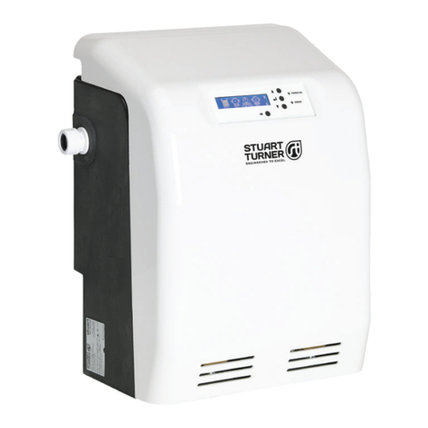
Stuart Turner AQUABOOST User manual

AQUABOOST
MAB O&M MANUAL
Please note images are representative only and may not
portray your model

2
content page
1. general information about the pump regulator 3
2. safety and warning
instructions
3
3. pump controller 4
4. electrical connection 5
5. first switch on - Initial
setup
7
6. panel description 8
7. clock, GSM, SD-card
setting
10
8. menu operation 11
9. set points menu 12
10.times menu 12
11.message menu 13
12.safety menu 14
13.transducer menu 16
14.pump / motor menu 17
15.controller menu 18
16.communication menu / phone book 18
17.system setting 20
18.cabinet setting 21
19.clear memory 22
20.pump change 22
21.zero flow shut-off 22
22.MAB Modbus register 23
23.error list 24
24.SMS commands 26
25.transducer connection 4-20mA (DST) 26
26.customer settings 26
27.Technical structure of the MAB control 27
Instruction manual
Execution: pressure
Type: MAB S-No.:
System controller for 1- 3 pumps Software version
1.00 (xxx) Stand 18.12.2020
MAT
bar
aktiv
RESET
MAT
Execution:
pressure control
pressure switch
limit control
limit switch
level control
level switch
temperature
controller
temperature switch
volume regulator
fluid flow regulator
vacuum regulator
Option:
RS485 Modus / GSM
Inverter:
E600 0,75-5,5kW

3
1. General information about the pump regulator
This product complies with the latest technology and is constantly being developed and improved. The device has
undergone extensive testing after manufacture and therefore functions flawlessly. To ensure optimum function, read and
observe this operating manual.
2.Safety and warning instructions
Before installing and commissioning the pump regulators, please read these operating instructions carefully and observe
all warning and safety instructions. Always keep this manual in easy reach near the pump regulator.
Definition
Warning !
Failure to observe the safety instructions can result in serious or even life-threatening bodily injury or
substantial material damage!
Caution !
Failure to follow these instructions can result in serious or life-threatening bodily injury or material damage!
Notice !
Failure to follow these instructions may cause malfunction of the system!
The pump controller works with dangerous electrical voltages and controls dangerous rotating mechanical
parts. The installation, commissioning and maintenance of this system may only be carried out by qualified
personnel who are familiar with the operation. Be especially careful when automatic restart is activated. To
prevent injuries due to possibly uncontrolled restarting of the motors after power failure, deactivate the
automatic restart in case of doubt. During repairs or maintenance work, make sure that the system can not be
switched on again by others! The built-in frequency converters have capacitors that carry dangerous high
voltage even after switching off the power supply. Therefore wait at least 5 minutes after switching off the
mains voltage before working on the device. Care must be taken that no live parts are touched.
Do not work on the controller,
when mains voltage is applied. Earth the motors at the connections provided for this purpose.
If the provisions of the regional energy suppliers require a residual current device, it must
the on-site RCCB for frequency converter operation is an all-current sensitive / selective RCD (RCD)
circuit breaker type: B, B + with rated current 300mA.
Make sure that the input voltage matches the voltage entered on the nameplate. All pump regulators are tested
for dielectric strength and insulation resistance. Before the insulation measurement on the pump system, z.
E.g. during the inspection, the pump controller and the sensors must be disconnected!
The regulations of the electrical installation and the regional energy suppliers must be observed!
Environmental influences such as high temperatures, high humidity are to be avoided as well as dust, dirt and
aggressive gases. The installation site should be well ventilated, not exposed to direct sunlight. Do not apply
mains voltage to the sensor terminals or to the control terminals. Enter the operating signals Manual / 0 / Auto
via the selector switch or via the control of the external contacts and not by switching on or off a mains or
motor contactor. To ensure that your control system operates safely and reliably, all relevant safety
regulations, such as: B. accident prevention regulations, regulations, VDE regulations, etc. are observed.
Since these regulations are handled differently in the German-speaking countries, the user must observe the
respective conditions applicable to him. The manufacturer can not exempt the user from the obligation to
follow the latest safety regulations
The technical data and descriptions in this manual have been prepared to the best of our knowledge and
belief. However, product enhancements are ongoing, so the manufacturer reserves the right to make such
changes without notice. The manufacturer can not be held liable for errors in the operating instructions.
Warranty is provided within the Federal Republic of Germany and within the statutory warranty period and
applies only to the product itself and not for any consequential damage or damage or cost incurred by the
occurrence of a warranty claim to others. Plants or system parts arise. The operator must in any case ensure
that a failure or defect of the product can not lead to further damage.

4
3. Pump controller
This pump controller works as pressure controller fully automatically, depending on demand.
The speed of the pump (s) is infinitely variable with frequency converter operation. The actual value in the system is
determined by means of a sensor. A PI controller adjusts the actual value to the setpoint. When operating with contactor
or soft starter, the pump (s) are switched on and off as required. The pump controller can be parameterized and must be
adapted to the respective operating conditions. The parameters are displayed in plain text.
Commissioning is menu-driven. During commissioning, some data must be entered to ensure smooth operation of the
system. It should be done by a knowledgeable person.
Advantages of pump control
-almost constant control value
-Continuous adjustment of pump performance to changing operating conditions
-Energy saving in frequency converter operation
-no integrated memory required for frequency converter operation
-less mechanical wear of the pumps
Design of the pump regulation
-the pump (s) must be designed according to the plant / requirement
-the integrating memory must be properly sized and set correctly.
-The pump (s) must have hydraulic capacity (s) of 10 - 20% in order to be able to control.
-For submersible pumps, the minimum frequency must be limited to 30..35Hz
(Hydrodynamic bearing) (See information from the manufacturer of the engine.
-For underwater pumps a power reduction of approx. 5..10% can be assumed
Use of GSM monitoring
If you have installed a GSM modem (terminal), you can monitor the pump controller.
Depending on the technical design, different commands are available to you.
Make sure the antenna is well aligned for proper wireless network connection.
Make sure that the power supply is always active together with the pump regulator.
You need a registered SIM card. There are 3 users allowed as phonebook entry.
Use of a Modbus data transfer
If you have installed the Modus interface, you can monitor the pump controller or query data in the registers. Depending
on the technical design, different data is available to you. You can reset the controller via the Modbus interface. There is
no remote adjustment. Make sure that the power supply is always active together with the pump controller.
Installation and assembly of the controllers
Environmental influences such as high temperatures, high humidity are to be avoided as well as dust,
Dirt and aggressive gases. The installation site should be a well-ventilated place not exposed to direct sunlight.
Due to the heat convection, the frequency converter controller must have at least
Cm15 cm away from side walls or other facilities.
The permissible temperature range of + 5 ° C to + 30 ° C must not be fallen below or exceeded.
Do not install the frequency converter controller near heat radiating equipment
Assembly of the pump control
Depending on the design of the control, a metal wall cupboard or a metal cupboard is built.
The wall cabinet has 4 holes for wall mounting the control cabinet.
For sole mounting stud bolts are recommended on which the control cabinet is hung.
Mounting dimensions: See manufacturer data sheet ... .
The cupboard is delivered and set up with 200mm base.
Pay attention to a secure position and ensure good ventilation on site.
Mounting dimensions: See manufacturer data sheet ... .
Construction of a control system with integrated storage tank (expansion tank)
A back flow preventer with spring force is absolutely necessary and can be installed in the suction line in front of the
pump or in the pressure line behind the pump! If the check valve is installed in the suction line, an expansion vessel must
be installed on the pressure side. Otherwise, an expansion tank can be installed if necessary.
the system is operated with an expansion vessel, the expansion vessel must be pre-pressed in the unpressurised state. The
prepress pressure must be checked regularly.

5
The height of the prepress pressure is approx. : start pressure minus 0.50 bar
Environmental conditions:
Ambient temperature: + 5 ° C - + 35 ° C
Humidity: 0- 95% non-condensing
Altitude: 1000m, 1% reduction / 100m
Vibration: maximum 0.5g
Type of protection: see type plate
Technical data: see type plate
Construction of a pump system
A back flow preventer is mandatory and can be placed in the suction line in front of the pump or in the
Pressure line to be installed behind the pump! If the back flow preventer is installed in the suction line, an
integrated storage tank is required. Otherwise install an expansion vessel as required.
Examples:
Operation of the pump system with integrated storage tank (expansion vessel)
If the system is operated with an integrated storage tank, the integrating storage tank must be pre-pressed in the
unpressurised state. The prepress pressure must be checked regularly.
The height of the prepress pressure is: Starting pressure minus 0.50 bar.
Example: set start pressure: 4.00 bar
pre-press integrating storage to: 3.50 bar
Booster systems (DEA)
Booster systems are fully cased and wired pumping systems. With them, the installation effort is minimal -
connection to the existing pipe network, mains voltage and commissioning. The controller is set at the factory
for these systems. These operating instructions refer only to the electrical control of the system, therefore, if
necessary, consult the operating instructions of the pump (s).
4. Electrical connection of the controller
Make sure that the input voltage is on the nameplate
registered voltage corresponds. Be sure to observe the supply voltage and terminal assignment!
The installation, commissioning and maintenance of the drives may only be carried out by
a person skilled in the art of pumping.
Use shielded cable! Connect the shield to the earthing clamps in the control cabinet and to the pump!
For submersible motor pumps, connect the shield to ground potential near the pump.
Do not apply mains voltage to the sensor or control terminals.
Do not manipulate the sensor signal!
Do not connect other consumers to the 24V supply!
The used sensor 4..20mA, is connected to the respective terminals!
The respective pin assignment can be found in the wiring diagram.
All pump regulators use 4..20mA sensors.
The pin assignment can be found in the wiring diagram.
If the motor cable is longer than 50 meters, it is recommended to install a motor choke / sine filter.
Check the correct connection of the mains, sensor and control cables.
1flow direction
2
regulator
3
Motor
4pump
5 back flow preventer
6 pressure sensor
7
expansion vessel
8template tank

6
Set motor protection
The pump controller has a monitoring function for the motor current. The motor rated current when
frequency converter operation is set in the menu. For designs with soft starter or contactor, the rated motor
current is set on the motor protection relay or on the soft starter. See the respective operating instructions
which are always enclosed with the documents.
Cable connection
The cable to the motor, the sensor cable and the cables for the external contacts must be provided with
shielded cable (80%) and connected to the shielding brackets according to the opposite principle. If EMC
cable glands are used, they must be connected to the screen according to the manufacturer's instructions.
Only with proper installation of the screen, a trouble-free operation is guaranteed!
Umbrellas and earth are two different connections. Never use the shield as a grounding!
connection example with shield bracket.
power connection
The pump regulators have a mains connection of 230 / 400V 50 / 60Hz or 230V 50 / 60Hz.
See type plate of the pump regulator. Operating the controller with / without RCCB is of
depending on the respective regulations. The protection takes place with fuses of characteristic C.
The size of the fuse can be found on the rating plate of the pump regulator.
Digital inputs pump controller
Depending on the versions, different numbers of digital inputs are available. The digital inputs have their own potential
with reference to "CO". It is used low voltage. When transferring signals from external systems, the potential must be
disconnected via a relay contact. The digital inputs can be set as normally closed or normally open in the "Messages"
menu and can be assigned different functions. Each function except "Reset" can only be assigned once. Functions see
menu "Messages"
Digital outputs pump controller
Depending on the versions, different numbers of digital outputs are available. The digital outputs with orange terminals
are floating relay outputs. The outputs may be charged with 24VDC-1A or 230VAC-1A.
For signal transmission on external systems with high power, the potential must be implemented via a relay. The digital
outputs can be set as normally closed or normally open in the "Messages" menu and can be assigned different functions.
Each function can only be assigned once. If the total power of the controller is greater than 5.4kW, output 98 / N is
always blocked for the panel fan. Functions see menu "Messages"
Digital frequency inverter outputs
For controllers with frequency inverters, depending on the version, there are different numbers of converter relays
available. These relay outputs are not always routed to the terminal block. The inverter relays are potential-free and may
be charged with 24VDC-1A or 230VAC-1A. For signal transmission to external systems with high power, the signal
must be implemented via a relay. The inverter relays can be set as normally closed or normally open in the "Messages"
menu and can be assigned different functions. Each function can only be assigned once. Functions see menu
"Messages"
Analog inputs (transducer)
Depending on the versions, different numbers of sensor inputs are available. The analog inputs have their own potential.
The signal is always 4-20mA. Only passive sensors with 24VDC supply can be used. If active sensors are to be used,
our converter "HO.xx" must be used. For long sensor lines or for signal transfer from external systems, the signal must
be disconnected via a potential converter. Each function can only be assigned once. Functions see menu "Basic" +
"Sensor"
motor connection
The motor must be connected according to the output voltage. See type plate of the pump regulator. Clamp
the motor on star or triangle. See nameplate of the engine. The direction of rotation of the motor determines
the frequency converter. Direction of rotation can be set in the "Motor" menu.
For controls with soft starter or contactor, the direction of rotation must be adjusted by reconnecting.
Depending on the design of the control, PTC thermistors can be connected.
Before switching on the mains voltage again check all connections for correctness!

7
V1.xx (xx.x)
MAT
▲
▼
SN. xxxxx
MAB
00,18 bar
off
off
off
P1
P2
P3
P1:□□□□□ 000Hz, 00,0A
P2:□□□□□
000Hz,
00,0A
P3:□□□□□ 000Hz, 00,0A
Init: (2 FU)
FU 1 : OK, old
FU 2 : OK, new
Init: (2 FU)
FU 1 : OK, old
FU 2 :
OK, old
5. First switch on - Initial setup
Example: double system
At power-up, the controller initializes Main display after initialization
> >
If the initialization goes wrong, there is an error message. With ER101 the frequency inverters can not be
reached. Check the Modbus connection / mains voltage of the frequency inverter.
Main display error ER ....
The system is now set to "AW" = active change.
If the system setting is to be changed, this must be done in the base menu.
5.1 Switching on the system after changing the frequency inverter
Example: Double system with new INV 2
At power-up, the controller initializes
> >
Attention ! Confirm within 20s, otherwise the frequency converter will not be parameterized!
>
Confirm the factory setting with the "Set" button
Main display after commissioning.
V1.xx (xx.x)
MAT
▲
▼
SN. xxxxx
MAB
00,18 bar
off
off
off
P1
P2
P3
P1:□□□□□ 000Hz, 00,0A
P2:□□□□□
000Hz,
00,0A
P3:□□□□□ 000Hz, 00,0A
OK !
INV 2 : factory setting ?
.........
......
SET
INV 2 : factory setting ?
.........
......
00,18 bar
ER101 P1
ER101 P2
ER101 P3
P1: FU ERR
P2:
FU
ERR
P3: FU ERR

8
6. Panel description
Control panel with four -line LCD display for parameters and operating data:
The backlight can be switched off with a delay.
The arrow keys
Select the functions (scrolling),
Enter / change data.
The SET / RESET - keys
Storing input data,
Error acknowledgment
Display with different symbols and values
Active main display with "external" / "internal" set point specification status
On the idle page, symbols show whether GSM or Modbus is used.
operating displays
Display: status, pressure, speed, current or active / inactive
Pumps off Manual operation (Hand) Automatic operation (Auto)
Select operating displays
With the ▲ arrow key, the next screen is displayed.
Pressing the same arrow key the next screen is displayed.
Use the ▼ arrow key, the previous screen is displayed.
If the display is "hours of operation" is displayed and the ▲arrow key is pressed, so you get to the error
memory.
From the fault memory of the SET / RESET button must be pressed to return to the initial display.
active messages
Operating Status: time, pressure, frequency, current P1-xx ... , equipment temperature
MAT
▲
▼
05.18 bar
Automatic active
MAT
▲
▼
05.18 bar
05.23 bar
Automatic active
16.09. 14:20
08,25 bar
Automatic active
05.18 bar
00,18 bar
13:48:32
Hand P1
Hand P2
Hand P3
P1:■■■□□ 030Hz, 07,0A
P2:■■■□□
030Hz,
07,1A
P3:■■■□□ 030Hz, 06,9A
04,74 bar
13:48:32
off
off
off
P1
P2
P3
P1:□□□□□ 000Hz, 00,0A
P2:□□□□□
000Hz,
00,0A
P3:□□□□□ 000Hz, 00,0A
08,25 bar
13:48:32
Auto P1
Auto P2
Auto P3
P1:■■■■□ 036Hz, 07,0A
P2:■■■■■
050Hz,
09,5A
P3:□□□□□ 000Hz, 00,0A
08,25 bar
13:48:32
Auto
Auto
Auto
P1
P2
P3
P1:■■■■□ 036Hz, 07,0A
P2:■■■■■
050Hz,
09,5A
P3:□□□□□ 000Hz, 00,0A
08,25 bar
08,31 bar
Auto
Auto
Auto
P1
P2
P3
P1:■■■■□ 036Hz, 07,0A
P2:■■■■■
050Hz,
09,5A
P3:□□□□□ 000Hz, 00,0A
08,25 bar
05.01.21
Auto
Auto
Auto
P1
P2
P3
P1:■■■■□ 036Hz, 07,0A
P2:■■■■■
050Hz,
09,5A
P3:□□□□□ 000Hz, 00,0A

9
Messages
Memory status: Hour meter BST: P1-Px Memory status: day run - counter TLZ: P1-Px
Fault memory: 1 - x with date stamp for the last 1-16 error. For each error, the pressure and pump status are
stored on an extra page. Switch over by pressing the SET button for 10 seconds
Information displays
External off
The MA controller is connected via an external input. If the connection is open, the message "External off" appears.
The respective pump (s) are stopped. The alarm relay is not activated
External low water
The MA controller is connected via an external input. If the connection is open, the message "low water" will appear.
The respective pump (s) are stopped. The alarm relay switches.
Fill mode in active
If the "under-pressure" to be active, the MA-regulator is operated in fill mode until the pressure for the first time is
balanced. The alarm relay is not activated.
Safety start active
If the function "Safe Start" to be selected, the MAR controller is operated in fill mode. The master pump is active.
The slave pump (s) is inactive. The alarm relay is not activated.
Top pressure
The current pressure is above the set upper pressure. The MA controller controls off to prevent a further rise in pressure.
It appears the message "top pressure“. The alarm relay is not activated.
Stopped unit
The MA-controller is connected via an external emergency stop. It appears the message "Stopped unit". The pump (s)
are stopped. The red LED lights. The alarm relay switches. "Restart" via GSM or reset - function.
08,25 bar
13:48:32
Auto
Auto
Auto
P1
P2
P3
P1:DF 72-50 LF 065-75 29C
P2:DF
99-50 LF 105-75 45C
P3:DF 00-50 LF 000-75 25C
— Operating hours counter—
BST P1 000:00:00 - S 000
BST P2 000:00:00 - S 000
BST P3 000:00:00 - S 000
TLZ P1 1 000:00:00 - S 000
TLZ P2 1 000:00:00 - S 000
TLZ P3 1 000:00:00 - S 000
Reset . . . . . . . .
——Fault memory————-
ER001 15-01-13 13:59
ER004 16-01-13 11:59
———————
———————
———————
———————
Reset . . . . . . . .
external —
off —
—
low —
water —
in 30s —
fill mode—
active —
—
Safety —
Start —
active —
top
—
pressure —
for 30s —
stopped —
unit —
—

10
01.2021 off
2:45 off
□□□□ 000Hz,
00,0A
al: 20 off
25€
off
□□□□ 000Hz,
00,0A
——-SD-card————
erval :
1 Min
a: 1 .csv / 11
: active frei : 3,8 GB
. . . . . . . .
d: 19200 off
inactive off
□□□□□ 000Hz,
00,0A
7. Clock, GSM, SD-Card, Modbus set
Set time / date:
Press the SET / RESET button on the respective side.
Data Set and save with the help of the arrow ▲key, arrow ▼key and the SET / RESET key.
Set GSM users:
Press the SET / RESET button on the respective side.
Data Set and save with the help of the arrow ▲key, arrow ▼key and the SET / RESET key.
Set SD card:
Press the SET / RESET button on the respective side.
Data Set and save with the help of the arrow ▲key, arrow ▼key and the SET / RESET key.
SD card messages:
Data rate: 1 min: min / 10 min / 1 hour / 10 sec.
Specification: 1/15 0 (display example)
1 / = Current file to be written to
15 = number of data written in the current file
0 = number of incorrect data
SD: Err.card (display example)
message: SD: none: no SD card inserted
message: SD: active: data is being written
message: SD: active + full: data will be overwritten
message: SD: inactive: data are not written
message: SD: Err. Card: SD card defective
message: SD: format: no DS card inserted
File: 1.csv file name and file format for evaluation in Numbers (MAC) or Excel (Microsoft)
*Set Modbus slave:
Press the SET / RESET button on the respective side.
Data Set and save with the help of the arrow ▲key, arrow ▼key and the SET / RESET key. .
Between the displays operation can be changed with the arrow keys ▲and ▼
Monday
10.01.2021
14:52:45
off
off
off
P1
P2
P3
P1:□□□□□ 000Hz, 00,0A
Monday
10.
14:5
time
off P1
P2
: 14:53
Su / Wi
: off
P3
P1:□ —————————————
Set .
save
: no
date : 11.01.21
Monday
11.01.2021
14:52:45
off
off
off
P1
P2
P3
P1:□□□□□ 000Hz, 00,0A
GSM: active off
signal:
20 off
15,25€ off
P1
P2
P3
P1:□□□□□ 000Hz, 00,0A
GSM: active off P1
sign user 1 : on
15, user 2
P2
P3
user 3
: off
: off
P1:□ user 4 : on
Set . —————————————
save
: no
GSM: active off
signal:
20 off
15,25€ off
P1
P2
P3
P1:□□□□□ 000Hz, 00,0A
———-SD-card————-
interval : 1 Min
data: 1 .csv / 11
SD: active frei : 3,8 GB
—
int remove SD-card : off
-
dat log-Interval :1 Min
*save data
: on
SD
—————————————
Set save
: no
———-SD-card————-
interval : 1 Min
data: 1 .csv / 11
SD: active frei : 3,8 GB
Address: 001 off
Baud:
19200 off
Bus inactive off
P1
P2
P3
P1:□□□□□ 000Hz, 00,0A
Address: 001 off P1
Bau
Modbus RTU : on
Bus set address: 001
P2
P3
P1:
set baud rate : 19200
Set
—————————————
save
: no
Address: 001 off
Baud:
19200 off
Bus inactive off
P1
P2
P3
P1:□□□□□ 000Hz, 00,0A

11
8. Menu operating
Set and save values
(Example set points)
setpoint
: 03,90bar
start difference : 00,50bar
overrun time
: 5s
———————————
—
save : no
setpoint
: 03,90bar
start difference : 00,50bar
overrun time
: 5s
———————————
—
save : no
setpoint
: 03,90bar
start difference : 00,50bar
overrun time
: 5s
———————————
—
save : Nein
setpoint
: 03,90bar
start difference : 00,50bar
overrun time
: 5s
———————————
—
save : no
setpoint
: 03,90bar
start difference : 00,50bar
overrun time
: 5s
———————————
—
save : no
setpoint
: 03,90bar
start difference : 00,50bar
overrun time
: 5s
———————————
—
save
: Yes
(save parameters)
Start difference : 00,50bar
overrun time : 5s
————————————
save : no
setpoint : 03,00bar
start difference : 00,50bar
overrun time : 5s
————————————
save : no
setpoint : 03,00bar
setpoint
: 03,90bar
start difference : 00,50bar
overrun time
: 5s
———————————
—
save : no
5 seconds, the menu can be
interrupted.
Password code: xxx
Parameter:
xx.xx bar
save: Yes / No
- button for
By pressing the
setpoints Code: 174
times Code: 174
messages Code: 174
safety Code: 174
transducer Code: 174
pump/Motor Code: 174
controller Code: 174
safety Code: 174
communication Code:
815
system setting Code:
815
cabinet setting Code:
815
adjust cabinet
Code: xxx
*Quick
setting
Code: xxx
password : xxx
(enter the password)
setpoints
times
messages
safety
transducer
pump/motor
controller
communication
system setting
cabinet setting
*Quick setting

12
9. Adjust set-points
set points
Explanation of parameters:
Enter the set point which the system should work.
set point :03,00bar - 0,01bar - 99,99bar
Enter the start difference value at which the system will start again after the "Standby"
start difference :00,50bar - 0,01bar - 99,99bar
Enter the differential value at which the next pump will be switched on.
differential value :00,20bar - 0,01bar - 99,99bar
Enter the delay time until the pump to stop.
overrun time :5s - 0s - 999s
10. adjust times
times
Explanation of parameters:
If necessary, select the pressure reduction for the pump on time.
This function gives you the possibility to reduce the energy consumption of the pump.
reduction
:0%
- 0 - 100 % / 0=off
reduction time on
:xx:xx h
- 00:00 - 23:59 h
reduction time off
:xx:xx h
- 00:00 - 23:59 h
Select the test run (e.g., fire extinguishing) for the pump. This feature gives you the option of running the pump once a
day at hand frequency in 24 hours. This function can prevent the pump from seizing.
test time
:10:00h
- 00:00 - 23:59 h
duration
:20s
- 0 - 9999s with manual frequency
test Interval
:0 days
- 0 - 30 days (0 days = Off)
The set-points are set for
the plant.
The times are set for the
plant.
setpoint : 03,00bar
start difference : 00,50bar
overrun time : 5s
setpoint : 03,00bar
start
difference. :
00,50bar
differential value : 00,20bar
overrun time : 5s
setpoint
: 03,00bar
start difference : 00,50bar
differential
value : 00,20bar
overrun time : 5s
setpoint 1
: 03,00bar
start difference 1 : 00,50bar
setpoint 2
:
04,00bar
start
difference 2 :
00,50bar
differential
value : 00,20bar
overrun time :5s
reduction
reduction
time
on
reduction time off
: 0%
: 20:00h
: 23:00h
test time
duration
test interval
: 10:00h
:
20s
: 0 days

13
1-CO-04 :
EAS
2-CO-05 :
WMS
V1
- 01-02 :
FAS
V2
- 11-12 :
FAS
V3- 21-22 :
FAS
1-CO-04 :
EAS
2
-CO-05 :
WMS
- 01-02 :
FAS
- 11-12 :
FAS
- 21-22 :
FAS
2-CO-05 :
WMS
- 01-02 :
ALS
- 11-12 :
ALS
- 21-22 :
ALS
2-CO-05 :
WMS
V1
- 01-02 :
ALS
V2
- 11-12 :
ALS
V3- 21-22 :
ALS
11. adjust messages
messages
Explanation of parameters:
digital inputs 1- 2: ( 4, 5)
The digital inputs are adjustable.
external inputs :xxx - no function
external inputs :S1S - setpoint 1+2
external inputs :WMS /WMO - low water (shutdown with restart)
external inputs :TRS /TRO - dry run (Switch off, restart after reset)
external inputs :HWS /HWO - high level warning without stopping the unit.
external inputs :EAS /EAO - external on / off
external inputs :RSS /RSO - reset
external inputs :SMS /SMO - flow shortage
external inputs :NAO /NAS - Emergency stop, shutdown without restart, no SMS reset possible.
inverter relays:
(INVx)
(1 / 2, 11 / 12, 21 / 22)
The alarm relay frequency converter (INV) 1 to frequency converter X is adjustable.
(See frequency converter terminals)
relay INVx
: xxx
- no function (free setting directly at the INV drive)
relay INVx
:ALS / ALO
- global Alarm (NO / NC)
relay INVx
:FAS / FAO
- local Alarm
relay INVx
:WMS /WMO
- low water
relay INVx
:TRS / TRO
- dry run
relay INVx
:DMS / DMO
- low pressure
relay INVx
:HWS
- high level warning
relay INVx
:SMS / SMO
- flow shortage
relay INVx
:BES / BEO
- operating signal global
relay INVx
:LAS / LAO
- Run signal per pump
IN01-CO-04 : EAS
IN02-CO-05
:
WMS
INV1- 01-02 : ALS
INV2- 11-12 : ALS
INV3- 21-22 :
ALS
⏎
IN0
IN0
IN2-CO-04 : WMS
————————
name: low water
INV1 ————————
INV2 signal NO/NC : NO
INV3 delay on
: 005s
delay off
: 005s
—————————————
save : no
IN0 IN2-CO-04 : WMS
IN0
————————
name: low water
IN
IN
IN
————————
signal NO/NC
delay on
: NO
: 005s
delay off
: 005s
—————————————
save : no
IN01-CO-04 : EAS
IN02-CO-05
:
WMS
INV1- 01-02 : ALS
INV2- 11-12 : ALS
INV3- 21-22 : ALS
⏎
IN01-CO-04 : EAS
IN0
INV2-11-12 : ALS
INV1 ——————————
name: global alarm
INV2 ——————————
INV3 signal NO/NC : NO
—————————————
save : no
IN01-CO-04 : EAS
IN0
INV2-11-12 : ALS
——————————
IN
name: global alarm
IN ——————————
IN
signal NO/NC
: NO
—————————————
save : no

14
o reset :
of
e start :
of
ernal on/off : o
h level digital :
of
run digital : o
water digital :
of
flow digital :
o reset : of
start : of
ernal on/off :
on
h level digital : of
run digital :
on
water digital : of
flow digital : of
oint guard :
on
mps
guardian : of
age guard : of
ime guard : of
12. Setting the safety
Set the safety functions for the system
Explanation of parameters:
Enter the sensor limit value at which the system should switch off.
If the limits are "Off", the sensor (s) are no longer monitored for <or> 20mA.
sensor limit S1
:on
- off / on
lower limit
:on
- off / on
upper limit
:on
- off / on
sensor limit S2
:off
- off / on
lower limit
:off
- off / on
upper limit
:off
- off / on
delay
:30s
- 1s - 99s
Select the reset function. In the event of a fault, this function enables an automatic
restart to be started 3 times within 20 minutes.
auto reset
:off
- off / on
number of reset / 20 min
:04
- 1 - 99
delay
:30s
- 1s - 99s
If the safe start function is switched on, the
Mains voltage to fill the pipeline slowly and gently. Only one works in safe start
Fixed speed pump for the set time. The next pump (s) is (are) stopped.
safe start
:on
- off / on
save time
:09min
- 1min - 99min
safe frequency
:40Hz
- 0 -200Hz
Set the digital extern on/ off function. If the corresponding digital input is activated,
is switched off to „ extern on/off. automatic restart is preset!
Assignment of the digital inputs is done is menu.
extern on/off Hand
:on
- off / on
extern on/off Auto
:on
- off / on
message
:yes
- no / yes
warning :no - no / yes
error :no - no / yes
restart :no - no / yes
SMS :off - off / on
Set the digital dry run protection. If the corresponding digital input is activated,
is switched off to "dry run". No automatic restart is preset!
Assignment of the digital inputs is done is menu.
dry run digital Hand :off - off / on
dry run digital Auto :on - off / on
message :no - no / yes
warning :no - no / yes
error :yes - no / yes
restart :no - no / yes
SMS :off - off / on
when active :Run+StBy - Run / Run+Standby
Set the digital low high level. If the corresponding digital input is activated,
is switched off to „high level". The default setting is warning without switching off!
Assignment of the digital inputs is done is menu.
high level digital Hand :on - off / on
high level digital Auto :on - off / on
message :no - no / yes
warning :no - no / yes
error :yes - no / yes
restart :no - no / yes
SMS :off - off / on
when active :Run+StBy - Run / Run+Standby
sensor limit S1 : on
lower limit : on
upper limit : on
sensor limit S2 : off
lower limit : off
upper limit : off
delay : 030s
—————————————-—————
save : no
auto
reset : off
reset
/ 20 min 04
delay
: 030s
—————————————
-—————
save
: no
save start : on
save time : 09min
safe frequency : 040Hz
——————————————-————
save : no
extern on/off Hand : on
extern on/off
Auto : on
message
: yes
warning
: no
error
: no
restart
: yes
SMS
: no
when
active : Run+Stby
————————————
—
save : no
dry run Hand : off
dry run Auto : on
message : yes
warning : no
error : no
restart : yes
SMS : no
when active : Run+Stby
—————————————
save : no
high level Hand : off
high level Auto : on
message : on
warning : off
error : off
restart : on
SMS : off
when active : Run+Stby
—————————————
save : no
auto reset
safe
start
external
on/off
high
level digital
dry run digital
low
water digital
low flow digital
setpoint
guard
pumps
guardian
leakage
guard
runtime guard
: off
:
off
:
on
:
off
:
off
:
off
:
off
:
on
:
off
:
off
sensor limit : on
aut
saf
dry run Auto
ext
message
hig
warning
dry
error
low
restart
low
SMS
setp when active
: on
:
yes n
:
no
:
no n
:
no
:
no
: Run n
pu ———————-————
leak
save : no
ru
sensor limit
: on
f
f
f
f
f
f
f
f
dry run Hand : on
sensor limit
aut
dry run Hand
safe
dry run Auto
ext
message
hig
warning
dry
error
low
restart
low
SMS
setp when active
: on
:
on
:
yes
:
no
:
no
:
no
:
no
: Run
: on
f
f
f
f
f
pu ———————————— f
leak
save : yes f
runt f

15
Set the digital low water protection. If the corresponding digital input is activated,
is switched off to "lack of water". Automatic restart is preset!
Assignment of the digital inputs is done is menu.
low water digital Hand :on - off / on
low water digital Auto :on - off / on
message :no - no / yes
warning :no - no / yes
error :yes - no / yes
restart :no - no / yes
SMS :off - off / on
when active :Run+StBy - Run / Run+Standby
Set the digital no-flow protection. If the corresponding digital input is activated,
is switched off to "lack of flow". An automatic restart is not preset!
Assignment of the digital inputs is done is menu.
low flow digital Hand :off - off / on
low flow digital Auto :on - off / on
message :no - no / yes
warning :no - no / yes
error :yes - no/ yes
restart :no - no / yes
SMS :off - off / on
when active :Run - Run / Run+Standby
Electronic setpoint guardian Enter the% value of the setpoint monitoring for the main sensor at which the system should switch off
if there is insufficient pressure. The% value refers to the set pressure value. Example: 50% of 4.0 bar. The lack of pressure is active
from <2.0 bar and switches the pump off with a delay of 3 minutes. If "0%" is set, the low pressure monitoring is switched off. In
addition, the electronic dry-run protection, with which the system should switch off in the event of dry-running, can be selected. If
the pressure of at least 0.5 bar is not reached after 30 seconds, it is switched off due to "dry running". The dry run is also active in
manual mode. No automatic restart after insufficient pressure / dry run!
setpoint guard Hand
setpoint guard Auto
:on
:on
-off / on
-off / on
control deviation target
:50%
- 1%-100%
delay :180s - 1s - 9999s
message :no - off / on
warning :no - off / on
error :yes - off / on
restart :no - no / yes
SMS
:off
- off / on
dry run guard Hand
:on
- off / on
dry run guard Auto
:on
- off / on
control deviation dry run :05% - 1%-100%
delay :30s - 1s - 99s
message :no - no / yes
warning :no - no / yes
error :yes - no / yes
restart :no - no / yes
SMS :off - off / on
The pump guardian ensures that the pump is switched off safely if the speed is too low.
The function is important to protect engines. Switch on the pump monitor
Always on underwater pumps.
pumps guardian
:off
- off / on
guard time
:30s
- 9s - 99s
guardian frequency
:25Hz
- 25Hz - 200Hz
The leakage monitor ensures that the pumps are switched off safely when there are high
switching frequencies in operation. Important to e.g. Protect submersible pumps from
overheating. The number of starts refers to 60 minutes.
leakage guard
:off
- off / on
guard time
:60Min
- 10Min - 99Min
number of starts / 60 min
:5
- 1 - 99
The maximum running time monitoring ensures the safe shutdown of the pumps for a long time
Business. Important to e.g. Protect submersible pumps from overheating.
runtime guard
:off
- off / on
maximum time
:300min
- 10min - 999min
auto reset
:no
- no / yes
low water Hand : off
low water Auto : on
message : no
warning : no
error : yes
restart : on
SMS : off
when active : Run+Stby
—————————————
save : no
low flow Hand : off
low flow Auto : on
message : yes
warning : no
error : no
restart : yes
SMS : no
when active : Run
—————————————
save : no
setpoint guard Hand : on
setpoint guard Auto : on
threshold : 050%
delay : 180s
message : yes
warning : no
error : no
restart : yes
SMS : no
—————————————
dry run Hand : on
dry run Auto : on
threshold : 005%
delay : 030s
message : yes
warning : no
error : no
restart : no
SMS : no
—————————————
save : no
pumps guardian : off
guard time : 030s
guardian frequency :30Hz
——————————————-————
save : no
leakage guard : off
guard time : 060Min
starts / 60 min 005
————————————————-——
save : no
runtime guard : off
maximum time : 300min
auto rest : no
——————————————————
save : no

16
13. Adjustment of transducer
transducer
The main sensor function is determined by the basic setting of the system.
S1= Sensor 1,
S3= Sensor von FU1
off =
sensor input has no function
RD =
redundant
sensor works on comparison sensor S2-S1 (redundant)
RU =
redundant + auto
sensor works on comparison sensor S2-S1 (redundant with switchover)
main sensor pressure 16 bar main sensor z.B.: S1 pressure 16 bar Offset 1 bar
Explanation of parameters:
Enter the sensor input for the main sensor. Main sensor can be any existing sensor.
main sensor : S1 - S1 - S3 (function of the main sensor: basic setting)
Set the sensor measuring range. Data: See nameplate sensor.
sensor range :16,00 - 0,00 - 99,99
Enter the offset from the sensor.
main sensor offset :00,00 - 0,00 - 99,99
Enter the sensor input and the function for the secondary sensor. Secondary sensor can be any other existing sensor.
secondary sensor :S3 - S3 - S1
Enter the function for the secondary sensor.
secondary sensor Function :A - Sensor has no function !
main and secondary sensor Redundant main and secondary sensor Redundant switch over
Explanation of parameters:
The redundant function compares two sensors for deviation.
Enter the sensor input and the function for the secondary sensor. Secondary sensor can be any other existing sensor.
secondary sensor :S3 - S3 - S1
Enter the function for the secondary sensor.
If the function is set to "RD", there is a message "Sensor deviation". A shutdown of the system does not take place.
If the function is set to "RU", the secondary sensor is automatically switched over when the main sensor is defective.
secondary sensor Function :RD - RD sensor works on comparison sensor 2-1 (redundant)
secondary sensor Function :RU - RD sensor works on comparison sensor 2-1 (redundant switch over)
The secondary sensor must be identical to the main sensor from the sensor value. Data: See nameplate sensor.
Enter the permissible deviation in %.
Redundant deviation :10% - 0% - 100%
main sensor : S1
sensor range : 16,00bar
main sensor offset 0
secondary sensor : S3
secondary sensor Function : off
main sensor : S1
sensor range : 16,00bar
main sensor offset : 01,00bar
secondary sensor : S3
secondary sensor Function : off
Main sensor : S1
Sensor range : 10,00bar
Main sensor offset 0
secondary sensor : S3
secondary sensor Function : RD
Redundant deviation : 10%
Main sensor : S1
Sensor range : 10,00bar
Main sensor offset 0
secondary sensor : S3
secondary sensor Function : RU
Redundant deviation : 10%
The set points change
after sensor range
change !
sensor range
main sensor offset
: 16,00bar
: 00,00bar
secondary sensor : S3
secondary sensor Function : off
main sensor : S1

17
Only in zero position
14. Set electric pump / electric motor
pump / motor / INV
Explanation of parameters:
Select whether you want to read the data from the respective frequency inverter.
read inverter :P1 - P1 / P2 / P3
Enter the rotation direction of the pump (s). AC phase angle does not matter!
rotating direction :R / L - right / left
Enter the Acceleration time of the pump (s). Recommendation: 1-3 seconds.
acceleration time :02,0s - 0,01s - 99,9s / only manual operation
Enter the deceleration time of the pump (s). Recommendation: 2-10 seconds.
deceleration time :02,0s - 0,01s - 99,9s / only manual operation
‚
Enter the motor rated current of the pump (s). Data: See nameplate.
rated current :xxx,0A - 0,01A - xxx,x A
Enter the motor voltage to the pump (s). The setting they found on the nameplate of the motor.
rated voltage :400V - 200V - 480V
Enter the rated frequency of the pump (s). Data: See nameplate. With this function, the nominal frequency of the pump
is set.
rated frequency :50Hz - 1Hz - 200Hz
Enter the minimum frequency of the pump (s). This feature gives you the option of the minimum frequency of the pump
for operation entered. This way of setting the pump power can be limited.
min frequency :20Hz - 1Hz - 200Hz
Enter the maximum frequency of the pump. This feature gives you the option to enter the maximum frequency of the
pump for operation. This way of setting the pump power can be limited.
max frequency :50Hz - 1Hz - 200Hz
Enter the hand frequency in Hz, a hand, in which the respective engine in manual mode is to move up and down..
hand frequency :35Hz - 1Hz - 200Hz
Select the motor characteristic (Constant / quadratic / specific) of the pump. With this function, the power consumption
of the pump can be changed. Recommendation: Square for centrifugal pumps; constant for submersible pumps;
specifically at frequency inverter problems.
motor characteristic :C - Constant / quadratic / specific
Enter the value of the boost pump (s). This function is needed to better run the pump for heavy start-up.
Boost :04% - 00% - 20%
Enter the carrier frequency of the pump (s). Low carrier frequencies result in higher engine noise. This function is used
to tune the carrier frequency to use with different cable lengths between pump and drive.
carrier frequency :5000Hz - 2000Hz - 9999Hz
Select the PTC thermistor function. (DI2 - CO)
PTC / thermistor :off - off / on
rotating direction
acceleration
time
deceleration
time
rated current
rated voltage
rated frequency
min frequency
max frequency
hand frequency
Characteristic
Boost
carrier
frequency
PTC
: R
:
02,0s
:
02,0s
:
008,0A
:
400V
:
050Hz
:
020Hz
:
050Hz
:
035Hz
:
C
:
04%
:
5000Hz
:off
Read inverter : P1

18
Modbus :
o
15. adjust controller
controller
Explanation of parameters:
Enter the PID P gain of pressure control. Ensures the rapid adjustment of the pump to the desired value.
PID P gain :0,20 - 0,01 - 9,99
Enter the integration time of the PID controller. Ensures the rapid adjustment of the pump to the desired value.
PID-I time :0,50s - 0,1s - 9,99s
Enter the Testing phase for the null sets a shutdown. Recommendation: 20%. See also "zero flow cutoff"
testing phase :50% - 1% - 99% = 0,1- 0,99bar absolute
Enter the switch-on delay time for the next pump.
switch-on delay :3s - 1s - 99s
Enter the time delay for the zero quantities shutdown.
switch-off delay :3s - 1s - 99s
Enter the changeover time for the gentle pump change a
switchover time :5s - 1s - 19s
Enter the operating time until the pump change.
pump changeover time :300min - 1min - 999min
Enter the standby function. (Stop when the controller is balancing or basic speed)
Standby :on - on / off
The top value regulates the pump down to limit the pressure increase.
The value 100% = 1 bar which is calculated on the setpoint. Adjustable from 75-999%
top value difference (ref. setpoint)
:100%
- 75% - 999% (0% = off)
top value
:15%
- 0% - 50% (0% = off)
top value time
:20s
- 1% - 99%
Enter the load factor for the null sets shutdown. Recommendation: 50%. See also "zero flow cutoff"
load factor :50 - 1% - 99% from Inverter
Enter the speed factor for the null sets shutdown. Recommendation: 50%. See also "zero flow cutoff"
speed factor :50 - 1% - 99% from Inverter
Enter the cutoff frequency for the zero quantities shutdown.
switch-off frequency :35Hz - 1Hz - 200Hz
16. adjust communication
SD card
SD-card : on
ff
Explanation of parameters:
remove SD card : off
log-Interval :1 min
*save settings : off
*load settings : off
————————————-————
save : no
This SD card is activated automatically when it is inserted.
SD card (active) :on - off / on
Here the SD card can be ejected properly.
Remove SD card :off - off / on
Here you set the log interval.
Log-interval :1Min - 1s -1h.
Modbus
GSM / users
: off
: off
SD-card : off
Modbus
GSM / users
: off
: off
SD-card : on
The rule values are set
for the plant
SD-card : on
G
f
⏎
PID-I time : 0,50s
testing phase : 050%
switch-on delay : 02s
switch-off delay : 02s
switchover time : 05s
pump changeover time : 300min
standby : on
top value difference : 100%
top value : 15%
top value time : 20s
load factor : 050%
speed factor : 050%
switch-off frequency : 035Hz
PID P gain : 0,50

19
odbus :
o
D-card :
o
odbus :
Modbus
Explanation of parameters:
If data is read out, the Modbus address is set here.
The Modbus registers can be found in the Modbus appendix.
Modbus (RTU) :off - off / on
Here you set the Modbus address
Address :1 - 001 -255
The Modbus registers can be found in the Modbus appendix.
Baud rate :19200 - x-115200
The Modbus registers can be found in the Modbus appendix, see xx.x.
Parity :N - N / O / E
communication / Phone Book
Explanation of parameters:
Select the GSM.
With this function you can monitor the system via SMS. SMS commands see xx.x.
GSM / user :off - off / on
Enter the system name and the system telephone number
by overwriting a. The system reports with this name via SMS.
plant name : irrigation (e.g.)
plant number : +44150123456789 (e.g)
Switch user x "On" or "Off" and
enter the phone number of user 1-4.
If this user is "On", he is connected to the system.
user 1 (1-4) :A - From / A
Telephone number (user) : +44155123456789 (z.B.)
Change it if necessary free balance inquiry - phone number.
credit: :*100# (Germany)
Select the SIM card contract type.
Contract type :Prepaid / contract
Enter the PIN for a new calling card.
The SMS command list can be found in the attachment GSM, see xx.x.
To set the system name or phone number, press SET / RESET button on the ad.Use the arrow key▲ button, arrow key▼ button
and the SET / RESET button to change the letters or numbers. After confirming "OK", the change is accepted and the cursor jumps
to the next field. To complete the name or phone number you provide a "!" And press „OK". Now they can use the arrow key ▼
button to the next user or go to the end. All values are only active when they are stored in the "Communication" menu.
Select these characters and numbers in circles: AB....YZ...ab...yz..._0123456789...+*#...<..!..AB...YZ...
Special function: < = delete Special function: !
= finish
Enter phone number Example:
Station number: number 1 is selected and confirmed with "OK".
+441
Station number: number 5 is selected and confirmed with "OK".
+4415
Station number: delete "<" is selected and the number "5" is deleted.
+4415<
Station number: number 6 is selected and confirmed with "OK".
+4416
...
Station number: End "!" Selected to complete the entry
+441621234578! and confirm with "OK".
Station number: entry ended.
+441621234578 name and other users can be set as well.
M Modbus RTU : off n
G address
Baud rate
: 001 ff
: 19200
Parity : N
——————————————-——
save : no
: on
SD-card
S
M GSM/users : off
G ————————————
name:
example
n
ff
n
————————————
……
————————————
save : no
GSM/users : on
————————————
name: example
————————————
Tel.: +44150xxxxxxxxx
————————————
user 1 ; on
Tel.: +44155xxxxxxxxx
user 2 ; on
Tel.: +44170xxxxxxxxx
user 3 ; off
Tel.: +44160xxxxxxxxx
user 4 ; off
Tel.: +44171xxxxxxxxx
credit :*100#
contract type : prepaid
————————————
save : no
Modbus
GSM / users
: off
: off
SD-card : on
SD-card
: on
GSM / users
: off
Modbus : on
Modbus
GSM / users
: off
: off
SD-card : on
SD-card
Modbus
GSM / users
: on
: off
: on

20
Only in zero position
17. System setting
Base setting
3xINV AW-AW-AW 3xINV AW-AW-BO 3xINV AW-PW-PW
Explanation of parameters:
Enter the number of frequency converter (INV) pumps.
number INV :1 - 1 - 3
Meaning of the abbreviation:
JO
= Jockey pump in the system
first pump in the system in fixed position with shutdown and transfer
JR
= Jockey pump in the system
to the first system pump. Only selectable once.
first pump in the system in fixed position with shutdown,,
AW
= Work pump in the system
Handover and return to the first system pump. Only selectable once.
active pump in the system with interchangeable system pump
PW
= Work pump in the system
passive pump in the system for the change pump with power
AF
= Work pump in the system
limitation of the plant
active pump in the system with fixed position System pump
RF = Work pump in the system Reserve pump in the system as a revere for change / fix pump.
BO = Booster pump in the system last pump with system in fixed position with switching on and off.
Only selectable once.
Depending on the version, not all operating modes can be set.
Select the operating mode of the system.
operating mode :DR - DR ....
DR = Pressure The system works as a pressure regulator / pressure switch (bar)
TH = Heating The system works as a temperature controller / temperature switch (°C)
TK = Cooling The system works as a temperature controller / temperature switch (°C)
NF = Level filling The system works as a level controller / level switch (cm)
NL = Level empty The system works as a level controller / level switch (cm)
VR = Vacuum The system works as a vacuum regulator (mbar)
ME = Volume The system works as a flow regulator (l/min)
ST = Flow The system works as a flow controller (%)
FU = frequency inverter The system works as a motor controller with fixed or adjustable speed with
external release (Hz) (rpm)
number INV
: 3
INV 1
INV
2
INV
3
operating mode
:AW
:
AW
:
AW
:DR
number INV
: 3
INV 1
INV
2
INV
3
operating mode
:AW
:AW
:
BO
:DR
number INV
: 3
INV 1
INV
2
INV
3
operating mode
:AW
:
PW
:
PW
:DR
INV 1
INV
2
INV
3
operating mode
:AW
:
AW
:
AW
:DR
number INV : 3
Table of contents
Other Stuart Turner Control System manuals
Popular Control System manuals by other brands
Igema
Igema SMLC2 Installation and operating instructions
RadioLink
RadioLink COOL 9030 Faq

Woodward
Woodward SECM112 installation manual
Festo
Festo CPX-E Instructions & Operating

Cardin Elettronica
Cardin Elettronica EL Series instruction manual
Leb Electronics
Leb Electronics SHUT Instructions for installation, use and maintenance
Roger
Roger MCX16-UZ installation manual

Polyaire
Polyaire ZoneMaser ZoneTouch V2 user manual
Xilica Audio Design
Xilica Audio Design XD Series user manual
Detcon
Detcon X40-08-N4X Operator's installation and instruction manual
Rise
Rise VIGILANT 800/I installation manual
DEWESOFT
DEWESOFT IOLITE Series Technical reference manual
