manuals.online logo
Brands
  1. Home
  2. •
  3. Brands
  4. •
  5. Leviton
  6. •
  7. Control System
  8. •
  9. Leviton Lumina LU20S-DNW User manual

Leviton Lumina LU20S-DNW User manual

CAUTIONS
• Use this device with copper or copper clad wire only.
• For indoor applications only.
•SAVE THESE INSTRUCTIONS.
0-10 VDC
Ballast/LED Driver
Black Blue Black
Hot (Black)
Gray
Neutral (White)
Line
Electrical Box
White White
Sleeve
Violet
Connectors
Green
Ground
RF Wireless Load Control 20A Switching Relay,
RF Wireless Load Control 0-10V Dimmer
and RF Wireless Load Control 800W Dimmer
Cat. Nos. LU20S, LU107 and LU04P
INSTALLATION INSTRUCTIONS ENGLISH
PK-A3314-10-00-2A-X3
Before Installation
• Install to outside or inside of junction box or outside of luminaire.
• If mounted inside, a plastic cover must be used (metal will limit the RF signal).
• LU107 uses 0-10Vdc low voltage control wires which may be installed as Class 1
or Class 2.
NOTE (LU107): 0-10V Control Wiring - Connect the violet wire to the + 0-10V line
and the gray wire to the 0-10V common using Class 1 or Class 2 wiring methods
as indicated in these instructions, ballast/xture/driver instructions or ballast/xture/
driver label markings. Observe all requirements of any authority having jurisdiction
with respect to wire type, sleeving, isolation methods, and the like.
WARNINGS
• TO AVOID FIRE, SHOCK, OR DEATH; TURN OFF POWER AT CIRCUIT
BREAKER OR FUSE AND TEST THAT POWER IS OFF BEFORE WIRING!
• To be installed and/or used in accordance with appropriate electrical codes
and regulations.
• If you are unsure about any part of these instructions, consult an electrician.
PK-A3314-10-00-2A-X3
© 2019 Leviton Mfg. Co., Inc.
2.Strip wires 3/4 in and connect as per wiring diagram. Ensure wires are rmly
attached and there is no exposed copper.
a. LU107 Wiring Diagram
Product Description
The Leviton Lumina®RF Load Controllers are components within a Lumina RF
Standalone Platform and must be paired with a Lumina®RF Room Controller.
The LU20S contains a power supply and a 20A relay to provide remote control
switching of lighting, motor loads, and plug load control. The LU107 Load Controller
is designed for 0-10V dimming loads and to be used for individual or groups of
luminaires up to 10A. The LU04P supports individual or groups of luminaires with
phase cut dimming of loads up to 800W.
Lumina®RF devices communicate with each other via 2.4 GHz radio frequency.
Each wireless device in the system is designed to act as a repeater and will re-
transmit the RF signal from one device to another to ensure the signal is received by
its intended device. There are several basic system components:
• Lumina®RF SA App: Bluetooth™-enabled, wirelessly communicates with the Room
Controller to congure the system.
• Lumina®RF Room Controllers: these are used to coordinate and control all of the
wireless devices in a specied space or room. It manages all energy management
functionality both as required by code and as desired by the user. Contains
a Bluetooth radio to connect to mobile device with the Lumina®RF SA App.
Provides dimming, switching, and scene control.
• Lumina® RF Load Controllers: controls individual or groups of xtures or
receptacles for plug load control. Allows for wireless dimming and ON/OFF control
of xtures or receptacles.
• Lumina®RF Switches and Dimmers: provide ON/OFF, 0-10V dimming, or Phase
Cut dimming of luminaires. Adds 3-way control of luminaires for spaces with
multiple entries.
• Lumina®RF Occupancy Sensors: adds occupancy or vacancy sensing to the
system.
• Lumina®RF Photocell: adds daylight harvesting to the system.
NOTE: Each room requires a Room Controller.
c. LU04P Wiring Diagram
Black
Load
Hot (Black)Black
Line
120 V
AC,
60Hz
Neutral (White)
Blue
White
White
Green
Ground
4. Using the Lumina®RF SA App, connect to room controller to set up device and
congure your system.
• From Factory Default, the LU107 and LU20S are in auto join mode.
• For the LU04P, press and hold the button for 7 seconds, then release the
button. The locator light will blink amber. Press and release the button without
holding. The locator light will ash green and the device will be in join mode.
• When the LU04P is added to the system by the room controller, the locator
light will blink green 3 times. If it fails to be added, the locator light will blink
red 3 times
WARNING: TO AVOID FIRE, SHOCK, OR DEATH; TURN OFF POWER at circuit
breaker or fuse and test that power is off before wiring!
1.Mount the Load Control device to junction box or luminaire through
1/2 in hole or knockout and secure with provided locknut.
ATTENTION: For LU04P, ensure the thermal pad is in contact with the metal
junction box. LU04P is not to be installed in enclosed junction box.
Installation
b. LU20S Wiring Diagram
Line
120/277VAC,
50/60Hz.
Blue
White
Hot (Black)
Black
Neutral (White)
White
Load
Green
Ground
3. Restore power at circuit breaker or fuse.
LU04P
thermal pad
The Load Control device can be turned ON and OFF automatically when the room
controller is paired with a Lumina RF Occupancy Sensor and/or photocell for
daylighting. When congured with an occupancy sensor, the Load Control device
can be programmed for Auto ON (turns ON when occupancy is detected) or Manual
ON (turns ON when a Room Controller or switch is engaged). The Load Controllers
will turn OFF when occupancy is no longer detected.
Operation
®
© 2019 Leviton Mfg. Co., Inc.
Statement Caution
Changes or modifications not expressly approved by Leviton Manufacturing Co., could void the user’s authority to operate the equipment.
FCC Statement:
This device complies with Part 15 of the FCC Rules. Operation is subject to the following two conditions: (1) This device may not cause harmful interference, and (2) This device must accept any
interference received, including interference that may cause undesired operation.
This equipment has been tested and found to comply with the limits for a Class B digital device, pursuant to part 15 of the FCC Rules. These limits are designed to provide reasonable protection against
harmful interference in a residential installation. This equipment generates, uses and can radiate radio frequency energy and, if not installed and used in accordance with the instructions, may cause
harmful interference to radio communications. However, there is no guarantee that interference will not occur in a particular installation. If this equipment does cause harmful interference to radio or
television reception, which can be determined by turning the equipment off and on, the user is encouraged to try to correct the interference by one or more of the following measures:
—Reorient or relocate the receiving antenna.
—Increase the separation between the equipment and receiver.
—Connect the equipment into an outlet on a circuit different from that to which the receiver is connected.
—Consult the dealer or an experienced radio/TV technician for help.
IC Statement
This device complies with Industry Canada license-exempt RSS standard(s). Operation is subject to the following two conditions: (1) this device may not cause interference, and (2) this device must
accept any interference, including interference that may cause undesired operation of the device."
TRADEMARK DISCLAIMER
Use herein of third party trademarks, service marks, trade names, brand names and/or product names are for informational purposes only, are/may be the trademarks of their respective owners; such
use is not meant to imply affiliation, sponsorship, or endorsement. Lumina is a registered trademark of Leviton Manufacturing Co., Inc. Bluetooth is a trademark of Bluetooth SIG. Android is a registered
trademark of Google, LLC. iOS is a trademark of Cisco. Mark 10 is a registered trademark of Advance Transformer Co.
RF EXPOSURE AND CO-LOCATION:
To comply with FCC and ISED RF exposure limits for general population / uncontrolled exposure this device should be installed and operated with a minimum distance of 7.9 inches (20 cm) between
the radiator and your body. This transmitter must not be co-located or operated in conjunction with any other antenna or transmitter.
FOR CANADA ONLY
For warranty information and/or product returns, residents of Canada should contact Leviton in writing at Leviton Manufacturing of Canada Ltd to the attention of the Quality
Assurance Department, 165 Hymus Blvd, Pointe-Claire (Quebec), Canada H9R 1E9 or by telephone at 1 800 405-5320.
LIMITED 5 YEAR WARRANTY AND EXCLUSIONS
Leviton warrants to the original consumer purchaser and not for the benefit of anyone else that this product at the time of its sale by Leviton is free of defects in materials and workmanship under normal and proper
use for five years from the purchase date. Leviton’s only obligation is to correct such defects by repair or replacement, at its option. For details visit www.leviton.com or call 1-800-824-3005. This warranty
excludes and there is disclaimed liability for labor for removal of this product or reinstallation. This warranty is void if this product is installed improperly or in an improper environment, overloaded, misused,
opened, abused, or altered in any manner, or is not used under normal operating conditions or not in accordance with any labels or instructions. There are no other or implied warranties of any kind, including
merchantability and fitness for a particular purpose, but if any implied warranty is required by the applicable jurisdiction, the duration of any such implied warranty, including merchantability and fitness for a
particular purpose, is limited to five years. Leviton is not liable for incidental, indirect, special, or consequential damages, including without limitation, damage to, or loss of use of, any equipment,
lost sales or profits or delay or failure to perform this warranty obligation. The remedies provided herein are the exclusive remedies under this warranty, whether based on contract, tort or otherwise.
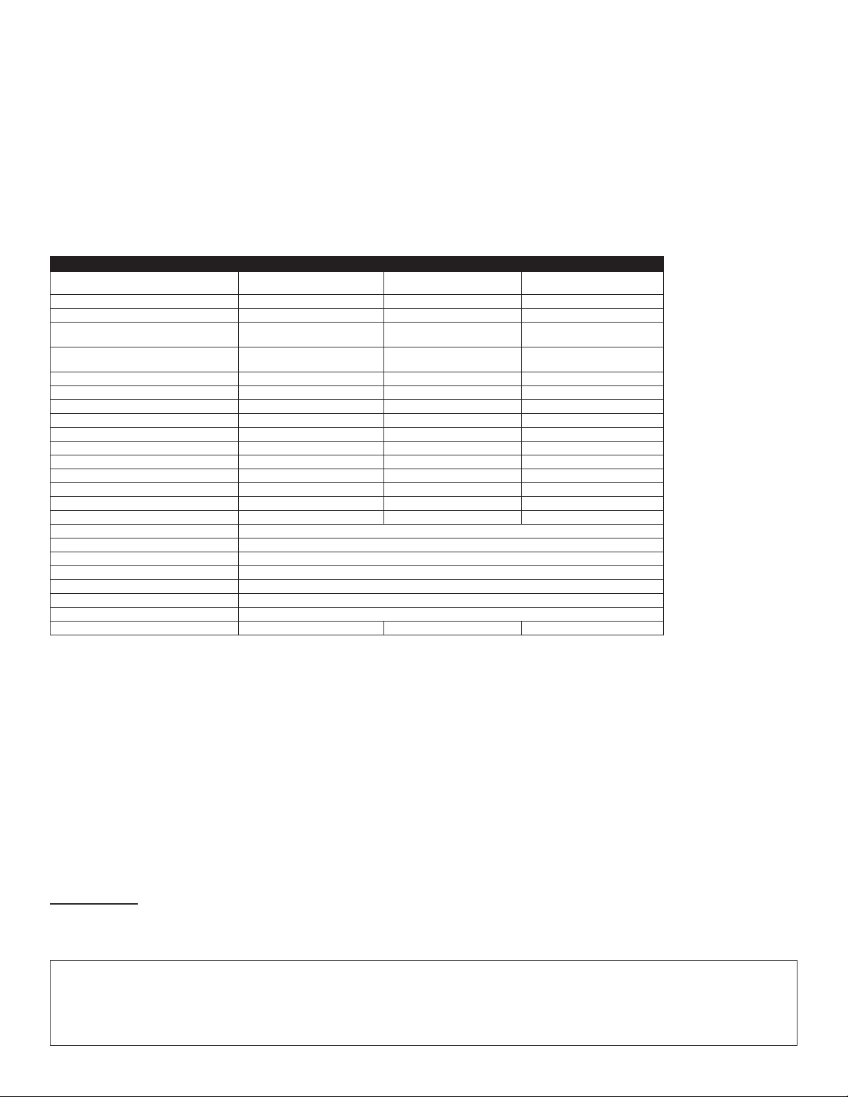
SPECIFICATIONS
Catalog Nos. LU20S-DNW
Switching Relay
LU107-DNW
0-10V Dimmer, 50 mA Sink
LU04P-1NW
Phase Cut Dimmer
Input Voltage/Frequency 120-277VAC, 50/60Hz 120-277VAC, 50/60Hz 120VAC, 60Hz
Input Current
120V Standby: 0.2W
Max: 0.5W+Load Current
Standby: 0.2W
Max: 0.5W+Load Current
Standby: 1.0W
Max: 1.2W+Load Current
277V Standby: 0.3W
Max: 0.6W+Load Current
Standby: 0.3W
Max: 0.6W+Load Current Not rated for use
Load Ratings
General Purpose Rating @ 120V 20A Not rated for use Not rated for use
LED, CFL, Electronic Ballast @ 120V 10A 8A 360W
LED, CFL, Electronic Ballast @ 277V 10A 5A Not rated for use
Mark 10®@ 120V Not rated for use Not rated for use 800VA
Magnetic Ballast @ 120V 10A 10A 800W
Magnetic Ballast @ 277V 10A 10A Not rated for use
Resistive, Tungsten @ 120V 6.67A 6.67A 800W
Resistive, Tungsten @ 277V 6.67A 6.67A Not rated for use
Motor @ 120V 1/4Hp (FLA 5.8A) 1/4Hp (FLA 5.8A) Not rated for use
Motor @ 277V 1/3Hp (FLA 3.0A) 1/3Hp (FLA 3.0A) Not rated for use
IP Rating IP30
Network Connections IEEE 802.15.4, 2.4GHz, wireless, mesh network up to 75 ft range between device
Operating Temperature 0°C - 50°C (32°F - 122°F)
Storage Temperature -40°C to 85°C (-40°F - 185°F)
Purpose of Control Operating control
Action Control Type 1
Pollution Degree 2
Impulse Voltage 4000V 4000V 2500V
Conguration and Programming
1. System Conguration is performed using the Leviton Lumina®RF SA application,
downloadable from Google Play or the Apple Store, using any Bluetooth™
enabled Android™or iOS™device. Use the
application to:
a. Manually add/remove devices to or from the room.
b. Add additional keypads, load controllers, sensors, switches or dimmers to the
room.
c. Change Sensor Parameters like Sensitivity, Timeout, target light level, and
other settings.
d. Create user dened groups of xtures.
e. Dene Scenes (Meeting, Presentation, Lunch, Dinner, Test, etc.).
PK-A3314-10-00-2A-X3
For Technical Assistance Call: 1-800-824-3005 (U.S. Only) or 1-800-405-5320 (Canada Only) www.leviton.com
2.Factory Default: resets device to out of the box state.
a. For LU20S and LU107:
• Push button on device for more than 20 seconds (but less than 25). Locator
light will blink AMBER at 5 and 20 second intervals.NOTE: release button
after 20 second light ash.
• Release button.
• When complete, device will reboot then revert to auto join mode where it is
searching for a network to join. Locator light will blink GREEN slowly while
looking for an open network.
b. For LU04P:
• Press and hold button for 14 seconds. The locator light quickly ash red/
amber.
• Release button.
• When reset is complete, device will reboot. Follow the LU04P instructions in
Installation section to add it into a system.
ARTWORK PRINT SPECIFICATIONS
DIMENSIONS / FOLD SCHEME / BINDERY DIAGRAM
PART NUMBER REV DESCRIPTION
Line Screen:
Angle:
Resolution:
Offset Flexo
Other
Body Material:
Bindery
Thickness:
Trim
Perfect Bind
Die cut Saddle Stitch
Drill
Fold
The information in this document is the exclusive PROPRIETARY property of LEVITON MANUFACTURING COMPANY, INC. It is disclosed
with the understanding that acceptance or review by the recipient constitutes an undertaking by the recipient. (1) to hold this information in strict
confidence, and (2) not to disclose, duplicate, copy, modify or use the information for any purpose other than that for which disclosed.
PlantApprovals:
PN-ARN: Pilot Rev:ECR Number:
Released Artwork Format: Production PDF Artwork Release Date:
Artwork Print Specification Sheet Rev A12.eps
PMCQA
Artist:
Notes:
Other
Cust Other
S & A
Mktg Eng
FOR LEVITON USE ONLY
SPECIFICATIONS :
PROCESS :
MANUAL INTERIORS / BINDERY / FOLD SCHEME :
COMMENTS :
For manuals - designates cover specifications
Material:
Thickness:
Finish:
:
Artwork must be printed at 100% (1:1 scale)
Spot
CMYK
1:
4:
3:
2:
Color(s): over
1:
4:
3:
2:
Fonts:
Spot
CMYK
1:
4:
3:
2:
Color(s): over
1:
4:
3:
2:
Fonts:
Fold Line
Die Cut Punch/Drill Hole
Glue
Kiss Cut Cellophane
Fold Line
Perforate
Die Cut
Die Line Key:
PK-A3314-10-00-2A-X3
40 lb.
Black
1 1
x
Helvetica
Instruction Sheet
x
x
x x
x
x
x
x
L. Walsh
EM0301-6268
A. Rogowicz
cc: R. Parks, L. Pukhrambam
M. Blonder V. LoNigro
R. Brown D. Moskovkin
cc: F. Tse
J. Tang
cc: H. Cai
08
8.5"
11"
Part No. 2.125"
2.75" Part No.
X3

This manual suits for next models

2

Other Leviton Control System manuals

Leviton DMX-512 User manual

Leviton

Leviton DMX-512 User manual

Leviton D4200 User manual

Leviton

Leviton D4200 User manual

Leviton DOS05 User manual

Leviton

Leviton DOS05 User manual

Leviton 600 Series User manual

Leviton

Leviton 600 Series User manual

Leviton DOS05 User manual

Leviton

Leviton DOS05 User manual

Leviton Decora DZR15 User manual

Leviton

Leviton Decora DZR15 User manual

Leviton 4106 User manual

Leviton

Leviton 4106 User manual

Leviton 48211-AVC User manual

Leviton

Leviton 48211-AVC User manual

Leviton Dimensions D3200 User guide

Leviton

Leviton Dimensions D3200 User guide

Popular Control System manuals by other brands

JETI model DUPLEX REX3 user manual

JETI model

JETI model DUPLEX REX3 user manual

Rockwell Automation Allen-Bradley CENTERLINE 2100 installation instructions

Rockwell Automation

Rockwell Automation Allen-Bradley CENTERLINE 2100 installation instructions

HBX SNO-0500 installation manual

HBX

HBX SNO-0500 installation manual

HEIDENHAIN iTNC 530 HSCI Technical manual

HEIDENHAIN

HEIDENHAIN iTNC 530 HSCI Technical manual

SICE Tech WHY PRO WHY-PH1 INSTRUCTION MANUAL AND WARNINGS

SICE Tech

SICE Tech WHY PRO WHY-PH1 INSTRUCTION MANUAL AND WARNINGS

CAME PS ONE SERIES installation manual

CAME

CAME PS ONE SERIES installation manual

Parklio Brain user manual

Parklio

Parklio Brain user manual

Norac UC7 installation manual

Norac

Norac UC7 installation manual

CiA KB manual

CiA

CiA KB manual

RTS OMNEO Main Station Technical manual

RTS

RTS OMNEO Main Station Technical manual

Rescue 42 PodRunner Command-Runner owner's manual

Rescue 42

Rescue 42 PodRunner Command-Runner owner's manual

Carefree BT12 user guide

Carefree

Carefree BT12 user guide

Kenwood KRF-V6200D Service manual

Kenwood

Kenwood KRF-V6200D Service manual

Exhausto EXact2 HMI2-350-TOUCH Basic instructions

Exhausto

Exhausto EXact2 HMI2-350-TOUCH Basic instructions

nvent RAYCHEM ACS-30 Programming guide

nvent

nvent RAYCHEM ACS-30 Programming guide

heat-timer SQ-Elite-8S Installation and operation instruction manual

heat-timer

heat-timer SQ-Elite-8S Installation and operation instruction manual

ENTRYPASS EP.MINI Wiring guide

ENTRYPASS

ENTRYPASS EP.MINI Wiring guide

Jandy AquaLink RS6 troubleshooting manual

Jandy

Jandy AquaLink RS6 troubleshooting manual

manuals.online logo
manuals.online logoBrands
  • About & Mission
  • Contact us
  • Privacy Policy
  • Terms and Conditions

Copyright 2025 Manuals.Online. All Rights Reserved.