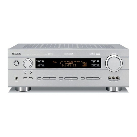
STUDER REVOX B780 User manual

STUDtrR Rd/OX
8780. 18739
MONTAGE-ANTEITUNG FUR DIE NETZFERNEINSCHATTUNG
INSTATTATION INSTRUCTIONS FOR REMOTE
POWER-ON KIT
INSTRUCTION DE MONTAGE POUR gENCTENCHEMENT
A DISTANCE
t .Lat^:..f,'
Printed in Swirzerland by WILLI STUDEF 18654.181
Copyright by Wl LLI STUDER, CH-8105 Regensdorf-Zürich, Switzerland

Die l\ilontage sol I te aussch I iessl i ch durch R EVO X-
Servicestel len ausgeführt werden.
Stückliste
Der Bausatz enthält folgende Bauteile:
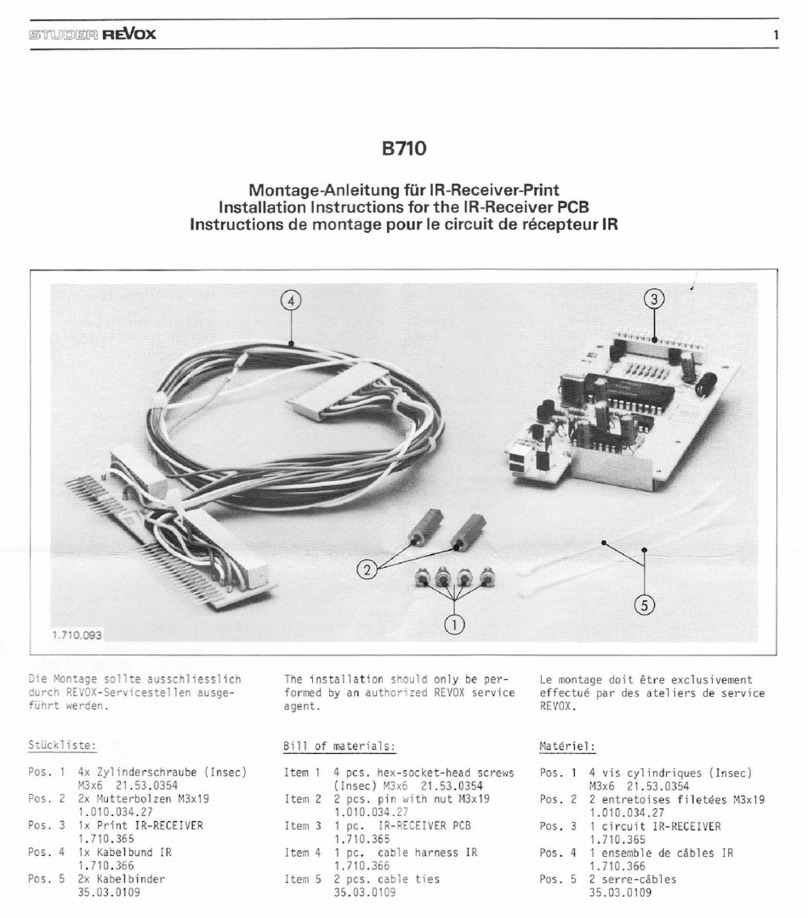
Pos. 1 2x Kreuzschlitz-Schraube M3x10
21 .26.0356
Pos.2 2 x Kreuzschlitz-Schraube M3x6
21 .26.0354
Pos.3 2x Mutterbolzen M3x30
1.780.440-01
Pos. 4 1 x Print POWER-ON REMOTE CON-
TROL
1.180.430
Pos.5 1 x Kabelbund REIVOTECONTROL
1.780.435
1 x Verbindunqskabel 3710-139/lB0
Werkzeuge
Es werden folgende Werkzeuge benötigt:
je 1 Kreuzschlitz-Schraubenzieher, Grösse 1, 2
1 Pinzette
Vorbereitung
Am Gerät Netzstecker ziehen, Akkus für Stations-
speicherung entfernen (Frequenzen und Speicher-
plätze werden dabei gelöscht).
Installation of this kit should be carried out by
a FEVOX service dealer.
Parts list
The kit consists of the followlng parts:
Pos. 1
Pos. 2
Pos. 3
Pos. 4
2 x cross slotted screw M3x10
21 .26.0356
2 x cross slotted screw M3x6
21.26.0354
2 x threaded stud lv3x30
1.180.440-01
1 x PC board POWER-ON REIVOTE
CONTRO L
1.780.430
Pos. 5 1 x wrre harness RENiIOTE CONTROL
1.780.435
1 x interconnecting cable 8710-7391180
Tools
The following tools are required for installation:
- .1 cross slot (Phillips) screwdriver size 1
- 1 cross slot (Phillips) screwdriver size 2
- 1 pair of tweezers
heparations
Disconnect the equipment from the electrical
current supply and remove the storage batteries
from the battery compartment. (This results in
the cancellation of all frequencies and memory
positions in the memory unit.)
1 l;l il i,;1 ;: iil r 9e !: 3f
SiW::::
Ce montage ne peut ötre effectuÖ que par un ser-
vice REVOX.
Liste de pidces
Le jeu de montaqe comprend les 6l6ments sui-
vants:
Pos. '1 2 x vis ä croix M3x'l 0
21 .26.0356
Pos.22x visäcroixM3x6
21 .26.0354
Pos. 3 2 x entretoises filetdes M3x30
1.184.440-01
Pos.4 '1 x plaquerre POWER-ON RENlOTE
CONTROL
1.780.430
Pos. 5 1 x tasse de cäbles R EMOTE CONTRO L
't .780.435
'l x cäble de liaison 8110-7391180
Outillage
Les ouLils su'vants sonl nÖcessaires:
- tournevis ä croix, grandeurs 1 er2
- 1 pincette
P16paration
Retirez la fiche secteur de l'appareil et d6posez
les accumulateurs (ce qui provoque l'effacemenl
des fr6quences et des places de stations m6mori-
s6es).
d
,#
,s
ds
,s
AT
e"*
'E. tr\,
.,$k*er_
r:r:'i;; i i il

Dismantling Dömontage
Fusslejste IA]entfernen (2 Schrauben IB] )
Bodenblech abschrauben (5 Schrauben ICl )
Oberes Deckblech ID] ausbauen:
2 Schrauben I E] entfernen
Remove toe raillAl (undo 2 crews at {Bl)
Femove bottom plate (5 screws at IC])
Remove top cover ID]
Undo 2 screws at IE]
Enlevez le pred {,AJ (2 vis IB])
D6vissez la töle du fond (5 vis IC])
Enlevez la plaque de Tecouvrement sup6rieure ID]
Enlevez 2 vis IE]
T---;-----l CONNECTION CABLE
POWER-ON
ART. NO. 33210 8739/780 |
[I-^;*rö€r. -l
, 8780: 1.780.140 ,.
['-'-'- .l 8739: 3
'I POWER
ON
l_ roryg n-o-rv_55yo.r "o^."o. i
DIN SOCKET DIN SOCKET
4 POLE 5 POLE I
-+ä-:/-Yl
+ Kl L-<t__f1
,-il
I POWER-ON SCOPE, i \-_^J
tAA.i m
r __ __r'^Qr: '"Qt:L_ _'_r
Prinzipschema Basic circuit diagram Sch6ma de principe q+

Einbau des Relaisprint
1.780.430
2 Befestigungsschrauben IF] des POWER DIS-
TR I BUTI ON PCB entfernen und durch 2 Schrau-
ben Pos. 1 erse?en.
Die beiden l\,4utterbolzen Pos. 3 von oben auf die
vorstehenden Schrauben Pos. .1 aufschrauben und
Stecker IG] ausziehen.
Den vierpoligen Stecker des Kabelbund Pos. 5 an
Stelle des Steckers IG] des POWEF DISTRiBU-
TION PCB einstecken.
lnstallation of Remote Control Board
1.780.430
Remove the 2 mounting screws IF] of the POWER
DISTBIBUTION board and replace them with
the screws of Pos. 1.
Attach the two threaded studs Pos. 3 to the ex-
posed ends of the screws Pos. 1. Pull out plug [G].
Insert the 4-pin connector of the wire harness
Pos. 5 in place of the plug [G] on the POWER
DISTRIBUTION board.
Montage de la plaquette POWER-ON RC
1.780.430
Enlevez les 2 vis de f ixation IF] du POWER DIS-
TR IBUTION PCB et remplacez-les par 2 vis Pos.
1.
Vissez dans Ia partie sup6rieure les deux entre-
toises filetöes Pos. 3 sur les deux vis (Pos. '1 ) pr6-
cödemment viss6e et relirez la fiche [G].
Ansicht von oben / View f rom top
Vue de dessus
Fixez la plaquette POWFR-ON BC Pos. 4 sur les
entretoises filet6es Pos. 3 ä l'aide des vis Pos. 2.
Vu de l'arriöre, le relais doitötre se pr6senter ä
gauche. p66661'dez la fiche IG] ä la plaquette
POWER-ON RC, ainsi que la fiche IH] ä 6 pöles
de la tresse de cäbles Pos- 5. Placez les 2 cäbles
ill (gris/blanc) en dessous ä droite.
Les deux cäbles [ | ] sont ä ins6rer dans I K]. Cette
fiche doit ötre retir6e.
739: Fiche droite le cäble qris ä la place 3 (ä
partir de la droite)
le cäble blanc ä la place 5
780. cäble gris ä la place 1 (ä partir de la
droire)
cäble blanc ä la place 5
Remontage
Fixez ä nouveau la töle du fond, les pieds et la
plaque de recouvrement. Replacez les accumula-
teurs; la mdmoire des stations doit ötre repro-
grammde.
Ansicht von unten / Bottom view
Vue de dessous
Ansicht von unten / Bottom view
Vue de dessous
Relaisprint Pos. 4 mit den Schrauben Pos. 2 auf
den l\lutterbolzen Pos. 3 befestigen. Das Felais
muss sich, von hinten gesehen, links befinden.
Stecker IG] auf Relaisprint einstecken. Kabel-
bund Pos. 5: sechspoligen Stecker IH] auf Re-
laisprint einstecken. Die beiden Kabel I l (grlws)
nach rechts unten schieben.
Die beiden Kabe Il werden in den Stecker IK]
eingesetzt. Dieser Stecker muss dazu auSgezogen
werden.
739' Rechter Stecker graues Kabel an Platz 3
(von rechts)
weisses Kabel an Platz 5
780: graues Kabel an Platz 'i {von rechts)
weisses Kabel an Platz 5
Zusammenbau
Deckblech, Bodenblech und Fussleiste wieder be-
festigen. Akkumulatoren einbauen; der Emp-
fangsspeicher muss neu programmiert werden.
Ansicht von oben / View f rom top
Vue de dessus
Ansicht von unten / Bottom view
Vue de dessous
Attach the board Pos. 4 to the threaded studs
Pos. 3 with the l\l3x6 screws of Pos. 2. lf viewed
from the back, the relay must be on the left-
hand side. Insert plug IG]and the 6-pin plug IH]
of the wire harness into the board. Push the two
cables I I ] (grylwht) towards the right and down.
Insert both cables I l into the plug I K]. To insert
the cables, the plug must be removed from its
mat.nq conneclor.
739: Right-hand plug grey cable to pin 3
(from the right)
white cable to pin 5
780: grey cable to pin 1 (from the right)
white cable to pin 5
Reassembly
lnstall top cover, bottom plate and toe rail. ln-
sert storage batteries into the battery compart-
ment. The station memory has to be programmed
again.
This manual suits for next models
1
Other STUDER REVOX Receiver manuals
