Studer MBC 12-08 User manual

MBC Battery chargers, switch-mode, 3-STEP, IP65
Type MBC 12-06/1 MBC 12-15/1 MBC 24-03/1 MBC 24-08/1
Battery voltage (Vdc) 12 12 24 24
Input voltage (Vac) 100-260 100-260 100-260 100-260
Charge voltage (boost) 14.4 14.4 28.8 28.8
Charge voltage (float) 13.8 13.8 27.6 27.6
Output (Amp.) 6 15 3 8
Cooling Heat sink Heat sink Heat sink Heat sink
Outputs 1 1 1 1
Frequency 40-60 Hz 40-60 Hz 40-60 Hz 40-60 Hz
Efficiency > 85 % > 85 % > 85 % > 85 %
Ambient temp. range -25 to 50°C -25 to 50°C -25 to 50°C -25 to 50°C
Dimensions lxwxh (mm) 155x80x36 195x100x47 155x80x36 195x100x46
Weight (kg) 0.9 1.8 0.9 1.8
Recommanded battery capacity 18-60 Ah 45-150 Ah 9-30 Ah 24-80 Ah
Switch over current (A) 0.17-0.23 0.68-0.92 0.17-0.23 0.34-0.46
Secondary fuse (A) 7.5 20 7.5 15
Input wired (Vac) ✔✔✔✔
Output wired (Vdc) ✔✔✔✔
Warranty 2 years
MBC 12-15/1
MBC Battery chargers, switch-mode, 3-STEP
Type MBC 12-08/2 MBC 12-12/2 MBC 12-25/3 MBC 12-30/3 MBC 12-40/3 MBC 12-60/3
Battery voltage (Vdc) 12 12 12 12 12 12
Input voltage (Vac) 115-230 115-230 115-230 83-280 83-280 83-280
Charge absorption volt. (Vdc) 14.1 (14.4*) 14.1 (14.4*) 14.1 (14.4*) 14.1 (14.4*) 14.1 (14.4*) 14.1 (14.4*)
Charge float voltage (Vdc) 13.5 (13.8*) 13.5 (13.8*) 13.5 (13.8*) 13.5 (13.8*) 13.5 (13.8*) 13.5 (13.8*)
Output (Amp.) 8 12 25 30 40 60
Cooling Natural Fan Fan Fan Fan Fan
Outputs 2 2 3 3 3 3
Frequency 45-66 Hz 45-66 Hz 45-66 Hz 45-66 Hz 45-66 Hz 45-66 Hz
PFC
✔✔✔
Ambient temp. range -20 to +70°C -20 to +70°C -20 to +70°C -20 to +70°C -20 to +70°C -20 to +70°C
Dimensions lxwxh (mm) 155x205x75 155x205x75 155x268x75 272x334x127 272x334x127 272x412x127
Weight (kg) 1.3 1.4 2.3 4.2 4.2 5.4
EMC class EN 55022/B
Warranty 2 years
* GEL batteries MBC12-25/3
Type MBC 12-80/3 MBC 24-12/2 MBC 24-30/3 MBC 24-60/3 MBC 24-80/3
Battery voltage (Vdc) 12 24 24 24 24
Input voltage (Vac) 83-280 115-230 83-280 150-280 150-280
Charge voltage (boost) (Vdc) * 14.1 (14.4*) 28.2 (28.8*) 28.2 (28.8*) 28.2 (28.8*) 28.2 (28.8*)
Charge voltage (float) (Vdc) * 13.5 (13.8*) 27.0 (27.6*) 27.0 (27.6*) 27.0 (27.6*) 27.0 (27.6*)
Output (Amp.) 80 12 30 60 80
Cooling Fan Fan Fan Fan Fan
Outputs 3 2 3 3 3
Frequency 45-66 Hz 45-66 Hz 45-66 Hz 45-66 Hz 45-66 Hz
PFC ✔✔✔✔
Ambient temp. range -20 to +70°C -20 to +70°C -20 to +70°C -20 to +70°C -20 to +70°C
Dimensions lxwxh (mm) 272x495x127 155x268x75 272x412x127 272x495x127 272x495x127
Weight (kg) 7.1 2.3 5.4 7.1 7.1
EMC class EN 55022/B
Warranty 2 years
* GEL batteries
MBC 12-60/3
548/mbc
STUDER Innotec
Rue des Casernes 57
Tel. : + 41 (0) 27 205 60 80 info@studer-innotec.com
CH – 1950 Sion Fax : + 41 (0) 27 205 60 88 www.studer-innotec.com

Pag. 1 MBC 12-08/2, 12-12/2, 12-25/3, 24-12/2
INDEX
Pag. 13 MBC 12-30/3, 12-40/3, 12-60/3, 24-30/3
Pag. 29 MBC 12-80/3, 24-60/3, 24-80/3

REV 000
User’s Manual
MBC BATTERY CHARGER
MBC BATTERY CHARGER
MBC 12-08/2
MBC 12-12/2
MBC 12-25/3
MBC 24-12/2
GB
1

2
Pag. 3-4 Characteristics and Installation
Pag. 5Installation: voltage supply, batteries
Pag. 6Installation: Selecting the charging
method
Pag. 7Operation: Control signal,
Pag. 8Ope characteristicsration: Charging
Pag. 9Operation: Control panel - Maintenance
Pag. 10Technical data
INDEX
GB

CHARACTERISTICS AND INSTALLATION
GB
3
MBC BATTERY CHARGER SERIES BATTERY CHARGER
The long experience we have in the nautical field has given us the ability to evolve the range of MBC
battery chargers, now called MBC BATTERY CHARGER, with superior performance to those currently on the
market. The high level of performance of the MBC BATTERY CHARGER gives a charge to the batteries which
is both fast and safe.
Other important advantages which the MBC BATTERY CHARGER battery chargers offer, are:
• Three stage IUoU battery charging.
• Multiple outputs in order to charge more groups of batteries (internal battery isolator diodes).
• Charge selector for liquid/gel electrolyte batteries.
• Low residual fluctuation on output (ripple lower than 30 mV RMS).
• Compatible with every kind of generator.
• Short circuit, overloading, output overvoltage and overheating protection.
• Can work in a wide range of ambient temperatures.
INSTALLATION
BEFORE USING THE BATTERY CHARGER CAREFULLY READ THIS USER’S MANUAL. IN CASE OF
DOUBT CONTACT THE “STUDER INNOTEC” SUPPLIER OR AFTER SALES SERVICE DEPARTMENT.
THE BATTERY CHARGERS HAS BEEN DESIGNED FOR FIXED INSTALLATIONS (FOR INDOOR USE
ONLY).
“Studer Innotec” battery chargers have been designed and made for the reasons described in this
user’s manual. The “Studer Innotec” Company does not accept any responsibility for direct or
indirect damage caused by improper use of the equipment, bad installation or by possible errors
occurring in this manual.
THE OPENING OF THE BATTERY CHARGER BY UNAUTHORISED PERSONNEL MAKES THE
WARRANTY VOID.
THE PACKAGE CONTAINS: battery charger - warranty card - user’s manual - cable terminals (to be
used for connection to the output terminals).

CHARACTERISTICS AND INSTALLATION
GB
4
INSTALLATION SITE
Install the battery charger in a dry and ventilated place and as near to the batteries as possible. The
battery charger, although having high efficiency, develops a certain amount of heat during function-
ing, therefore, it is imperative that the installation area has sufficient ventilation, enough to allow use
of the equipment at maximum power.
The battery charger can be installed in a horizontal or vertical position with cables coming out in the
downward position. The vertical position is recommended because the natural convection of heat
helps to cool the equipment. The perimeter of the battery charger (except the base) must be kept at
a distance from walls or objects by a minimum of 5 cm.
FIG.1
The cables connected to the output terminals have a maximum length of 4 metres.
WARNING: the battery charger must be used only with a re-chargeable lead/liquid
electrolytic batteries or lead/gel (sealed or non-sealed).
WARNING: the outer surface of the battery charger is used as a heat sink, therefore it may
reach very high temperatures (risk of burns). Leave the equipment to cool down before
handling it.
MODEL
Battery voltage
Battery capacity
Minimum output cable size
MBC 12-08/2 MBC 12-12/2 MBC 12-25/3 MBC 24-12/2
12 V 24 V
35 ÷ 80 Ah 55 ÷ 120 Ah 110 ÷ 250 Ah 55 ÷ 120 Ah
4 mm
2
6 mm
2
10 mm
2
6 mm
2
EQUIPMENT REQUIRED FOR INSTALLATION
On the basis of the type of model, use the batteries and cables on the output terminals as specified
in the following table:

5
INSTALLATION
GB
BATTERY
WARNING: during charge, batteries can generate explosive gases, therefore avoid sparks or
naked flames. Provide adequate ventilation to the battery area whilst charging.
WARNING: before connecting the batteries check the terminals of the cables from the bat-
tery. Reversing the terminals could seriously damage the battery charger even if protected by
fuses.
The positive terminal of the battery or of the group of batteries must be connected to one of the posi-
tive terminals of the battery charger. The negative terminal of the battery or of the group of batteries
must be connected to the negative terminal of the battery charger. To make the connections use the
cable terminals supplied with the equipment.
EQUIPMENT SUPPLY
The equipment already includes a power cable for AC supply. For connections to an AC supply see
fig.2. Before powering up the battery charger check that the power supply voltage, described on the
rating label, corresponds to that supplied by the AC supply source.
In the electrical circuit a two-pole switch must be installed for the sole use of switching the equip-
ment ON & OFF.
The insulation between the contact points of the connections of the AC supply must be at least 3 mm.
The connections to the AC supply must be carried out according to local electrical codes.
WARNING: before connecting or disconnecting the cables from the electrical terminals of the bat-
tery charger, make sure that the equipment is disconnected from the AC mains and the batteries.
WARNING: in cases where the power cable could be damaged, have this changed by a “Studer
Innotec” service centre. In order to avoid accidents, the equipment must only be opened by au-
thorised personnel.
5 cm
5 cm
5 cm 5 cm
FIG.2
battery
n° 2
battery
n° 1
Battery
switches
Blue
Yellow
Green
Brown
Neutral
Earth
Live
SLAVE A MASTER

6
INSTALLATION
GB
SELECTION OF THE CHARGING MODE
The battery charger can be set to optimize the charge according to the type of battery used, either
liquid or gel electrolytic. The selection of the type of charge is made via the switch placed in the ter-
minal board area, as indicated in Fig.3a.
When charging liquid electrolytic, re-arrange the switch to position EL, for batteries with gel elec-
trolytic to the position GEL.
A
V
V
V
2
1
8
9
3
4
5
6
7
5
4
9
-
Vbat
1
27
38
6
MASTER
Slave A
Slave B
FIG.3 b
WARNING: check the charge mode. Incorrect selection
could cause shorter battery life or lengthen the char-
ging time.
FIG.3 a
If the installation has only one or two groups of batteries, always connect the output marked “MAS-
TER”. This is the main outlet of the battery charger.
If the “MASTER” is not connected, the battery charger may supply an output voltage lower than rated.
It is advisable to connect the group of batteries which are used more often (typically the service
group) to the MASTER output terminal.
The positive output terminals which are not used must be kept free (do not bridge the terminals).
WARNING: the use of inadequate size cables and incorrect connection of the terminals or
electrical joints may result in dangerous overheating of the connecting terminals or cables.
BATTERIES
WITH GEL
ELECTROLYTE
BATTERIES
WITH
LIQUID
ELECTROLYTE
TOTAL CURRENT
BASIC STATE
FIG.3.1 FIG.3.2

7
OPERATING
GB
CONTROL SIGNALS (ONLY MBC 12-25/3)
The battery charger has a 9-pin female connector (connector DB9, see fig..4) on which the analog si-
gnals can be seen and used to monitor and control the equipment.
The position and description of the signals on the connector are listed below:
BASIC STATE OF BATTERY CHARGER
Description
Positive MASTER output (650mA max). By drawing 100mA the error is less than 0.7%.
Positive SLAVE A output (650mA max). By drawing 100mA the error is less than 0.7%.
Not connected or if it present, positive SLAVE B output (650mA max). By drawing 100mA the error is less
than 0.7%.
Basic state of battery charger (20 mA max).
Battery charger total current positive shunt (10 mA max). The transduction ratio is 100mV/100A.
GND signal 1 (V master).
GND signal 2 (V slave A).
GND signal 3 (V slave B, if it present).
Battery charger total current negative shunt.
Connection PIN 4
HIGH IMPEDENCE
+ V CHARGE
State
OFF or PROBLEMS
ON WITHOUT PROBLEMS
For a wiring example of control signals look at figure 3b.
Number
1
2
3
4
5
6
7
8
9
The position and description of the signals on the connector are listed below.
CHARGE
POWER
FLOAT
CHARGE
POWER
FLOAT
12345
6789
CONTROL PANEL LED SIGNAL CONTROL
CONNECTOR
FIG. 4
SLAVE A MASTER
8
OPERATING
GB
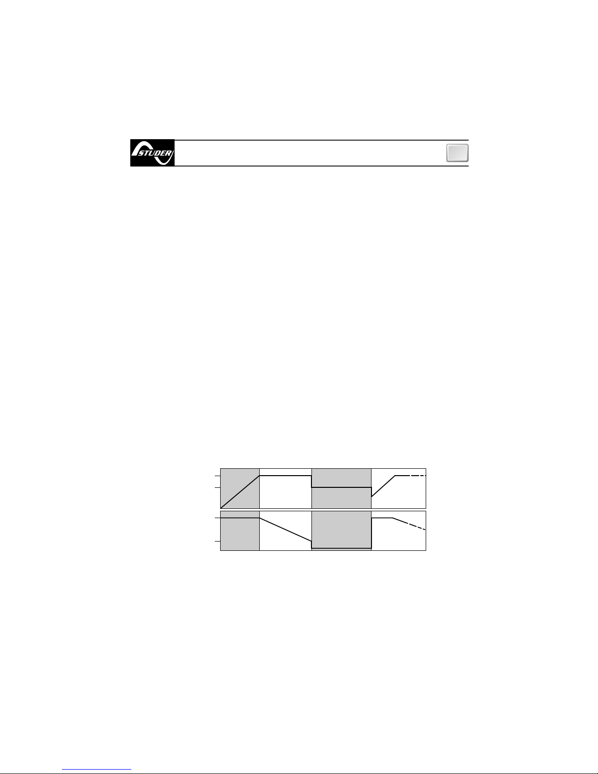
BULK phase (constant current) - The batteries need more current than the battery charger can sup-
ply. Current is limited to the maximum rated output. The battery charger can enter this phase during
start-up, when the batteries are low or when a high load is connected.
ABSORPTION phase (constant voltage) - The battery charger charges the batteries at a constant
ABSORPTION voltage and at the current they need.
The current needed by the batteries will tend to diminish over time. When the required current is less
than 20% of the maximum output value, the charger will change to the FLOAT phase.
FLOAT phase (maintenance) - The battery charger charges the batteries at the constant FLOAT volt-
age. In this phase, as the batteries reach maximum capacity, they will tend to absorb current close to
zero Ampere. This FLOAT phase will allow the batteries to be on charge without the risk of overload-
ing. The next step to the ABSORPTION phase occurs when the demand for current goes over 20% of
the maximum output value.
CHARGING CHARACTERISTICS
Charging occurs in 3 phases:
OPERATION
When the battery charger is switched on, it automatically selects the optimum charge mode to
best suit the batteries or load connected. The battery charger has a loading characteristic of the
IUoU type.
(V)
14.1 (28.2) [Gel 14.4 (28.8)]
(I)
Imax
20% Imax
BULK ABSORPTION FLOAT NEW CYCLE
TIME
TIME
13.5 (27.0) [Gel 13.8 (27.6)]

9
OPERATING - MAINTENANCE
GB
MAINTENANCE
The battery charger does not need any maintenance. To ensure optimum performance from the
equipment, once a year check the cables and the electrical connections.
CONTROL PANEL
The control panel is made-up of three LEDS:
POWER LED, FLOAT LED and CHARGE LED (BULK, ABSORPTION, see fig.4)
The information supplied by the LEDS are listed below:
POWER LED
FLOAT LED
LED Color
No indication
FLOAT phase - FLOAT charge
Short circuit or overload in output.
Check output cables, the group of batteries and the points of use connected to the battery charger.
LED Status
Description
LED Color
Off No mains power or overheating.
In case of overheating check if the installation of the battery charger is correct.
Switch off and allow the equipment to cool down for at least 10 minutes.
Power ON
Green
Description
Off
Green
Green
Off
Fixed
Flashing
CHARGE LED (BULK, ABSORPTION)
LED Color
No indication
ABSORPTION phase or BULK phase
Short circuit or overload in output.
Check output cables, the group of batteries and the points of use connected to the battery charger.
LED Status
Description
Off
Yellow
Yellow
Off
Fixed
Flashing
10
TECHNICAL DATA
GB
STUDER RESERVES THE RIGHT TO MODIFY THE TECHNICAL CHARACTERISTICS OF THE EQUIPMENT AND THE CONTENTS OF THIS MANUAL WITHOUT PRIOR NOTICE.
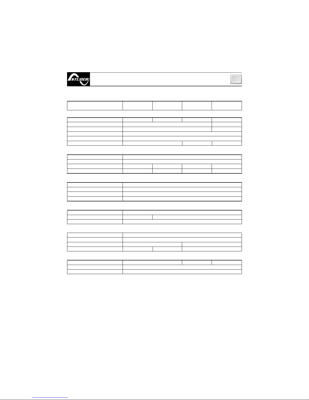
MODEL MBC12-08/2 MBC12-12/2 MBC12-25/3 MBC24-12/2
MBC12-08/2 DR MBC12-12/2 DR MBC12-25/3 DR MBC24-12/2 DR
OUTPUT CHARACTERISTICS
Maximum output current(1)
Charge absorption voltage
Charge float voltage
Residual ripple (2)
Charging characteristics
Number of outputs (3)
8 A 12 A 25 A 12 A
14,1 Vdc (14,4 Vdc GEL) 28,2 Vdc (28,8 Vdc GEL)
13,5 Vdc (13,8 Vdc GEL) 27,0 Vdc (27,6 Vdc GEL)
30mV RMS max
Automatic in three stages IUoU
232
Yes, through fuse
Yes
Yes
Yes
207÷260 Vac (207÷260 Vac or 103÷130Vac
(5) (
*
)
)
45÷66 Hz
1,2 A 1,8 A 3,2 A 3,0 A
2,4 A 3,6 A 6,4 A 6,0 A
-20 to +70 °C, with power reduction over +50 °C
Natural Forced, with controlled fan (2 speed)
Max.95% RV without condensation
No Yes No
EN 60335-2-29
EN 55022/B
Aluminium - Cycoloy ®
Anodized - OR5066
155 x 205 x 75 mm 155 x 268 x 75 mm
1,3 Kg 1,4 Kg 2,3 Kg
INPUT CHARACTERISTICS
PROTECTION
Supply voltage (4)
Frequency
Maximum absorption (230 Vac) (6)
Maximum absorption (115 Vac) (6) (*)
CASE
Material
Colour
Dimensions (WxHxD)
Weight
Reverse polarity (7)
Overload
Output short circuit
Overheating
AMBIENT CHARACTERISTICS
Operating temperature
Cooling
Humidity
GENERAL
Connector for remote panel
Safety classification
EMC class
(*)
available early 2005
(1)
Maximum value at normal use or in short circuit.
(2)
At maximum output current on resistive load.
(3)
Each output can supply the maximum value of nominal current. The sum of the currents supplied from each output can not exceed
the maximum nominal value of the equipment.
(4)
Without power derating.
(5)
The battery charger measure the input AC voltage and choose the correct working input range.
(6)
With supply voltage specified as and output current equal to the maximum nominal value.
(7)
The protection could be inefficient in some operative conditions.
Cycoloy ® is a registered trade mark of GE Plastics.
TECHNICAL DATA
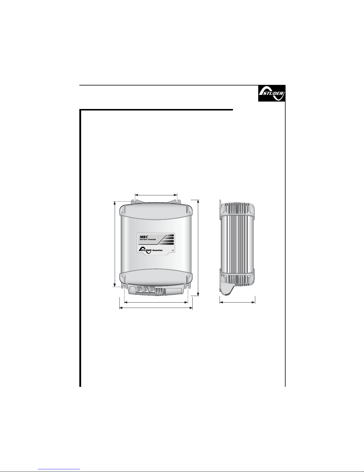
205
181
90
135
155
75
MBC BATTERY CHARGER -
DIMENSIONS (mm)
12-08/2
12-12/2
11

12
268
244
90
135
155
75
MBC BATTERY CHARGER -
DIMENSIONS (mm)
12-25/3
24-12/2

REV 001
MBC BATTERY CHARGER
MBC 12-30/3
MBC 12-40/3
MBC 12-60/3
MBC 24-30/3
User’s Manual
MBC BATTERY CHARGER
GB
13

14
Pag. 15Characteristics and Installation
Pag. 17Installation: voltage supply, batteries
Pag. 18Installation: Selecting the charging
method
Pag. 19 Operation: Control signal,
Pag. 20Operation: Charging characteristics
Pag. 21Operation: Control panel
Pag. 22-23Notification signs
Pag. 24-25Programming the battery charger
Pag. 26Maintenance - Technical data
INDEX
GB

CHARACTERISTICS AND INSTALLATION
GB
MBC BATTERY CHARGER SERIES BATTERY CHARGER
The long experience we have in the nautical field has given us the ability to evolve the range of
MBC battery chargers, now called MBC BATTERY CHARGER, with superior performance to
those currently on the market. The high level of performance of the MBC BATTERY CHARGER
gives a charge to the batteries which is both fast and safe.
Other important advantages which the MBC BATTERY CHARGER battery chargers offer, are:
• Three stage IUoU battery charging.
• Multiple outputs in order to charge more groups of batteries (internal battery isolator diodes).
• Differentiated charging for liquid electrolite or gel batteries.
• Integrated fuses inside the battery chargers (one for each output).
• Thermal battery protection (with optional sensors).
• Ability of providing full output power with low supply voltage.
• The possibility of using the battery charger as a power supply without batteries.
• Low residual fluctuation on output (ripple lower than 30 mV RMS).
• Universal AC supply input (280 ÷ 83 Vac, 45 ÷ 66 Hz).
• Power factor (cos ϕ) equal to 1.
• Compatible with every kind of generator.
• Short circuit, overloading, output overvoltage and overheating protection.
• Can work in a wide range of ambient temperatures.
• Variable speed for the cooling fan.
• High-technology control panel.
• Automatic and manual half power mode.
• CAN BUS interface for data transfer.
• Case constructed in stainless steel, Cycoloy®.
INSTALLATION
BEFORE USING THE BATTERY CHARGER CAREFULLY READ THIS USER’S MANUAL.
IN CASE OF DOUBT CONTACT THE “STUDER INNOTEC” SUPPLIER OR AFTER SALES
SERVICE DEPARTMENT.
THE BATTERY CHARGERS HAS BEEN DESIGNED FOR FIXED INSTALLATIONS (FOR INDOOR
USE ONLY).
“Studer Innotec” battery chargers have been designed and made for the reasons described in
this user’s manual. The “Studer Innotec” Company does not accept any responsibility for direct
or indirect damage caused by improper use of the equipment, bad installation or by possible
errors occurring in this manual.
THE OPENING OF THE BATTERY CHARGER BY UNAUTHORISED PERSONNEL MAKES THE
WARRANTY VOID.
THE PACKAGE CONTAINS: battery charger - warranty card - user’s manual - cable terminals
(to be used for connection to the output terminals).
15

INSTALLATION SITE
Install the battery charger in a dry and ventilated place and as near to the batteries as possi-
ble. The battery charger, although having high efficiency, develops a certain amount of heat
during functioning, therefore, it is imperative that the installation area has sufficient ventila-
tion, enough to allow use of the equipment at maximum power.
The battery charger can be installed in a horizontal or vertical position with cables coming
out in the downward position. The vertical position is recommended because the natural
convection of heat helps to cool the equipment. The perimeter of the battery charger (except
the base) must be kept at a distance from walls or objects by a minimum of 5 cm.
CHARACTERISTICS AND INSTALLATION
GB
The cables connected to the output terminals have a maximum length of 4 metres.
WARNING: the battery charger must be used only with a re-chargeable lead/liquid
electrolytic batteries or lead/gel (sealed or non-sealed).
16
FIG.1
PART. A
PART. B
EQUIPMENT NECESSARY FOR INSTALLATION
On the basis of the type of model, use the batteries and cables on the output terminals as
specified in the following table:
MODEL
Battery voltage
Battery capacity
Minimum output cable size
MBC 12-30/3 MBC 12-40/3 MBC 12-60/3 MBC 24-30/3
12 V 24 V
140 ÷ 300 Ah 180 ÷ 400 Ah 270 ÷ 600 Ah 140 ÷ 300 Ah
10 mm
2
16 mm
2
25 mm
2
10 mm
2

17
BATTERIES
To access the output terminals it is necessary to remove the cover by loosening the two screws
which hold it on top (see fig. 1 Part A). Before making the connections to the cables from the bat-
tery, loosen or remove the cable clamps by loosening the screws which fix it to the base (Fig.1
Part B).
WARNING: during charge, batteries can generate explosive gases, therefore avoid
sparks or naked flames. Provide adequate ventilation to the battery area whilst charg-
ing.
WARNING: before connecting the batteries check the terminals of the cables from the
battery. Reversing the terminals, could seriously damage the battery charger even if pro-
tected by fuses.
INSTALLATION
GB
EQUIPMENT SUPPLY
The equipment already includes a power cable for AC supply. For connections to an AC supply
see fig.2. Before powering up the battery charger check that the power supply voltage, de-
scribed on the rating label, corresponds to that supplied by the AC supply source.
In the electrical circuit a two-pole switch must be installed for the sole use of switching the
equipment ON & OFF. The insulation between the contact points of the connections of the AC
supply must be at least 3 mm. The connections to the AC supply must be carried out according
to local electrical codes.
WARNING: before connecting or disconnecting the cables from the electrical terminals of
the battery charger, make sure that the equipment is disconnected from the AC mains and
the batteries.
WARNING: in cases where the power supply cable could be damaged, have this
changed by a “Studer Innotec” service centre. In order to avoid accidents, the equip-
ment must only be opened by authorised personnel.
5 cm
5 cm
5 cm
5 cm
FIG.2
battery
n° 3
battery
n° 2
battery
n° 1
Battery switches
Blue
Yellow
Green
Brown
Neutral
Earth
Live
SLAVE B SLAVE A MASTER

18
INSTALLATION
GB
The positive terminal of the battery or of the group of batteries must be connected to one of the
positive terminals of the battery charger. The negative terminal of the battery or of the group of
batteries must be connected to the negative terminal of the battery charger. To make the con-
nections use the cable terminals supplied with the equipment.
If the installation has only one or two groups of batteries, always connect the output marked
“MASTER”. This is the main outlet of the battery charger.
If the “MASTER” is not connected, the battery charger may supply an output lower voltage than
rated and therefore less power.
It is advisable to connect the group of batteries which are used more often (typically the ser-
vice group) to the MASTER output terminal.
The positive output terminals that are not used must be kept free (do not bridge the terminals).
WARNING: the use of inadequate size cables and the incorrect connection of terminals
or electrical joints may result in dangerous overheating of the connecting terminals or
cables.
83
1
6
7
8
9
2
3
4
5
BASIC STATE
C
A
N
1
C
A
N
1
CONTROL SIGNALS
The battery charger is provided with a 9-pin female D-shell connector (DB9 connector, see
Fig. 3a) which indicates the signals which can be used for monitoring and controlling the
equipment.
FIG.3 a FIG.3 b
This manual suits for next models
15
Table of contents
Other Studer Batteries Charger manuals

Studer
Studer Xtender XTH 5000-24 User manual

Studer
Studer XPC 1400-12 Operating manual

Studer
Studer C2324 COMPACT Operating manual

Studer
Studer COMPACT C 1600-12 Use and care manual

Studer
Studer XP-COMPACT XPC 1112 Operating manual

Studer
Studer HP-COMPACT HPC 2512 Operating manual

Studer
Studer Cable Cover CFC-01 Use and care manual

Studer
Studer COMPACT C 1600-12 Operating manual

Studer
Studer HP-COMPACT HPC 2800-12 Use and care manual

Studer
Studer MBC User manual


